EP0251799B1 - Method and apparatus for producing thermoplastic synthetic yarn - Google Patents
Method and apparatus for producing thermoplastic synthetic yarn Download PDFInfo
- Publication number
- EP0251799B1 EP0251799B1 EP87305868A EP87305868A EP0251799B1 EP 0251799 B1 EP0251799 B1 EP 0251799B1 EP 87305868 A EP87305868 A EP 87305868A EP 87305868 A EP87305868 A EP 87305868A EP 0251799 B1 EP0251799 B1 EP 0251799B1
- Authority
- EP
- European Patent Office
- Prior art keywords
- yarn
- hot chamber
- producing
- thermoplastic
- liquid
- Prior art date
- Legal status (The legal status is an assumption and is not a legal conclusion. Google has not performed a legal analysis and makes no representation as to the accuracy of the status listed.)
- Expired - Lifetime
Links
- 229920001169 thermoplastic Polymers 0.000 title claims description 39
- 239000004416 thermosoftening plastic Substances 0.000 title claims description 29
- 238000000034 method Methods 0.000 title description 15
- 239000007788 liquid Substances 0.000 claims description 94
- 238000009987 spinning Methods 0.000 claims description 28
- 238000001816 cooling Methods 0.000 claims description 21
- 238000004519 manufacturing process Methods 0.000 claims description 20
- XLYOFNOQVPJJNP-UHFFFAOYSA-N water Substances O XLYOFNOQVPJJNP-UHFFFAOYSA-N 0.000 claims description 9
- 229920006395 saturated elastomer Polymers 0.000 claims description 4
- 238000007664 blowing Methods 0.000 claims description 2
- 239000003595 mist Substances 0.000 claims description 2
- 208000012886 Vertigo Diseases 0.000 description 24
- 238000012360 testing method Methods 0.000 description 20
- 230000000052 comparative effect Effects 0.000 description 13
- -1 poly-ε-capramide Polymers 0.000 description 9
- 229920000642 polymer Polymers 0.000 description 8
- 238000010438 heat treatment Methods 0.000 description 6
- 238000007599 discharging Methods 0.000 description 5
- 238000002074 melt spinning Methods 0.000 description 5
- 238000007789 sealing Methods 0.000 description 5
- 230000008030 elimination Effects 0.000 description 4
- 238000003379 elimination reaction Methods 0.000 description 4
- 230000007613 environmental effect Effects 0.000 description 4
- 238000011144 upstream manufacturing Methods 0.000 description 4
- GVNWZKBFMFUVNX-UHFFFAOYSA-N Adipamide Chemical compound NC(=O)CCCCC(N)=O GVNWZKBFMFUVNX-UHFFFAOYSA-N 0.000 description 3
- 238000010924 continuous production Methods 0.000 description 3
- 229920000139 polyethylene terephthalate Polymers 0.000 description 3
- 239000005020 polyethylene terephthalate Substances 0.000 description 3
- 239000004698 Polyethylene Substances 0.000 description 2
- QAOWNCQODCNURD-UHFFFAOYSA-N Sulfuric acid Chemical compound OS(O)(=O)=O QAOWNCQODCNURD-UHFFFAOYSA-N 0.000 description 2
- 238000007796 conventional method Methods 0.000 description 2
- 229920001577 copolymer Polymers 0.000 description 2
- 230000007547 defect Effects 0.000 description 2
- 238000003780 insertion Methods 0.000 description 2
- 230000037431 insertion Effects 0.000 description 2
- 229920000728 polyester Polymers 0.000 description 2
- 229920000573 polyethylene Polymers 0.000 description 2
- 238000011160 research Methods 0.000 description 2
- 229920002292 Nylon 6 Polymers 0.000 description 1
- 229920002302 Nylon 6,6 Polymers 0.000 description 1
- 229930182556 Polyacetal Natural products 0.000 description 1
- 239000004952 Polyamide Substances 0.000 description 1
- 239000004743 Polypropylene Substances 0.000 description 1
- 229920001328 Polyvinylidene chloride Polymers 0.000 description 1
- 229910000831 Steel Inorganic materials 0.000 description 1
- 238000005299 abrasion Methods 0.000 description 1
- 239000007864 aqueous solution Substances 0.000 description 1
- 238000009835 boiling Methods 0.000 description 1
- 230000003247 decreasing effect Effects 0.000 description 1
- 230000006866 deterioration Effects 0.000 description 1
- 238000010036 direct spinning Methods 0.000 description 1
- ILRSCQWREDREME-UHFFFAOYSA-N dodecanamide Chemical compound CCCCCCCCCCCC(N)=O ILRSCQWREDREME-UHFFFAOYSA-N 0.000 description 1
- 230000000694 effects Effects 0.000 description 1
- 238000005265 energy consumption Methods 0.000 description 1
- 230000002708 enhancing effect Effects 0.000 description 1
- 230000002349 favourable effect Effects 0.000 description 1
- 239000000835 fiber Substances 0.000 description 1
- 239000012530 fluid Substances 0.000 description 1
- 230000002401 inhibitory effect Effects 0.000 description 1
- 229910017053 inorganic salt Inorganic materials 0.000 description 1
- 230000001788 irregular Effects 0.000 description 1
- 239000002184 metal Substances 0.000 description 1
- 238000012986 modification Methods 0.000 description 1
- 230000004048 modification Effects 0.000 description 1
- 239000003960 organic solvent Substances 0.000 description 1
- 229920002647 polyamide Polymers 0.000 description 1
- 229920001748 polybutylene Polymers 0.000 description 1
- 229920006123 polyhexamethylene isophthalamide Polymers 0.000 description 1
- 229920000098 polyolefin Polymers 0.000 description 1
- 229920006324 polyoxymethylene Polymers 0.000 description 1
- 229920001155 polypropylene Polymers 0.000 description 1
- 239000004800 polyvinyl chloride Substances 0.000 description 1
- 229920000915 polyvinyl chloride Polymers 0.000 description 1
- 239000005033 polyvinylidene chloride Substances 0.000 description 1
- 238000003825 pressing Methods 0.000 description 1
- 238000010791 quenching Methods 0.000 description 1
- 230000000171 quenching effect Effects 0.000 description 1
- 230000005855 radiation Effects 0.000 description 1
- 230000001105 regulatory effect Effects 0.000 description 1
- 230000035939 shock Effects 0.000 description 1
- 239000010959 steel Substances 0.000 description 1
Images


Classifications
-
- D—TEXTILES; PAPER
- D01—NATURAL OR MAN-MADE THREADS OR FIBRES; SPINNING
- D01F—CHEMICAL FEATURES IN THE MANUFACTURE OF ARTIFICIAL FILAMENTS, THREADS, FIBRES, BRISTLES OR RIBBONS; APPARATUS SPECIALLY ADAPTED FOR THE MANUFACTURE OF CARBON FILAMENTS
- D01F8/00—Conjugated, i.e. bi- or multicomponent, artificial filaments or the like; Manufacture thereof
-
- D—TEXTILES; PAPER
- D01—NATURAL OR MAN-MADE THREADS OR FIBRES; SPINNING
- D01D—MECHANICAL METHODS OR APPARATUS IN THE MANUFACTURE OF ARTIFICIAL FILAMENTS, THREADS, FIBRES, BRISTLES OR RIBBONS
- D01D5/00—Formation of filaments, threads, or the like
- D01D5/08—Melt spinning methods
- D01D5/088—Cooling filaments, threads or the like, leaving the spinnerettes
- D01D5/0885—Cooling filaments, threads or the like, leaving the spinnerettes by means of a liquid
-
- D—TEXTILES; PAPER
- D01—NATURAL OR MAN-MADE THREADS OR FIBRES; SPINNING
- D01D—MECHANICAL METHODS OR APPARATUS IN THE MANUFACTURE OF ARTIFICIAL FILAMENTS, THREADS, FIBRES, BRISTLES OR RIBBONS
- D01D10/00—Physical treatment of artificial filaments or the like during manufacture, i.e. during a continuous production process before the filaments have been collected
- D01D10/02—Heat treatment
Definitions
- the present invention relates to a system for melt-spinning a synthetic yarn from a thermoplastic polymer, more particularly, to a method and an apparatus for obtaining such a yarn having a durable mechanical and thermal stability in practical use, at a low manufacturing cost, by only a single continuous process.
- This system is suitable for producing for industrial use a yarn composed of thicker individual filaments.
- thermoplastic polymer is melted, spun from a spinneret, cooled and solidified, and continuously taken up as a package of an undrawn yarn having a low molecular orientation. Thereafter, the undrawn yarn is drawn while heated, by a separate process, to obtain a drawn yarn having a durable mechanical stability in practical use.
- a direct spinning system is one such attempt, in which a melt-spinning step is directly connected to a drawing step so that an undrawn yarn spun from a spinneret is continuously introduced, without being taken up as a package, to a group of hot rollers for drawing.
- This system has a drawback of a high energy consumption because the hot rollers must rotate at a high speed.
- Japanese Examined Patent Publication (Kokoku) No. 35-3104 discloses that a fiber durable for practical use can be obtained by taking up a yarn spun from a spinneret at a high speed. This method, however, requires an expensive, high speed winder, and in addition, it is difficult to maintain a stable operation by avoiding the many filament breakages occurring in the yarn thus produced.
- Japanese Examined Patent Publication (Kokoku) No. 45-1932 proposes a method for producing a drawn yarn, comprising the steps of melt-spinning a thermoplastic polymer, cooling a yarn thus obtained, running the yarn through a hot zone maintained at a temperature above 80°C, and taking up the heat-treated yarn at a speed higher than 4000 m/min.
- a yarn can be produced at a lower cost according to this method, mechanical properties thereof are still inferior to those of the conventional drawn yarn.
- a high speed take-up at above 4000 m/min causes similar defects to those of the above prior art.
- a method for obtaining a drawn yarn by running an as-spun yarn through a liquid bath is proposed, for example, in Japanese Examined Patent Publication (Kokoku) No. 35-2721 (corresponding to U.K. Patent No. 803237), Japanese Examined Patent Publication (Kokoku) No. 38-2016 (corresponding to U.K. Patent No. 828986) and Japanese Unexamined Patent Publication (Kokai) No. 58-169513.
- this method due to a viscous resistance of liquid bath the yarn can be drawn to form a drawn yarn with less elongation.
- the strength of the yarn is reduced due to a shock exerted thereon when drawn by the resistance of the liquid bath, and further the yarn has an inferior thermal stability, i.e., has a high thermal shrinkage rate in both its dry and wet conditions.
- a method for obtaining a drawn yarn by running an as-spun yarn through a liquid bath and then drawing the yarn during passage through a hot chamber is proposed, for example, in GB-A-908 409, US-A-4 098 864 and US-A-4 009 511.
- An object of the present invention is to provide a system for producing, at a reduced manufacturing cost and under stable conditions, a thermoplastic yarn having an excellent mechanical and thermal stability.
- the present invention whilst adopting the steps of (a) continuously downwardly extruding a fiber-forming thermoplastic polymer in a molten state from a spinneret to form a filament yarn, (b) passing the as-spun yarn through a liquid cooling bath disposed beneath the spinneret and (c) thence through a hot chamber filled with pressurized steam and provided with a narrow yarn inlet and outlet, the yarn being drawn at least during its passage through the hot chamber, is characterized in that in combination,
- thermoplastic polymer in a molten state from a spinneret to form a yarn, and to run the yarn along a passage, preferably a substantially rectilinear passage, through a liquid bath disposed beneath the spinneret.
- a passage preferably a substantially rectilinear passage
- a running yarn is braked by being wound around a yarn guide after being cooled and solidified by the application of cooling air.
- This proposal may be effective for the elevation of an internal stress of the yarn, but causes serious defects in that individual filaments composing the yarn are damaged due to abrasion with the yarn guide, resulting in many fluffs in the resultant yarn. This tendency is more significant when the individual filaments are relatively coarse and difficult to sufficiently cool to a low temperature, because the yarn is liable to adhere to the yarn guide under such conditions.
- the as-spun yarn is effectively cooled by a liquid bath, in which at the same time an internal stress is increased in the yarn against a drawing force due to the viscosity of the liquid, and thus a uniform drawing can be obtained.
- a yarn running speed at a spinning stage reaches several thousands m/min, and accordingly, much liquid accompanies the yarn withdrawn from the liquid bath, which liquid tends to contaminate the environmental conditions of the process and interferes with the subsequent heat treatment of the yarn.
- the sealing of the yarn exit path of the liquid bath is intended to minimize the quantity of liquid accompanying the withdrawn yarn.
- the yarn withdrawn from the liquid bath be introduced into a hot chamber filled with pressurized steam having a pressure higher than that of the outer air.
- the yarn may be drawn in the liquid bath due to the resistance caused by a liquid viscosity, the drawn yarn generally has an inferior strength due to violent deformation thereof and in addition is thermally unstable.
- the present inventors have found that the most effective way to improve the yarn qualities is to run the yarn withdrawn from the liquid bath through the hot chamber filled with pressurized steam having a pressure higher than that of the outer air.
- Inlet and outlet paths for the yarn are provided at opposite ends of the hot chamber, and inhibit the steam from escaping from the chamber.
- the yarn exit path of the liquid bath is effectively sealed as described above, a small amount of liquid escapes through the yarn exit path while adhering to the yarn body. This adhered liquid is often introduced into the hot chamber together with concomitant air.
- the sealing of the inlet and outlet paths of the hot chamber is intended to minimize the introduction of the concomitant flow into the hot chamber and the leakage of the steam from the interior thereof, so that pressurized steam having a pressure higher than the outer air is always present therein and thus the yarn can be given a uniform heat-treatetment.
- thermoplastic yarn an apparatus suitable for carrying out the above method of producing a thermoplastic yarn.
- a yarn Y melt-spun from a spinneret 1 is introduced into a liquid bath 2 contained in a vessel 3 disposed beneath a spinning conduit 50, such as a conventional cooling chimney and/or a spinning duct, for preliminarily quenching the as-spun yarn prior to introduction to the liquid bath.
- the yarn thus cooled and solidified is withdrawn from the vessel 3 through a yarn exit path 4 provided in the bottom thereof.
- the yarn exit path 4 has a small inner size sufficient to prevent the liquid contained in the vessel 3 from escaping therethrough but allowing the yarn to pass therethrough.
- the yarn is then rushed into the interior of a hot chamber 6 via a yarn guide 5 for heat-treatment. Thereafter, the heat-treated yarn is withdrawn therefrom via another yarn guide 8 and taken up on a winder 12 via a pair of take-up rollers 10, 11, after being oiled by an oiling device 9.
- the oiling device 9 may be disposed upstream of the hot chamber 6 and, in turn, the hot chamber 6 may be disposed between the take-up rollers 10 and 11, as shown in Fig. 2. According to the latter arrangement, the yarn tension during the heat-treatment in the hot chamber 6 can be optionally adjusted by varying the relative speed between the rollers 10 and 11.
- the hot chamber 6 is provided with inlet and outlet paths 7 and 7' having a narrow inner size for allowing the yarn to pass therethrough at the opposite ends of the hot chamber 6.
- Pressurized steam 13 fills the interior of the hot chamber 6 through a supply pipe 14 for heat-treatment of the yarn.
- the hot chamber 6 may be of a tubular form having a circular or rectangular cross-section, or another cross-section, provided the pressurized steam can be effectively accommodated therein.
- a tape heater (not shown) may be wound around the periphery of the hot chamber 6 to minimize an amount of drain generated at the initial stage of the operation and to reduce the temperature difference between the respective spinning units.
- the hot chamber 6 is encircled by a thermal insulating member (not shown) to minimize heat radiation therefrom.
- a liquid 2, preferably water, is supplied from a liquid supply pipe 15 to the vessel 3, in which the height of the liquid surface is maintained at a predetermined level while the excess liquid 17 is discharged from an overflow tube 16.
- the temperature of the liquid bath is preferably within a range of from 5°C to 90°C, and the time required for passage of the yarn through the liquid bath is preferably within a range of from 0.001 seconds to 0.15 seconds.
- the vessel 3 has a narrow yarn exit path 4 at the bottom thereof to minimize the amount of liquid discharged through the yarn exit path 4 concomitant with the withdrawn yarn. If the sealing of the yarn exit path 4 is insufficient, the liquid concomitant with the yarn becomes excessive, which causes an irregular and/or insufficient heat-treatment of the yarn in the hot chamber 6, as well as a deterioration of the environmental conditions.
- FIG. 3 illustrates one of the preferred embodiments of the vessel utilized for the present invention
- Fig. 4 is a cross-section taken along to line A-A in Fig. 3.
- a tubular housing 18 is secured to the bottom of the vessel 3 by a screw (not shown).
- a cylindrical sleeve 19 having a narrow slit 20 in the inner surface allowing the yarn to pass therethrough is detachably inserted in the housing 18, and fixed to the housing 18 by another screw 22 and a flange 21.
- a column-like plug 23 is detachably inserted in the sleeve 19 and fixed to the flange 21 by a pin 24.
- the slit 20 forms a sealed yarn exit path 4. If the width and the length of the slit 20 are selected to be of a small size sufficient to allow the yarn to pass but inhibiting any escape of the liquid therethrough, leakage of the liquid from the vessel can be effectively stopped due to resistance in the slit zone.
- pressurized air 26 is introduced into a first conduit 25 and ejected from an aperture 27 at a point midway in the slit 20 in the direction transverse to the yarn exit path.
- the liquid adhered to the yarn body is thus blown from the yarn and released as a mist 31, which is in turn received by a bore 28 provided in the plug 23 and opposing the slit 20 and discharged from a second conduit 30 through an aperture 29.
- the liquid concomitant with the yarn Y withdrawn from the vessel 3 is substantially completely removed, whereby the heat-treatment of the yarn in the hot chamber 6 can be effectively carried out without energy loss and the resultant yarn having uniform properties can be obtained under stable operational conditions.
- the liquid content of the yarn at the yarn exit path of the vessel is not more than 20%, preferably not more than 10%, relative to the yarn weight.
- Reference numeral 16 designates an overflow pipe inserted into the vessel 3 through an aperture provided in the bottom thereof.
- the overflow pipe 16 is secured to the bottom of the vessel 3 by tightening a cap 35 while pressing an O ring 34 disposed between the bottom of the vessel 3 and the cap 35. This causes the O ring 34 to be radially deformed, so that the overflow pipe 16 can occupy a predetermined position in the height direction and a liquid-tight seal between the over-flow pipe 16 and the vessel 3 can be achieved.
- An amount of liquid 17 overflowing from the overflow pipe 16 is discharged from the vessel 3, and thus the depth of the liquid is maintained at a predetermined level defined by the insertion length of the overflow pipe 16.
- the liquid level in the vessel 3 is easily and continuously adjustable by unfastening the cap 35 to remove the pressure applied on the O ring 34, and then varying the insertion length of the overflow pipe 16.
- Reference numeral 33 designates a funnel-like tray for enhancing the guiding of the yarn Y spun from the spinneret 1 to a tubular portion of the sleeve 19 during the threading step at an initial stage of the spinning operation. Further, this tray 33 also has a function of regulating the liquid flow generated by the passage of the yarn and protecting the yarn from unfavorable vibration.
- the hot chamber 6 is provided with narrow inlet and outlet paths 7, 7' at the opposite ends thereof sufficiently sealed in a fluid-tight manner to prevent the pressurized steam 13 filled therein from escaping therefrom. If this sealing is insufficient, not only is the energy loss increased due to escape of the pressurized steam 13, but also an air flow concomitant with the yarn is liable to infiltrate the interior of the hot chamber 6 from the inlet path 7, and thus it is difficult to maintain the temperature and the pressure in the hot chamber 6 at a predetermined value. In addition, the escape of the steam 13 causes an entanglement of individual filaments composing the yarn Y, which results in an unstable yarn take-up and an inferior, uneven yarn quality.
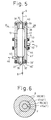
- Figure 5 illustrates a side elevational view of the hot chamber utilized for the present invention.
- Pressurized steam 13 is supplied into the interior of a housing 42, and the steam 13 is then uniformly distributed in heater tubes 41 and 41 ⁇ through a filter 44.
- the heater tubes 41, 41 ⁇ constitute a hot chamber 6 and are provided with cylindrical sleeves 38, 38 ⁇ , respectively, at the upper end of the former and the lower end of the latter, which sleeves are provided with the respective narrow slit 47 (see Fig. 6) of a size which allows the yarn to pass therethrough, and are inserted into the respective heater tubes 41, 41 ⁇ .
- the sleeves, 38, 38 ⁇ are secured in position by the respective flanges 39, 39 ⁇ and fixed to the heater tubes 41, 41 ⁇ , respectively, by screws 40, 40 ⁇ .
- Column-like plugs 36, 36 ⁇ are detachably inserted into the interior of the sleeves 38, 38 ⁇ , respectively, and fixed to the sleeves 38, 38 ⁇ by pins 37, 37 ⁇ , respectively, against the pressure of the pressurized steam 13.
- a discharge pipe 45 is provided for effectively removing a drain 46 generated, especially at an initial stage of the spinning operation, from the hot chamber 6.
- Thetime required for passage of the yarn Y through the hot chamber is preferably within a range of from 0.0005 seconds to 0.15 seconds.
- Figure 6 illustrates a cross-section of the hot chamber 6 taken along the line B-B of Fig. 5.
- the slit 47 is provided in the inner periphery of the sleeve 38 inserted in the interior of the heater tube 41.
- the column-like plug 36 is inserted into the interior of the sleeve 38 so that the outer periphery of the plug 36 engages with the inner periphery of the sleeve 38.
- the interior of the sleeve 38 is completely sealed by the plug 36, except for the slit 47 having a very small cross-section and forming the inlet path 7. Since the cross-section of the slit 47 is made as small as possible, to allow the passage of the yarn Y alone, the substantial fluid seal of the slit 47 is sufficient due to a pressure loss in the slit zone.
- an initial cooling of the yarn in a zone between the spinneret 1 and the surface of the liquid bath contained in the vessel 3 may be carried out in an environmental atmosphere at a room temperature.
- a spinning conduit 50 such as the conventional cooling chimney and/or spinning duct, is preferably provided around the yarn passage between the spinneret 1 and the liquid surface, to protect the yarn from disturbance of the air flow and apply a regular cooling air flow from one side of the yarn passage.
- the spinning conduit 50 may be of the conventional type, comprising for example, a hood made of a metal net, steel plate or perforated sheet or a combination thereof.
- supply of the liquid 2 to the vessel 3 is stopped by operating a three way valve (not shown) disposed upstream of the liquid supply pipe 15, and the liquid 2 remaining in the interior of the vessel 3 is discharged.
- the supply of pressurized air 26 is stopped by closing a valve (not shown) disposed upstream of the first conduit 25, and the supply of the pressurized steam 13 is stopped by operating a three way valve (not shown) disposed upstream of the supply pipe 14 and the steam 13 remaining in the interior of the hot chamber 6 is removed so that the interior of the hot chamber is the atmospheric pressure.
- a yarn suction means such as a suction gun (not shown) is applied to an opening formed by the lowermost sleeve 38 ⁇ provided at the lower end of the hot chamber 6, so that a suction stream is generated along the yarn path through the hot chamber 6.
- the yarn Y spun from the spinneret 1, passed through the opening of the sleeve 19 of the vessel 3 and arrived at the entrance of the opening of the upper sleeve 38 is withdrawn from the interior of the hot chamber 6 through the opening of the upper sleeve 38 of the hot chamber 6, and finally is drawn into the suction gun through the opening of the lower sleeve 38 ⁇ .
- the yarn Y passing through the hot chamber 6 is threaded to the yarn guides 5, 8. Then, after the yarn Y is sequentially engaged in the slits 20, 47, 47 ⁇ of the sleeves 19, 38, 38 ⁇ , the plugs 23, 36 and 36 ⁇ are fitted to the sleeves 19, 38, 38 ⁇ , respectively, and fixed by the pins 24, 37, 37 ⁇ .
- the temperature of the interior of the hot chamber 6 is still at a low level, which tends to generate a large amount of drain in the hot chamber 6.
- the drain may be discharged therefrom by adjusting the opening of a valve (not shown) disposed downstream of the discharging pipe 45.
- the threading operation is carried out while no liquid is in the vessel 3.
- the yarn cannot be sufficiently cooled and adhesion and breakage of the individual filaments is liable to occur.
- the amount of molten polymer discharged from the spinneret may be decreased for a while during the threading operation.
- cooling air may be applied to the as-spun yarn to forcibly cool the same.
- the vessel 3 may be adapted to be capable of displacing downward relative to the spinneret and occupy the lower position only during the threading operation so that the length of a cooling zone becomes larger.
- a small quantity of liquid may be imparted to the yarn just before the yarn enters the slit 20 of the sleeve 19.
- the fiber-forming thermoplastic polymer utilized for the present invention includes polyamide, such as poly- ⁇ -capramide, polyhexamethylene adipamide, polyhexamethylene cebacamide, polytetramethylene adipamide, polyhexamethylene isophthalamide, polydodecamethylene dodecamide, polymetaxylene adipamide, or polyparaxylene adipamide; polyester, such as polyethyleneterephthalate, polymethylene terephthalate, polyethylene 1,2-diphenolethane PP ⁇ -dicarboxylate, or polynaphthaleneterephthalate; polyolefin, such as polyethylene, polypropylene, or polybutene-1; copolymer of polyfluoroethylene-polyfluorovinylidene, polyvinylchloride, polyvinylidenechloride, polyacetal and copolymer and mixed polymer composed of more than two kinds thereof.
- polyamide such as poly- ⁇ -capramide, polyhexamethylene a
- the polymer used for the present invention is polyester.
- the liquid utilized for the present invention may be water, an organic solvent, an inorganic salt, oil or an aqueous solution thereof. Water is most preferable.
- the liquid temperature, liquid depth, and length of the cooling zone between the spinneret and the liquid surface should be selected in accordance with the spinning conditions such as yarn thickness, yarn temperature, take-up speed, and and environmental temperature, so that the yarn is not excessively cooled and drawn in the liquid bath, and the yarn can be solidified by the time the yarn reaches the yarn exit path provided in the bottom of the vessel.
- the variance of the liquid temperature is preferably as small as possible so that the quality difference of the yarn obtained from one spinning unit or the respective spinning units is suppressed.
- An allowable temperature range is preferably ⁇ 10°C, more preferably ⁇ 5°C.
- gauge pressures are all reported as gauge pressures, i.e. above atmospheric pressure, where the gauge pressure is obviously zero.
- the pressure of the steam in the hot chamber is preferably not less than 0.5 kg/cm2 (4.9 x 10⁴ Pa), more preferably in a range of from 1.0 kg/cm2 (9.8 x 10⁴ Pa) to 3.0 kg/cm2 (29 x 104 Pa).
- the length of the hot chamber is preferably in a range of from 5 cm to 100 cm.
- the cross-section of the inlet and outlet paths of the hot chamber along a plane perpendicular to the longitudinal axis of the hot chamber is preferably not more than 4.0 mm2 , more preferably in a range of from 0.01 mm2 to 4.0 mm2.
- the length of each path may preferably be from 1 to 10 cm.
- the steam supplied to the hot chamber is preferably saturated.
- An unsaturated steam may be utilized to minimize the generation of drain midway in a steam supply tube.
- the yarn take-up speed is preferably not less than 2500 m/min so that the yarn quality is further improved.
- the yarn take-up speed is preferably in a range of from 3000 m/min to 6000 m/min.
- sealing of the vessel and the hot chamber is not limited to the illustrated designs but other conventional means can be also adopted as an alternative.
- the dimensions of the slit of the yarn exit provided at the bottom of the liquid vessel were 0.2 mm width, 0.5 mm depth, and 30 mm length. Pressurized air of 0.5 kg/cm2 (4.9 x 10⁴ Pa) was ejected transversely to the slit for removing the liquid concomitant with the yarn so that the liquid content of the yarn was approximately 7% relative to the yarn weight.
- Water was utilized as the liquid bath, the temperature of which was adjusted by a heater provided in the supply tube at various levels. Also, the depth of the liquid bath was changed at various levels.
- Pressurized steam was introduced into the hot chamber through an annular filter having a mesh size of 100 ⁇ m, the pressure of which was changed at various levels.
- the yarn discharged from the liquid bath was heat-treated and drawn in the hot chamber, and after being oiled, taken up at a speed of 4000 m/min as a drawn yarn comprising two filaments having 60 denier (67 dtex) in total.
- Example 2 Another comparative test was conducted in the same manner as Example 1, except for elimination of the liquid bath shown in Fig. 1.
- the distance between the spinneret and the hot chamber was 4900 mm, to compensate for the insufficient cooling of the yarn due to elimination of the liquid bath.
- the characteristics of the resultant yarns obtained by the above respective test runs are listed in Table 1. It will be apparent from the Table that the yarn obtained by run Nos. 1 through 5 according to the present invention are superior, in mechanical properties, to those obtained by run Nos. 6-1 through 6-3 according to the comparative test. That is, the yarn according to the present invention has a greater strength and a smaller elongation as well as a lower shrinkage rate in boiling water. Thus, the yarns obtained from the present invention were applicable for practical use without further treatment.
- a primary modulus is defined by the maximum inclination of a stress-strain curve of the yarn in a zone of elongation of 0% through 2%, while a 5% elongation modulus is defined by the inclination of a straight line connecting a point on the stress-strain curve corresponding to an elongation of 5% and the origin of the curve.
- the resultant yarn was taken up at a speed of 4000 m/min as a drawn yarn comprising two filaments having 60 denier (67 dtex) in total.
- Other conditions were the same as in Example 1.
- the yarn obtained from run No. 10 had a greater strength compared to that from run No. 12, in which the depth of the liquid bath was 80 mm and 180 mm, respectively, for the same reason as given in Example 1. In the case of a 280 mm depth, however, the yarn strength was as same as for a 180 mm depth, which shows that a liquid depth of 180 mm is sufficient for the purpose of the present invention.
- Example 2 The other conditions were the same as in Example 1, and the resultant yarn was taken up at a speed of 4000 m/min as a drawn yarn comprising 34 filaments having 34 denier (38 dtex) in total.
- the depth of the liquid bath is preferably 40 mm.
- Table 3 Run No. Liquid Bath Hot Chamber Yarn Characteristics Temp. (°C) Depth (mm) Steam Pressure (kg/cm2) (kPa) Strength (g/d) (N/tex) Elongation (%) Shrinkage in B.W.
- a spinning test according to the present invention was conducted under conditions similar to those of Example 1, except for varying the discharging rate of polymer spun from the spinneret and the take-up speed of the resultant yarn so that a drawn yarn of 60 d/2 (67 dtex/2 f (the thickness of an individual filament composing the yarn is 30 denier (33 dtex)) was obtained. Also, a comparative test similar to run Nos. 6-2 and 6-3 of Example 1 was conducted.
- a spinning test according to the present invention was conducted under conditions similar to those of Example 1, except for varying the discharging rate of polymer spun from the spinneret so that a drawn yarn of 40 d/2 (44 dtex/2) f (the thickness of an individual filament composing the yarn was 20 denier (22 dtex)) was obtained. Also, a comparative test similar to run Nos. 6-2 and 6-3 of Example 1 was conducted.
- a spinning test according to the present invention was conducted under conditions similar to those of Example 1, except for varying the discharging rate of polymer spun from the spinneret so that a drawn yarn of 20 d/2 (22 dtex/2) f (the thickness of an individual filament composing the yarn was 10 denier (11 dtex)) obtained. Also, a comparative test similar to run Nos. 6-2 and 6-3 of Example 1 was conducted.
Landscapes
- Engineering & Computer Science (AREA)
- Textile Engineering (AREA)
- Mechanical Engineering (AREA)
- Physics & Mathematics (AREA)
- Thermal Sciences (AREA)
- Chemical & Material Sciences (AREA)
- Chemical Kinetics & Catalysis (AREA)
- General Chemical & Material Sciences (AREA)
- Spinning Methods And Devices For Manufacturing Artificial Fibers (AREA)
Description
- The present invention relates to a system for melt-spinning a synthetic yarn from a thermoplastic polymer, more particularly, to a method and an apparatus for obtaining such a yarn having a durable mechanical and thermal stability in practical use, at a low manufacturing cost, by only a single continuous process. This system is suitable for producing for industrial use a yarn composed of thicker individual filaments.
- In the conventional method, a thermoplastic polymer is melted, spun from a spinneret, cooled and solidified, and continuously taken up as a package of an undrawn yarn having a low molecular orientation. Thereafter, the undrawn yarn is drawn while heated, by a separate process, to obtain a drawn yarn having a durable mechanical stability in practical use.
- Recently, to reduce costs and save energy, many attempts have been made to produce a drawn yarn through a single continuous process following the melt-spinning of the polymer from a spinneret.
- A direct spinning system is one such attempt, in which a melt-spinning step is directly connected to a drawing step so that an undrawn yarn spun from a spinneret is continuously introduced, without being taken up as a package, to a group of hot rollers for drawing. This system, however, has a drawback of a high energy consumption because the hot rollers must rotate at a high speed.
- Japanese Examined Patent Publication (Kokoku) No. 35-3104 discloses that a fiber durable for practical use can be obtained by taking up a yarn spun from a spinneret at a high speed. This method, however, requires an expensive, high speed winder, and in addition, it is difficult to maintain a stable operation by avoiding the many filament breakages occurring in the yarn thus produced.
- Japanese Examined Patent Publication (Kokoku) No. 45-1932 proposes a method for producing a drawn yarn, comprising the steps of melt-spinning a thermoplastic polymer, cooling a yarn thus obtained, running the yarn through a hot zone maintained at a temperature above 80°C, and taking up the heat-treated yarn at a speed higher than 4000 m/min. Although a yarn can be produced at a lower cost according to this method, mechanical properties thereof are still inferior to those of the conventional drawn yarn. In addition, a high speed take-up at above 4000 m/min causes similar defects to those of the above prior art.
- A method for obtaining a drawn yarn by running an as-spun yarn through a liquid bath is proposed, for example, in Japanese Examined Patent Publication (Kokoku) No. 35-2721 (corresponding to U.K. Patent No. 803237), Japanese Examined Patent Publication (Kokoku) No. 38-2016 (corresponding to U.K. Patent No. 828986) and Japanese Unexamined Patent Publication (Kokai) No. 58-169513. According to this method, due to a viscous resistance of liquid bath the yarn can be drawn to form a drawn yarn with less elongation. The strength of the yarn, however, is reduced due to a shock exerted thereon when drawn by the resistance of the liquid bath, and further the yarn has an inferior thermal stability, i.e., has a high thermal shrinkage rate in both its dry and wet conditions.
- A method for obtaining a drawn yarn by running an as-spun yarn through a liquid bath and then drawing the yarn during passage through a hot chamber is proposed, for example, in GB-A-908 409, US-A-4 098 864 and US-A-4 009 511.
- An object of the present invention is to provide a system for producing, at a reduced manufacturing cost and under stable conditions, a thermoplastic yarn having an excellent mechanical and thermal stability.
- The present invention, whilst adopting the steps of (a) continuously downwardly extruding a fiber-forming thermoplastic polymer in a molten state from a spinneret to form a filament yarn, (b) passing the as-spun yarn through a liquid cooling bath disposed beneath the spinneret and (c) thence through a hot chamber filled with pressurized steam and provided with a narrow yarn inlet and outlet, the yarn being drawn at least during its passage through the hot chamber, is characterized in that in combination,
- (i) the said step (b) of passing the as-spun yarn through the liquid cooling bath includes passing the yarn vertically through a narrow yarn exit of the liquid cooling bath,
- (ii) after passing through the liquid cooling bath and before entering the hot chamber, the yarn is treated with pressurized air blowing on the yarn, so that at the narrow yarn inlet of the hot chamber the liquid content of the yarn cooled by the step (b) is not more than 20% relative to the yarn weight.
- The feature of using a liquid bath with a restricted yarn exit is not in itself new, and is shown, for example, in US-A-3 221 088, but is new in combination with the other features of the present invention.
- According to the present invention, it is essential to extrude a thermoplastic polymer in a molten state from a spinneret to form a yarn, and to run the yarn along a passage, preferably a substantially rectilinear passage, through a liquid bath disposed beneath the spinneret. To obtain a drawn yarn having good mechanical properties, according to the present inventors' research, it has been found that it is effective to increase stress in the processed yarn against a take-up tension after the as-spun yarn has been cooled and solidified.
- To realize the above favorable conditions, in the conventional method, a running yarn is braked by being wound around a yarn guide after being cooled and solidified by the application of cooling air. This proposal may be effective for the elevation of an internal stress of the yarn, but causes serious defects in that individual filaments composing the yarn are damaged due to abrasion with the yarn guide, resulting in many fluffs in the resultant yarn. This tendency is more significant when the individual filaments are relatively coarse and difficult to sufficiently cool to a low temperature, because the yarn is liable to adhere to the yarn guide under such conditions.
- Contrary to this, according to the present invention, the as-spun yarn is effectively cooled by a liquid bath, in which at the same time an internal stress is increased in the yarn against a drawing force due to the viscosity of the liquid, and thus a uniform drawing can be obtained. In this process, it is important to run the yarn through the liquid bath along a substantially straight passage, whereby a drawn yarn having no thickness unevenness between the respective filaments is obtained.
- According to the present invention, it is important to fluidly seal the yarn exit path of the liquid bath. A yarn running speed at a spinning stage reaches several thousands m/min, and accordingly, much liquid accompanies the yarn withdrawn from the liquid bath, which liquid tends to contaminate the environmental conditions of the process and interferes with the subsequent heat treatment of the yarn. The sealing of the yarn exit path of the liquid bath is intended to minimize the quantity of liquid accompanying the withdrawn yarn.
- It is also essential that the yarn withdrawn from the liquid bath be introduced into a hot chamber filled with pressurized steam having a pressure higher than that of the outer air. According to the present inventors' research, it has been found that, although the yarn may be drawn in the liquid bath due to the resistance caused by a liquid viscosity, the drawn yarn generally has an inferior strength due to violent deformation thereof and in addition is thermally unstable.
- The present inventors have found that the most effective way to improve the yarn qualities is to run the yarn withdrawn from the liquid bath through the hot chamber filled with pressurized steam having a pressure higher than that of the outer air. Inlet and outlet paths for the yarn are provided at opposite ends of the hot chamber, and inhibit the steam from escaping from the chamber. Although the yarn exit path of the liquid bath is effectively sealed as described above, a small amount of liquid escapes through the yarn exit path while adhering to the yarn body. This adhered liquid is often introduced into the hot chamber together with concomitant air. The sealing of the inlet and outlet paths of the hot chamber is intended to minimize the introduction of the concomitant flow into the hot chamber and the leakage of the steam from the interior thereof, so that pressurized steam having a pressure higher than the outer air is always present therein and thus the yarn can be given a uniform heat-treatetment.
- As stated above, it is possible to produce, at a reduced manufacturing cost, a yarn having excellent mechanical properties and thermal stability by only a single continuous process starting from the melt-spinning of a thermoplastic polymer from a spinneret, in which the yarn as spun from the spinneret is passed through a liquid bath disposed beneath the spinneret along a substantially straight passage for cooling, and the cooled yarn is withdrawn from the liquid bath through a fluidly sealed yarn exit path and introduced into a hot chamber filled with pressurized steam and having inlet and outlet paths at opposite ends which paths allow the yarn to pass but inhibit any escape of the steam therethrough, prior to taking up the yarn as a yarn package.
- According to another aspect of the present invention, an apparatus suitable for carrying out the above method of producing a thermoplastic yarn is provided.
- The present invention will be described in more detail with reference to the preferred embodiments illustrated in the following drawings: wherein
- Fig. 1 is a diagramatic side view of a representative embodiment of a process according to the present invention;
- Fig. 2 is a similar view of another embodiment of a process according to the present invention;
- Fig. 3 is a side sectional view of a liquid vessel suitably utilized for the process according to the present invention;
- Fig. 4 is a cross-section taken along the line A-A in Fig. 3;
- Fig. 5 is side sectional view of a hot chamber suitably utilized for the process according to the present invention; and
- Fig. 6 is a cross-section taken along the line B-B in Fig. 5.
- With reference to Fig. 1, a yarn Y melt-spun from a
spinneret 1 is introduced into aliquid bath 2 contained in avessel 3 disposed beneath a spinningconduit 50, such as a conventional cooling chimney and/or a spinning duct, for preliminarily quenching the as-spun yarn prior to introduction to the liquid bath. The yarn thus cooled and solidified is withdrawn from thevessel 3 through ayarn exit path 4 provided in the bottom thereof. Theyarn exit path 4 has a small inner size sufficient to prevent the liquid contained in thevessel 3 from escaping therethrough but allowing the yarn to pass therethrough. The yarn is then rushed into the interior of ahot chamber 6 via ayarn guide 5 for heat-treatment. Thereafter, the heat-treated yarn is withdrawn therefrom via anotheryarn guide 8 and taken up on awinder 12 via a pair of take-up rollers oiling device 9. - The
oiling device 9 may be disposed upstream of thehot chamber 6 and, in turn, thehot chamber 6 may be disposed between the take-up rollers hot chamber 6 can be optionally adjusted by varying the relative speed between therollers - The
hot chamber 6 is provided with inlet andoutlet paths 7 and 7' having a narrow inner size for allowing the yarn to pass therethrough at the opposite ends of thehot chamber 6.Pressurized steam 13 fills the interior of thehot chamber 6 through asupply pipe 14 for heat-treatment of the yarn. Thehot chamber 6 may be of a tubular form having a circular or rectangular cross-section, or another cross-section, provided the pressurized steam can be effectively accommodated therein. In addition, a tape heater (not shown) may be wound around the periphery of thehot chamber 6 to minimize an amount of drain generated at the initial stage of the operation and to reduce the temperature difference between the respective spinning units. Further, preferably thehot chamber 6 is encircled by a thermal insulating member (not shown) to minimize heat radiation therefrom. - A
liquid 2, preferably water, is supplied from aliquid supply pipe 15 to thevessel 3, in which the height of the liquid surface is maintained at a predetermined level while theexcess liquid 17 is discharged from anoverflow tube 16. In this connection, the temperature of the liquid bath is preferably within a range of from 5°C to 90°C, and the time required for passage of the yarn through the liquid bath is preferably within a range of from 0.001 seconds to 0.15 seconds. - The
vessel 3 has a narrowyarn exit path 4 at the bottom thereof to minimize the amount of liquid discharged through theyarn exit path 4 concomitant with the withdrawn yarn. If the sealing of theyarn exit path 4 is insufficient, the liquid concomitant with the yarn becomes excessive, which causes an irregular and/or insufficient heat-treatment of the yarn in thehot chamber 6, as well as a deterioration of the environmental conditions. - Figure 3 illustrates one of the preferred embodiments of the vessel utilized for the present invention, and Fig. 4 is a cross-section taken along to line A-A in Fig. 3. A
tubular housing 18 is secured to the bottom of thevessel 3 by a screw (not shown). Acylindrical sleeve 19 having anarrow slit 20 in the inner surface allowing the yarn to pass therethrough is detachably inserted in thehousing 18, and fixed to thehousing 18 by anotherscrew 22 and aflange 21. A column-like plug 23 is detachably inserted in thesleeve 19 and fixed to theflange 21 by apin 24. According to the above structure, theslit 20 forms a sealedyarn exit path 4. If the width and the length of theslit 20 are selected to be of a small size sufficient to allow the yarn to pass but inhibiting any escape of the liquid therethrough, leakage of the liquid from the vessel can be effectively stopped due to resistance in the slit zone. - To further reduce the leakage of the liquid from the yarn exit path concomitant with the yarn Y,
pressurized air 26 is introduced into afirst conduit 25 and ejected from anaperture 27 at a point midway in theslit 20 in the direction transverse to the yarn exit path. The liquid adhered to the yarn body is thus blown from the yarn and released as amist 31, which is in turn received by abore 28 provided in theplug 23 and opposing theslit 20 and discharged from asecond conduit 30 through anaperture 29. Thus, the liquid concomitant with the yarn Y withdrawn from thevessel 3 is substantially completely removed, whereby the heat-treatment of the yarn in thehot chamber 6 can be effectively carried out without energy loss and the resultant yarn having uniform properties can be obtained under stable operational conditions. In this connection, the liquid content of the yarn at the yarn exit path of the vessel is not more than 20%, preferably not more than 10%, relative to the yarn weight. - The
liquid 2 is fed to thevessel 3 from thesupply pipe 15.Reference numeral 16 designates an overflow pipe inserted into thevessel 3 through an aperture provided in the bottom thereof. Theoverflow pipe 16 is secured to the bottom of thevessel 3 by tightening acap 35 while pressing anO ring 34 disposed between the bottom of thevessel 3 and thecap 35. This causes theO ring 34 to be radially deformed, so that theoverflow pipe 16 can occupy a predetermined position in the height direction and a liquid-tight seal between theover-flow pipe 16 and thevessel 3 can be achieved. An amount ofliquid 17 overflowing from theoverflow pipe 16 is discharged from thevessel 3, and thus the depth of the liquid is maintained at a predetermined level defined by the insertion length of theoverflow pipe 16. The liquid level in thevessel 3 is easily and continuously adjustable by unfastening thecap 35 to remove the pressure applied on theO ring 34, and then varying the insertion length of theoverflow pipe 16. -
Reference numeral 33 designates a funnel-like tray for enhancing the guiding of the yarn Y spun from thespinneret 1 to a tubular portion of thesleeve 19 during the threading step at an initial stage of the spinning operation. Further, thistray 33 also has a function of regulating the liquid flow generated by the passage of the yarn and protecting the yarn from unfavorable vibration. - The
hot chamber 6 is provided with narrow inlet andoutlet paths 7, 7' at the opposite ends thereof sufficiently sealed in a fluid-tight manner to prevent thepressurized steam 13 filled therein from escaping therefrom. If this sealing is insufficient, not only is the energy loss increased due to escape of thepressurized steam 13, but also an air flow concomitant with the yarn is liable to infiltrate the interior of thehot chamber 6 from theinlet path 7, and thus it is difficult to maintain the temperature and the pressure in thehot chamber 6 at a predetermined value. In addition, the escape of thesteam 13 causes an entanglement of individual filaments composing the yarn Y, which results in an unstable yarn take-up and an inferior, uneven yarn quality. - Figure 5 illustrates a side elevational view of the hot chamber utilized for the present invention.
-
Pressurized steam 13 is supplied into the interior of a housing 42, and thesteam 13 is then uniformly distributed inheater tubes 41 and 41ʹ through afilter 44. Theheater tubes 41, 41ʹ constitute ahot chamber 6 and are provided withcylindrical sleeves 38, 38ʹ, respectively, at the upper end of the former and the lower end of the latter, which sleeves are provided with the respective narrow slit 47 (see Fig. 6) of a size which allows the yarn to pass therethrough, and are inserted into therespective heater tubes 41, 41ʹ. The sleeves, 38, 38ʹ are secured in position by therespective flanges 39, 39ʹ and fixed to theheater tubes 41, 41ʹ, respectively, byscrews 40, 40ʹ. Column-like plugs 36, 36ʹ are detachably inserted into the interior of thesleeves 38, 38ʹ, respectively, and fixed to thesleeves 38, 38ʹ bypins 37, 37ʹ, respectively, against the pressure of thepressurized steam 13. - A
discharge pipe 45 is provided for effectively removing adrain 46 generated, especially at an initial stage of the spinning operation, from thehot chamber 6. - Thetime required for passage of the yarn Y through the hot chamber is preferably within a range of from 0.0005 seconds to 0.15 seconds.
- Figure 6 illustrates a cross-section of the
hot chamber 6 taken along the line B-B of Fig. 5. As apparent therefrom, theslit 47 is provided in the inner periphery of thesleeve 38 inserted in the interior of theheater tube 41. The column-like plug 36 is inserted into the interior of thesleeve 38 so that the outer periphery of theplug 36 engages with the inner periphery of thesleeve 38. Thus, the interior of thesleeve 38 is completely sealed by theplug 36, except for theslit 47 having a very small cross-section and forming theinlet path 7. Since the cross-section of theslit 47 is made as small as possible, to allow the passage of the yarn Y alone, the substantial fluid seal of theslit 47 is sufficient due to a pressure loss in the slit zone. - According to the present invention, an initial cooling of the yarn in a zone between the
spinneret 1 and the surface of the liquid bath contained in thevessel 3 may be carried out in an environmental atmosphere at a room temperature. However, a spinningconduit 50, such as the conventional cooling chimney and/or spinning duct, is preferably provided around the yarn passage between thespinneret 1 and the liquid surface, to protect the yarn from disturbance of the air flow and apply a regular cooling air flow from one side of the yarn passage. The spinningconduit 50 may be of the conventional type, comprising for example, a hood made of a metal net, steel plate or perforated sheet or a combination thereof. - Next, the threading operation to the
liquid vessel 3 and thehot chamber 6 will be explained as follows, with reference to Figs. 1, 3 and 5. - First, supply of the liquid 2 to the
vessel 3 is stopped by operating a three way valve (not shown) disposed upstream of theliquid supply pipe 15, and theliquid 2 remaining in the interior of thevessel 3 is discharged. The supply ofpressurized air 26 is stopped by closing a valve (not shown) disposed upstream of thefirst conduit 25, and the supply of thepressurized steam 13 is stopped by operating a three way valve (not shown) disposed upstream of thesupply pipe 14 and thesteam 13 remaining in the interior of thehot chamber 6 is removed so that the interior of the hot chamber is the atmospheric pressure. - Thereafter, the
pins plugs sleeves hot chamber 6, so that a suction stream is generated along the yarn path through thehot chamber 6. According to this suction stream, the yarn Y spun from thespinneret 1, passed through the opening of thesleeve 19 of thevessel 3 and arrived at the entrance of the opening of theupper sleeve 38 is withdrawn from the interior of thehot chamber 6 through the opening of theupper sleeve 38 of thehot chamber 6, and finally is drawn into the suction gun through the opening of the lower sleeve 38ʹ. The yarn Y passing through thehot chamber 6 is threaded to the yarn guides 5, 8. Then, after the yarn Y is sequentially engaged in theslits sleeves plugs sleeves pins pressurized air 26 is supplied to thefirst conduit 25, and theliquid 2 and thepressurized steam 13 are also supplied to thevessel 3 and thehot chamber 6, respectively. The yarn Y is then taken up through therollers winder 12. The threading operation in the system shown in Fig. 2 will be easily understood with reference to the above description of the threading operation in the system shown in Fig. 1. - At an initial stage,the temperature of the interior of the
hot chamber 6 is still at a low level, which tends to generate a large amount of drain in thehot chamber 6. In this case, the drain may be discharged therefrom by adjusting the opening of a valve (not shown) disposed downstream of the dischargingpipe 45. - As stated above, the threading operation is carried out while no liquid is in the
vessel 3. Under these circumstances, the yarn cannot be sufficiently cooled and adhesion and breakage of the individual filaments is liable to occur. To enhance the cooling of the yarn and avoid these problems,the amount of molten polymer discharged from the spinneret may be decreased for a while during the threading operation. Alternatively, cooling air may be applied to the as-spun yarn to forcibly cool the same. Further alternatively, thevessel 3 may be adapted to be capable of displacing downward relative to the spinneret and occupy the lower position only during the threading operation so that the length of a cooling zone becomes larger. To achieve the same purpose, a small quantity of liquid may be imparted to the yarn just before the yarn enters theslit 20 of thesleeve 19. - The fiber-forming thermoplastic polymer utilized for the present invention includes polyamide, such as poly-ε-capramide, polyhexamethylene adipamide, polyhexamethylene cebacamide, polytetramethylene adipamide, polyhexamethylene isophthalamide, polydodecamethylene dodecamide, polymetaxylene adipamide, or polyparaxylene adipamide; polyester, such as polyethyleneterephthalate, polymethylene terephthalate,
polyethylene 1,2-diphenolethane PPʹ-dicarboxylate, or polynaphthaleneterephthalate; polyolefin, such as polyethylene, polypropylene, or polybutene-1; copolymer of polyfluoroethylene-polyfluorovinylidene, polyvinylchloride, polyvinylidenechloride, polyacetal and copolymer and mixed polymer composed of more than two kinds thereof. - Most preferably, the polymer used for the present invention is polyester.
- The liquid utilized for the present invention may be water, an organic solvent, an inorganic salt, oil or an aqueous solution thereof. Water is most preferable.
- The liquid temperature, liquid depth, and length of the cooling zone between the spinneret and the liquid surface should be selected in accordance with the spinning conditions such as yarn thickness, yarn temperature, take-up speed, and and environmental temperature, so that the yarn is not excessively cooled and drawn in the liquid bath, and the yarn can be solidified by the time the yarn reaches the yarn exit path provided in the bottom of the vessel.
- The variance of the liquid temperature is preferably as small as possible so that the quality difference of the yarn obtained from one spinning unit or the respective spinning units is suppressed. An allowable temperature range is preferably ±10°C, more preferably ±5°C.
- In the following description, pressures are all reported as gauge pressures, i.e. above atmospheric pressure, where the gauge pressure is obviously zero.
- The pressure of the steam in the hot chamber is preferably not less than 0.5 kg/cm² (4.9 x 10⁴ Pa), more preferably in a range of from 1.0 kg/cm² (9.8 x 10⁴ Pa) to 3.0 kg/cm² (29 x 10⁴ Pa). The length of the hot chamber is preferably in a range of from 5 cm to 100 cm. The cross-section of the inlet and outlet paths of the hot chamber along a plane perpendicular to the longitudinal axis of the hot chamber is preferably not more than 4.0 mm² , more preferably in a range of from 0.01 mm² to 4.0 mm². The length of each path may preferably be from 1 to 10 cm.
- The steam supplied to the hot chamber is preferably saturated. An unsaturated steam, however, may be utilized to minimize the generation of drain midway in a steam supply tube.
- The yarn take-up speed is preferably not less than 2500 m/min so that the yarn quality is further improved. In view of the operational stability and ease of the threading operation, the yarn take-up speed is preferably in a range of from 3000 m/min to 6000 m/min.
- Note, the sealing of the vessel and the hot chamber is not limited to the illustrated designs but other conventional means can be also adopted as an alternative.
- The effect of the present invention will be more apparent from the following examples:
- A spinning test was carried out by means of an apparatus shown in Fig. 1 with polyethyleneterephthalate chips having an intrinsic viscosity [η] = 0.63. The fixed spinning conditions were as follows:
- Room temperature:
- 15°C
- Spinning temperature:
- 295°C
- Spinneret:
- Dia. of orifice = 0.5 mm,
Number of orifices = 2 - Discharge rate:
- 26.7 g/min
- Distance between spinneret and liquid surface:
- 1400 mm
- Hot chamber:
- Length = 40 cm
Inner dia. = 60 mm
Slit width = 0.2 mm
Slit depth = 0.2 mm
Slit length = 30 mm - The dimensions of the slit of the yarn exit provided at the bottom of the liquid vessel were 0.2 mm width, 0.5 mm depth, and 30 mm length. Pressurized air of 0.5 kg/cm² (4.9 x 10⁴ Pa) was ejected transversely to the slit for removing the liquid concomitant with the yarn so that the liquid content of the yarn was approximately 7% relative to the yarn weight.
- Water was utilized as the liquid bath, the temperature of which was adjusted by a heater provided in the supply tube at various levels. Also, the depth of the liquid bath was changed at various levels.
- Pressurized steam was introduced into the hot chamber through an annular filter having a mesh size of 100 µm, the pressure of which was changed at various levels.
- The yarn discharged from the liquid bath was heat-treated and drawn in the hot chamber, and after being oiled, taken up at a speed of 4000 m/min as a drawn yarn comprising two filaments having 60 denier (67 dtex) in total.
- A comparative test was conducted in the same manner as before, except for elimination of the hot chamber shown in Fig. 1.
- Another comparative test was conducted in the same manner as Example 1, except for elimination of the liquid bath shown in Fig. 1. In this connection, the distance between the spinneret and the hot chamber was 4900 mm, to compensate for the insufficient cooling of the yarn due to elimination of the liquid bath.
- The characteristics of the resultant yarns obtained by the above respective test runs are listed in Table 1. It will be apparent from the Table that the yarn obtained by run Nos. 1 through 5 according to the present invention are superior, in mechanical properties, to those obtained by run Nos. 6-1 through 6-3 according to the comparative test. That is, the yarn according to the present invention has a greater strength and a smaller elongation as well as a lower shrinkage rate in boiling water. Thus, the yarns obtained from the present invention were applicable for practical use without further treatment.
- In a comparison of run No. 1 with run No. 2, it was found that the depth of the liquid bath affects the mechanical properties of the resultant yarn. This is because the cooling efficiency is improved when the depth of the liquid bath is increased from 40 mm to 80 mm.
- Regarding the pressure of the steam supplied to the hot chamber, as shown in run Nos. 2, 3 and 4, the drawability of the yarn is improved as the pressure is elevated, namely, the strength becomes greater and the elongation becomes less. A higher steam pressure such as 3 kg/cm² (29 x 10⁴ Pa), is however, unfavorable, because of a significant drop in the elongation.
- In the Table, a primary modulus is defined by the maximum inclination of a stress-strain curve of the yarn in a zone of elongation of 0% through 2%, while a 5% elongation modulus is defined by the inclination of a straight line connecting a point on the stress-strain curve corresponding to an elongation of 5% and the origin of the curve.

- A spinning test was carried out by means of an apparatus shown in Fig. 1 with polycapramide chips having a viscosity relative to sulfuric acid [ηγ] = 2.6 under conditions of a spinning temperature of 265°C and a room temperature of 15°C. The resultant yarn was taken up at a speed of 4000 m/min as a drawn yarn comprising two filaments having 60 denier (67 dtex) in total. Other conditions were the same as in Example 1.
- A comparative test was conducted in the same manner as before, except for elimination of the hot chamber shown in Fig. 1.
- The characteristics of the resultant yarns obtained by the respective runs are listed in Table 2.
- As apparent from a comparison of run Nos. 7 through 11 according to the present invention, with run No. 12 according to the comparative test, the yarns obtained from the present invention were superior to that from the comparative test, in mechanical properties.
- The yarn obtained from run No. 10 had a greater strength compared to that from run No. 12, in which the depth of the liquid bath was 80 mm and 180 mm, respectively, for the same reason as given in Example 1. In the case of a 280 mm depth, however, the yarn strength was as same as for a 180 mm depth, which shows that a liquid depth of 180 mm is sufficient for the purpose of the present invention.
- For the pressure level of the steam in the hot chamber, results similar to Example 1 were obtained.
Table 2 Run No. Liquid Bath Hot Chamber Yarn Characteristics Temp. (°C) Depth (mm) Steam Pressure (kg/cm²) (kPa) Strength (g/d)(N/tex) Elongation (%) Shrinkage in B.W. (%) 7 15 80 1 (98) 4.2 (0.37) 50 12.2 8 15 80 2 (196) 4.4 (0.39) 51 12.1 9 15 80 3 (294) 3.8 (0.34) 45 10.8 10 15 180 2 (196) 4.7 (0.42) 49 13.1 11 80 280 2 (196) 4.7 (0.42) 41 13.1 12* 15 80 - 2.4 (0.21) 69 6.3 * Comparative test - A spinning test was carried out by means of an apparatus shown in Fig. 1 with polyethyleneterephthalate chips having an intrinsic viscosity [η] = 0.63. The fixed spinning conditions were as follows:
- Room temperature:
- 15°C
- Spinning temperature:
- 295°C
- Spinneret:
- Dia. of orifice = 0.15 mm,
Number of orifices = 34 - Discharging rate of Polymer:
- 15.0 g/min
- The other conditions were the same as in Example 1, and the resultant yarn was taken up at a speed of 4000 m/min as a drawn yarn comprising 34 filaments having 34 denier (38 dtex) in total.
- A comparative test was conducted by means of modifications of the spinning apparatus shown in Fig. 1, in which either or both of the liquid bath and the hot chamber were eliminated.
- The characteristics of the resultant yarns obtained by the respective runs are listed in Table 3.
- As apparent from a comparison of run Nos. 13 through 17 according to the present invention, with run Nos. 18 through 20 according to comparative test, the yarns obtained from the present invention were superior to that from the latter, in mechanical properties.
- It should be noted that, when the depth of the liquid bath was 80 mm, the elongation of the resultant yarn was lower than that of the yarn obtained at a 40 mm depth. Therefore, the depth of the liquid bath is preferably 40 mm.
Table 3 Run No. Liquid Bath Hot Chamber Yarn Characteristics Temp. (°C) Depth (mm) Steam Pressure (kg/cm²) (kPa) Strength (g/d) (N/tex) Elongation (%) Shrinkage in B.W. (%) 13 80 40 1 (98) 4.2 (0.37) 27 8.7 14 80 40 2 (196) 4.4 (0.39) 23 6.5 15 80 40 3 (294) 4.5 (0.40) 23 5.3 16 80 80 1 (98) 4.4 (0.39) 18 9.6 17 15 40 1 (98) 4.6 (0.41) 32 9.9 18* 80 40 - - 3.5 (0.31) 41 64.4 19* - - 1 (98) 4.0 (0.35) 33 9.0 20* - - - - 3.5 (0.31) 82 11.5 * Comparative test - A spinning test according to the present invention was conducted under conditions similar to those of Example 1, except for varying the discharging rate of polymer spun from the spinneret and the take-up speed of the resultant yarn so that a drawn yarn of 60 d/2 (67 dtex/2 f (the thickness of an individual filament composing the yarn is 30 denier (33 dtex)) was obtained. Also, a comparative test similar to run Nos. 6-2 and 6-3 of Example 1 was conducted.
- The characteristics of the resultant yarn obtained from the respective runs are listed in Table 4.

- A spinning test according to the present invention was conducted under conditions similar to those of Example 1, except for varying the discharging rate of polymer spun from the spinneret so that a drawn yarn of 40 d/2 (44 dtex/2) f (the thickness of an individual filament composing the yarn was 20 denier (22 dtex)) was obtained. Also, a comparative test similar to run Nos. 6-2 and 6-3 of Example 1 was conducted.
- The characteristics of the resultant yarn obtained from the respective runs are listed in Table 5.

- A spinning test according to the present invention was conducted under conditions similar to those of Example 1, except for varying the discharging rate of polymer spun from the spinneret so that a drawn yarn of 20 d/2 (22 dtex/2) f (the thickness of an individual filament composing the yarn was 10 denier (11 dtex)) obtained. Also, a comparative test similar to run Nos. 6-2 and 6-3 of Example 1 was conducted.
- The characteristics of the resultant yarn obtained from the respective runs are listed in Table 6.

Claims (26)
- A method for producing a thermoplastic synthetic yarn comprising the steps of (a) continuously downwardly extruding a fiber-forming thermoplastic polymer in a molten state from a spinneret to form a filament yarn (Y), (b) passing the as-spun yarn (Y) through a liquid cooling bath (2) disposed beneath the spinneret (1) and (c) thence through a hot chamber (6) filled with pressurized steam (13)and provided with a narrow yarn inlet (7) and narrow yarn outlet (7a), the yarn being drawn at least during its passage through the hot chamber (6), characterized in that, in combination,(i) the said step (b) of passing the as-spun yarn through the liquid cooling bath (2) includes passing the yarn vertically through a narrow yarn exit (4) of the liquid cooling bath (2),(ii) after passing through the liquid cooling bath (2) and before entering the hot chamber (6), the yarn is treated with pressurized air (26) blowing on the yarn, so that at the narrow yarn inlet (7) of the hot chamber (6) the liquid content of the yarn (Y) cooled by the step (b) is not more than 20% relative to the yarn weight.
- A method for producing a thermoplastic synthetic yarn as defined in claim 1, wherein a drawing of the yarn is started in said liquid bath (2).
- A method for producing a thermoplastic yarn as defined in claim 1 or claim 2, wherein said liquid bath (2) is a water bath.
- A method for producing a thermoplastic yarn as defined in claim 3, wherein the temperature of said water bath (2) is in a range of from 5°C to 90°C.
- A method for producing a thermoplastic yarn as defined in claim 4, wherein the time required for the yarn to pass said water bath (2) is in a range of from 0.001 sec to 0.15 sec.
- A method for producing a thermoplastic yarn as defined in any preceding claim, wherein the water content of said cooled yarn prior to introduction to said hot chamber (6) is not more than 10% relative to the yarn weight.
- A method for producing a thermoplastic yarn as defined in any preceding claim, wherein said pressurized steam (13) in the hot chamber (6) is saturated steam.
- A method for producing a thermoplastic yarn as defined in claim 7, wherein the pressure of said saturated steam is not less than 0.5 kg/cm²G (49 kPa) gauge pressure.
- A method for producing a thermoplastic yarn as defined in claim 8, wherein the pressure of said saturated steam is in a range of from 1.0 kg/cm² to 3.0 kg/cm² (98 to 294 kPa) gauge pressure.
- A method for producing a thermoplastic yarn as defined in any preceding claim, wherein the time required for the yarn to pass said hot chamber (6) is in a range of from 0.0005 sec to 0.15 sec.
- A method for producing a thermoplastic yarn as defined in any preceding claim, wherein the yarn take-up speed at a stage downstream of the hot chamber (6) is in a range of from 2500 m/min to 6000 m/min.
- A method for producing a thermoplastic yarn as defined in claim 11, wherein the yarn take-up speed at a stage downstream of the hot chamber is in a range of from 3000 m/min to 6000 m/min.
- A method for producing a thermoplastic yarn as defined in any preceding claim, wherein the cross-section of said inlet and outlet (7, 7a) of the hot chamber (6) along a plane perpendicular to the longitudinal axis of the hot chamber is not more than 4.0 mm².
- A method for producing a thermoplastic yarn as defined in claim 13, wherein the cross-section of said inlet and outlet (7, 7a) of the hot chamber (6) along a plane perpendicular to the longitudinal axis of the hot chamber is in a range of from 0.02 mm² to 4.0 mm².
- A method for producing a thermoplastic yarn as defined in any preceding claim, wherein the thickness of an individual filament composing said yarn at a stage downstream of the hot chamber is not less than 25 denier (28 dtex).
- A method for producing a thermoplastic yarn as defined in claim 15, wherein the thickness of an individual filament composing said yarn at a stage downstream of the hot chamber is in a range of from 25 denier (28 dtex) to 250 denier (277 dtex).
- An apparatus for producing a thermoplastic yarn from a fiber-forming thermoplastic polymer, comprising:(a) a spinneret (1) for spinning the thermoplastic polymer in a molten state,(b) a spinning conduit (50) disposed adjacent to the lower end of said spinneret,(c) a vessel (3) for receiving a liquid therein, disposed beneath the spinning conduit with an upper surface open to the spinning conduit and provided with a narrow yarn exit path (4) at the bottom thereof, this yarn exit path being provided with an aperture (27) connected to a first conduit (25) for injecting pressurized air (26) transversely to the yarn exit path (4) and another aperture (29) connected to a second conduit (30) for receiving and exhausting the air injected from the first conduit (25) mixed with a mist (31) released from the running yarn,(d) a hot chamber (6) filled with pressurized steam (13), disposed in a passage for a running yarn (Y) discharged from the yarn exit path (4) of the vessel (2) and provided at one end with a narrow inlet path (7) for introduction of the running yarn into the hot chamber (6) and at the other end with a narrow outlet path (7) for discharge of the running yarn from the hot chamber (6), and(e) a means (10, 11, 12) for taking-up the yarn discharged from the hot chamber.
- An apparatus for producing a thermoplastic yarn as defined in claim 17, wherein the cross-section of each of said inlet and outlet paths (7 and 7') of the hot chamber (6) along a plane perpendicular to the longitudinal axis of the paths is not more than 4.0 mm².
- An apparatus for producing a thermoplastic yarn as defined in claim 18, wherein the cross-section of each of said paths (7 and 7') of the hot chamber (6) along a plane perpendicular to the longitudinal axis of the paths is in a range of from 0.02 mm² to 4.0 mm².
- An apparatus for producing a thermoplastic yarn as defined in any of claims 18 to 21, wherein the length of each of said paths (7 and 7a) of the hot chamber (6) along a plane including the longitudinal axis of the paths is in a range of from 1 cm to 10 cm.
- An apparatus for producing a thermoplastic yarn as defined in any of claims 17 to 20, wherein said hot chamber (6) is disposed between a pair of rotating rollers (10, 11) to be brought into contact with the running yarn.
- An apparatus for producing a thermoplastic yarn as defined in any of claims 17 to 21, wherein said vessel (3) is provided with an over-flow pipe (16) for maintaining the liquid surface at a predetermined level.
- An apparatus for producing a thermoplastic yarn as defined in claim 22, wherein the height of an upper open end of said over-flow pipe (16) is adjustable.
- An apparatus for producing a thermoplastic yarn as defined in any of claims 17 to 23, wherein said yarn exit path (4) of the vessel (3) is formed by a longitudinal groove (20) provided in the inner periphery of a tubular sleeve (19), which periphery is tightly engaged with the outer periphery of a plug (23) detachably inserted in the sleeve (19).
- An apparatus for producing a thermoplastic yarn as defined in claim 24, wherein said vessel (3) is provided therein with a funnel-like tray (33) in front of the yarn exit path of the vessel.
- An apparatus for producing a thermoplastic yarn as defined in any of claims 17 to 25, wherein each of said inlet and outlet paths (7, 7') of the hot chamber is formed by a longitudinal groove (47, 47') provided in the inner periphery of a tubular sleeve (38, 38'), which periphery is tightly engaged with the outer periphery of a plug (36, 36') detachably inserted in the sleeve.
Applications Claiming Priority (2)
| Application Number | Priority Date | Filing Date | Title |
|---|---|---|---|
| JP61157039A JPH086203B2 (en) | 1986-07-03 | 1986-07-03 | Method for producing thermoplastic synthetic fiber |
| JP157039/86 | 1986-07-03 |
Publications (3)
| Publication Number | Publication Date |
|---|---|
| EP0251799A2 EP0251799A2 (en) | 1988-01-07 |
| EP0251799A3 EP0251799A3 (en) | 1989-07-19 |
| EP0251799B1 true EP0251799B1 (en) | 1993-06-30 |
Family
ID=15640854
Family Applications (1)
| Application Number | Title | Priority Date | Filing Date |
|---|---|---|---|
| EP87305868A Expired - Lifetime EP0251799B1 (en) | 1986-07-03 | 1987-07-02 | Method and apparatus for producing thermoplastic synthetic yarn |
Country Status (5)
| Country | Link |
|---|---|
| US (1) | US5019316A (en) |
| EP (1) | EP0251799B1 (en) |
| JP (1) | JPH086203B2 (en) |
| KR (1) | KR880001853A (en) |
| DE (1) | DE3786376T2 (en) |
Families Citing this family (31)
| Publication number | Priority date | Publication date | Assignee | Title |
|---|---|---|---|---|
| DE3729062A1 (en) * | 1987-08-31 | 1989-03-09 | Hoechst Ag | METHOD FOR PRODUCING PREPARATION-FREE STRETCHED FIBERS |
| US5578255A (en) * | 1989-10-26 | 1996-11-26 | Mitsubishi Chemical Corporation | Method of making carbon fiber reinforced carbon composites |
| US5149480A (en) * | 1990-05-18 | 1992-09-22 | North Carolina State University | Melt spinning of ultra-oriented crystalline polyester filaments |
| USRE35972E (en) * | 1990-05-18 | 1998-11-24 | North Carolina State University | Ultra-oriented crystalline filaments |
| JPH04182060A (en) * | 1990-11-14 | 1992-06-29 | Nippon Steel Corp | Structure for pouring molten metal in ladle |
| DE4133329C2 (en) * | 1991-10-08 | 1994-09-15 | Hench Automatik App Masch | Process for cooling and granulating strands which melt out of nozzles |
| JP2673625B2 (en) * | 1992-01-23 | 1997-11-05 | 新日本製鐵株式会社 | Nozzle filling structure for molten metal pouring |
| CA2080621A1 (en) * | 1992-03-30 | 1993-10-01 | George M. Kent | Continuous process for spinning and drawing polyamide and apparatus thereof |
| US5362430A (en) * | 1993-07-16 | 1994-11-08 | E. I. Du Pont De Nemours And Company | Aqueous-quench spinning of polyamides |
| DE4336097A1 (en) * | 1993-10-22 | 1995-04-27 | Bayer Ag | Continuous process for melt spinning monofilament threads |
| US5593629A (en) * | 1995-02-22 | 1997-01-14 | Wellman, Inc. | Method for increased productivity of industrial fiber |
| DE19529135A1 (en) * | 1995-08-08 | 1997-02-13 | Brown John Deutsche Eng Gmbh | Method and device for producing polyester yarns |
| US5772942A (en) * | 1995-09-05 | 1998-06-30 | Toyo Boseki Kabushiki Kaisha | Processes for producing polybenzazole fibers |
| DE19546783C1 (en) * | 1995-12-14 | 1997-07-03 | Inventa Ag | Rapid, fully oriented and relaxed filament polyester yarn production |
| DE19546784C2 (en) * | 1995-12-14 | 1999-08-26 | Inventa Ag | Device for the relaxing heat treatment of filament yarns made of synthetic polymers |
| DE19600090A1 (en) * | 1996-01-03 | 1997-07-10 | Bayer Faser Gmbh | Method and device for producing melt-spun monofilaments |
| WO1997036736A1 (en) * | 1996-03-31 | 1997-10-09 | Bernhard Lipp | Process and device for steam-conditioning plastic articles |
| US5733653A (en) * | 1996-05-07 | 1998-03-31 | North Carolina State University | Ultra-oriented crystalline filaments and method of making same |
| CN1197489A (en) * | 1996-07-04 | 1998-10-28 | 巴马格股份公司 | Wet spinning method and device |
| US6160086A (en) * | 1998-07-30 | 2000-12-12 | 3M Innovative Properties Company | Process for removing impurities from polymers |
| TW584680B (en) * | 1999-05-28 | 2004-04-21 | Inventa Fischer Ag | Device for intermingling, relaxing, and/or thermosetting of filament yarn in a melt spinning process, as well as associated processes and the filament yarn manufactured therewith |
| DE10120551A1 (en) * | 2001-04-26 | 2002-10-31 | Barmag Barmer Maschf | Device for melt spinning and winding at least one synthetic thread |
| US20100227984A1 (en) * | 2009-03-05 | 2010-09-09 | Dang Thuy | HYDROLYSIS-RESISTANT POLY (p-PHENYLENEBENZOBISOXAZOLE) (PBO) FIBERS |
| US9080258B2 (en) * | 2009-07-10 | 2015-07-14 | North Carolina State University | Process of making highly oriented and crystalline thermoplastic filaments |
| CN101787578B (en) * | 2009-12-28 | 2011-08-31 | 宁波荣溢化纤科技有限公司 | Preheating tank |
| CN102776587A (en) * | 2011-05-09 | 2012-11-14 | 宜兴市填料厂 | Elastic silk filler molding complete device |
| KR20160137641A (en) * | 2014-04-01 | 2016-11-30 | 코드사 글로벌 엔두스트리옐 이플릭 베 코드 베지 사나위 베 티카레트 아노님 시르케티 | A system for industrial yarn production from composite polyethylene naphthalate material |
| CN109844188B (en) * | 2016-08-03 | 2022-02-11 | 科德沙技术纺织品股份公司 | System and method for monofilament yarn production |
| JP7021328B2 (en) * | 2020-11-10 | 2022-02-16 | コルドサ・テクニク・テクスティル・アノニム・シルケティ | Methods for manufacturing monofilament yarns |
| CN112921422B (en) * | 2021-01-20 | 2022-08-30 | 中国纺织科学研究院有限公司 | Hot box for drawing yarns |
| CN115772711B (en) * | 2022-10-25 | 2023-06-30 | 桐昆集团浙江恒超化纤有限公司 | POY chemical fiber melt spinning equipment and spinning process |
Family Cites Families (34)
| Publication number | Priority date | Publication date | Assignee | Title |
|---|---|---|---|---|
| GB828886A (en) * | 1955-08-29 | 1960-02-24 | Ass Portland Cement | Improvements in and relating to the manufacture of portland cement, lime and the like |
| GB803237A (en) * | 1955-10-26 | 1958-10-22 | Ici Ltd | The production of artificial filaments by melt-spinning |
| US3002804A (en) * | 1958-11-28 | 1961-10-03 | Du Pont | Process of melt spinning and stretching filaments by passing them through liquid drag bath |
| US3084991A (en) * | 1959-07-01 | 1963-04-09 | Union Carbide Corp | Production of an aryl epoxy ether polymer structure |
| NL267905A (en) * | 1960-08-04 | |||
| NL281284A (en) * | 1961-07-24 | |||
| BE635464A (en) * | 1962-07-27 | |||
| NL129960C (en) * | 1963-04-17 | |||
| US3221088A (en) * | 1964-11-02 | 1965-11-30 | Eastman Kodak Co | Process and apparatus for orienting yarn |
| GB1091947A (en) * | 1964-12-18 | 1967-11-22 | Mitsubishi Rayon Co | Method for producing artificial fibers |
| US3291880A (en) * | 1964-12-23 | 1966-12-13 | Du Pont | Process for preparing an undrawn, low birefringence polyamide yarn |
| US3422171A (en) * | 1965-07-07 | 1969-01-14 | Hercules Inc | Process for producing foamed polypropylene monofilament |
| JPS451932Y1 (en) * | 1966-05-20 | 1970-01-27 | ||
| JPS4326326Y1 (en) * | 1966-06-27 | 1968-11-02 | ||
| US3488344A (en) * | 1966-10-07 | 1970-01-06 | Bemberg Spa | Method and apparatus for the production of manmade fibres and manmade fibres obtained thereby |
| US3452132A (en) * | 1966-11-03 | 1969-06-24 | Du Pont | Process of steam drawing and annealing polyester yarn |
| JPS444257Y1 (en) * | 1966-11-25 | 1969-02-17 | ||
| JPS4326331Y1 (en) * | 1968-04-25 | 1968-11-02 | ||
| GB1430449A (en) * | 1973-07-04 | 1976-03-31 | Du Pont | Heavy denier polyamide monofilament and process for the preparation thereof |
| AR204352A1 (en) * | 1974-04-03 | 1975-12-22 | Du Pont | POLYHEXAMETHYLENADIPAMIDE THREAD WITHOUT STRETCHING VAPORIZED AND PROCEDURE FOR OBTAINING IT |
| US3996321A (en) * | 1974-11-26 | 1976-12-07 | E. I. Du Pont De Nemours And Company | Level control of dry-jet wet spinning process |
| US4098864A (en) * | 1976-02-18 | 1978-07-04 | The Firestone Tire & Rubber Company | Steam drawing of polyester monofilament to improve loop strength and resistance to fibrillation |
| US4070431A (en) * | 1976-12-21 | 1978-01-24 | E. I. Du Pont De Nemours And Company | Improved yarn extraction process |
| EP0030648B1 (en) * | 1979-11-30 | 1984-03-07 | Sekisui Jushi Kabushiki Kaisha | Method for the production of polyethylene terephthalate packing material |
| ZA81653B (en) * | 1980-02-18 | 1982-03-31 | Ici Ltd | Process for forming a continous filament yarn from a melt spinnable synthetic polymer and novel polyester yarns produced by the process |
| EP0034880B1 (en) * | 1980-02-18 | 1986-03-05 | Imperial Chemical Industries Plc | Process for forming a continuous filament yarn from a melt spinnable polyethylene terephthalat and novel polyester yarns produced by the process |
| JPS5816913A (en) * | 1981-07-17 | 1983-01-31 | Nippon Denso Co Ltd | Controller for air conditioner of automobile |
| US4425293A (en) * | 1982-03-18 | 1984-01-10 | E. I. Du Pont De Nemours And Company | Preparation of amorphous ultra-high-speed-spun polyethylene terephthalate yarn for texturing |
| JPS60134011A (en) * | 1983-12-22 | 1985-07-17 | Toray Ind Inc | Method and apparatus for melt-spinning of thermoplastic polymer |
| JPH0639726B2 (en) * | 1984-07-13 | 1994-05-25 | 東レ株式会社 | Synthetic fiber melt spinning equipment |
| US4702871A (en) * | 1985-06-20 | 1987-10-27 | Toray Industries, Inc. | Method for melt-spinning thermoplastic polymer fibers |
| JP3135632B2 (en) * | 1990-09-27 | 2001-02-19 | 株式会社東芝 | Magnetic head |
| JPH053104A (en) * | 1991-06-26 | 1993-01-08 | Murata Mfg Co Ltd | Through type varistor |
| JPH082016A (en) * | 1994-06-20 | 1996-01-09 | Canon Inc | Printer |
-
1986
- 1986-07-03 JP JP61157039A patent/JPH086203B2/en not_active Expired - Lifetime
-
1987
- 1987-07-02 DE DE87305868T patent/DE3786376T2/en not_active Expired - Fee Related
- 1987-07-02 KR KR1019870007016A patent/KR880001853A/en not_active Application Discontinuation
- 1987-07-02 EP EP87305868A patent/EP0251799B1/en not_active Expired - Lifetime
-
1989
- 1989-07-24 US US07/383,434 patent/US5019316A/en not_active Expired - Fee Related
Also Published As
| Publication number | Publication date |
|---|---|
| KR880001853A (en) | 1988-04-27 |
| DE3786376T2 (en) | 1993-10-14 |
| EP0251799A3 (en) | 1989-07-19 |
| JPS6312710A (en) | 1988-01-20 |
| EP0251799A2 (en) | 1988-01-07 |
| US5019316A (en) | 1991-05-28 |
| JPH086203B2 (en) | 1996-01-24 |
| DE3786376D1 (en) | 1993-08-05 |
Similar Documents
| Publication | Publication Date | Title |
|---|---|---|
| EP0251799B1 (en) | Method and apparatus for producing thermoplastic synthetic yarn | |
| EP0147173B2 (en) | Method and apparatus for melt-spinning thermoplastic polymer fibers | |
| US5558825A (en) | Method and apparatus for producing polyester fiber | |
| EP1863958B1 (en) | Process for producing polyphenylene sulfide filament yarns | |
| EP0934434B1 (en) | Process for making high tenacity aramid fibers | |
| US6036895A (en) | Process and device for the formation of monofilaments produced by melt-spinning | |
| US4702871A (en) | Method for melt-spinning thermoplastic polymer fibers | |
| US6090485A (en) | Continuous filament yarns | |
| WO1998018984A9 (en) | Process for making high tenacity aramid fibers | |
| US4780073A (en) | Apparatus for melt-spinning thermoplastic polymer fibers | |
| EP0370816B1 (en) | Process for preparing polyester filamentary material | |
| US4238439A (en) | Process for producing self-crimping polyamide yarns | |
| US6420025B1 (en) | Method for producing ultra-fine synthetic yarns | |
| US5853640A (en) | Process for making high tenacity aramid fibers | |
| JPH03137209A (en) | Spinning and cooling of synthetic fiber and apparatus therefor | |
| EP3455395B1 (en) | Apparatus and method for monofilament yarn production | |
| US6270532B1 (en) | Element for washing or treating a yarn or similar structure with a fluid | |
| JP2000314031A (en) | Production of high-strength polyester fiber | |
| KR910009692B1 (en) | Melt spinning method of polyamide fiber | |
| JPS63256707A (en) | Apparatus for melt spinning thermoplastic polymer | |
| KR950000726B1 (en) | Process for preparing a polyester fiber | |
| JP3227835B2 (en) | Refueling guide and metering refueling device using the same | |
| JPS62223314A (en) | Method for melt spinning of thermoplastic synthetic yarn | |
| KR920010258B1 (en) | Producing process of good dyeing property | |
| JPH0881822A (en) | Production of polyamide fiber by multifilament multi-yarn manufacturing process |
Legal Events
| Date | Code | Title | Description |
|---|---|---|---|
| PUAI | Public reference made under article 153(3) epc to a published international application that has entered the european phase |
Free format text: ORIGINAL CODE: 0009012 |
|
| AK | Designated contracting states |
Kind code of ref document: A2 Designated state(s): DE FR GB IT |
|
| PUAL | Search report despatched |
Free format text: ORIGINAL CODE: 0009013 |
|
| AK | Designated contracting states |
Kind code of ref document: A3 Designated state(s): DE FR GB IT |
|
| 17P | Request for examination filed |
Effective date: 19900108 |
|
| 17Q | First examination report despatched |
Effective date: 19910830 |
|
| GRAA | (expected) grant |
Free format text: ORIGINAL CODE: 0009210 |
|
| AK | Designated contracting states |
Kind code of ref document: B1 Designated state(s): DE FR GB IT |
|
| ITF | It: translation for a ep patent filed | ||
| REF | Corresponds to: |
Ref document number: 3786376 Country of ref document: DE Date of ref document: 19930805 |
|
| ET | Fr: translation filed | ||
| PLBE | No opposition filed within time limit |
Free format text: ORIGINAL CODE: 0009261 |
|
| STAA | Information on the status of an ep patent application or granted ep patent |
Free format text: STATUS: NO OPPOSITION FILED WITHIN TIME LIMIT |
|
| 26N | No opposition filed | ||
| PGFP | Annual fee paid to national office [announced via postgrant information from national office to epo] |
Ref country code: GB Payment date: 19940622 Year of fee payment: 8 |
|
| PGFP | Annual fee paid to national office [announced via postgrant information from national office to epo] |
Ref country code: DE Payment date: 19940708 Year of fee payment: 8 |
|
| PGFP | Annual fee paid to national office [announced via postgrant information from national office to epo] |
Ref country code: FR Payment date: 19940711 Year of fee payment: 8 |
|
| PG25 | Lapsed in a contracting state [announced via postgrant information from national office to epo] |
Ref country code: GB Effective date: 19950702 |
|
| GBPC | Gb: european patent ceased through non-payment of renewal fee |
Effective date: 19950702 |
|
| PG25 | Lapsed in a contracting state [announced via postgrant information from national office to epo] |
Ref country code: DE Effective date: 19960402 |
|
| PG25 | Lapsed in a contracting state [announced via postgrant information from national office to epo] |
Ref country code: FR Effective date: 19960430 |
|
| REG | Reference to a national code |
Ref country code: FR Ref legal event code: ST |
|
| REG | Reference to a national code |
Ref country code: FR Ref legal event code: ST |
|
| REG | Reference to a national code |
Ref country code: FR Ref legal event code: ST |
|
| PG25 | Lapsed in a contracting state [announced via postgrant information from national office to epo] |
Ref country code: IT Free format text: LAPSE BECAUSE OF NON-PAYMENT OF DUE FEES;WARNING: LAPSES OF ITALIAN PATENTS WITH EFFECTIVE DATE BEFORE 2007 MAY HAVE OCCURRED AT ANY TIME BEFORE 2007. THE CORRECT EFFECTIVE DATE MAY BE DIFFERENT FROM THE ONE RECORDED. Effective date: 20050702 |