EP0251101A2 - Urine pipe wiping apparatus for livestock building - Google Patents
Urine pipe wiping apparatus for livestock building Download PDFInfo
- Publication number
- EP0251101A2 EP0251101A2 EP87108905A EP87108905A EP0251101A2 EP 0251101 A2 EP0251101 A2 EP 0251101A2 EP 87108905 A EP87108905 A EP 87108905A EP 87108905 A EP87108905 A EP 87108905A EP 0251101 A2 EP0251101 A2 EP 0251101A2
- Authority
- EP
- European Patent Office
- Prior art keywords
- center shaft
- urine pipe
- pipe
- urine
- wiper
- Prior art date
- Legal status (The legal status is an assumption and is not a legal conclusion. Google has not performed a legal analysis and makes no representation as to the accuracy of the status listed.)
- Granted
Links
Images


Classifications
-
- A—HUMAN NECESSITIES
- A01—AGRICULTURE; FORESTRY; ANIMAL HUSBANDRY; HUNTING; TRAPPING; FISHING
- A01K—ANIMAL HUSBANDRY; CARE OF BIRDS, FISHES, INSECTS; FISHING; REARING OR BREEDING ANIMALS, NOT OTHERWISE PROVIDED FOR; NEW BREEDS OF ANIMALS
- A01K1/00—Housing animals; Equipment therefor
- A01K1/01—Removal of dung or urine, e.g. from stables
- A01K1/0103—Removal of dung or urine, e.g. from stables of liquid manure
Definitions
- This invention relates to a urine pipe wiping apparatus for a livestock building for pushing such a mixture liquid comprising mainly urine and partially droppings that is flown into a urine pipe provided on a bottom of a waste pit provided below a row of livestock crates in a livestock building in order to discharge the same forcibly to the outside of the building.
- FIG. 14 A construction of the interior of a livestock building such as a swine building for hogs, nursery pigs, farrowing pigs or the like or a cattle building for cows, cattles or the like is shown in Fig. 14, for instance.
- This is typically adaptable for a swine building. Namely, this is so constructed that there are installed on the floor surface of a livestock building at least one row of a large number of swine crates A, A, Vietnamese disposed one adjacent one with another, each being surrounded by fences a, a, Vietnamese, and along the row of crates there is provided a working sideway B, and a long waste gutter or pit C common to all the swine crates A, A, ).
- a row of grill or grid members D, D, Vietnamese are provided so as to cover the top surfaces of pit portions of the respective swine crates, and the bottom surface of the long pit C is so formed that both side surfaces of the center line thereof are formed into slant surfaces which are gradually lowered toward the center line, and a long urine pipe E of which an upper surface is made into a slit opening e is provided along on the center line and is embedded therein in such a slightly inclined condition and a lower end portion thereof is situated over a discharging passage not shown.
- wastes comprising droppings and urine from the respective swine crates are dropped on the bottom surface of the pit C through the respective grids D, D, Vietnamese, and the droppings are accumulated on both side slant surfaces of the bottom, and the urine is flown into the urine pipe E through the upper slit e thereof, and the urine contained in the urine pipe E is automatically flown due to its inclination to be discharged to the outside through the discharging passage.
- the accumulated droppings are scraped off outside by a scraper at a proper time.
- the urine pipe E is about 10cm in diameter, and several ten meters long, and it is of course that it is long according to the length of the row of the livestock crates to be provided.
- the gist of this invention is that the top part of a urine pipe is arranged to be opened and closed as desired and in a closed condition thereof a mixture liquid contained in the urine pipe is swept by a wiper for pushing a whole sectional area of the interior of the urine pipe and in a opened condition thereof flowing of the mixture liquid into the urine pipe is permitted, and, on the other hand, the wiper is constructed into such a piston valve type one that at the time of its running forwards in the direction sweeping a mixture liquid the same pushes the liquid so as to cover the whole sectional area of the closed pipe to result in a good removal of the mixture liquid, and at the time of its running rearwards in the reverse direction the same does not push back the mixture liquid to result in a smooth and rapid returning.
- a purpose of this invention is to provide a urine pipe wiping apparatus free from the foregoing conventional defects and making it possible to remove a mixture liquid of wastes from the interior of a urine pipe smoothly and with a good and high efficiency, and, according to this invention, it is characterized in that it comprises a combination of a urine pipe and a wiper which is slidably movable forwrds and rearwards along on the inner surface of the urine pipe in its longitudinal direction, and the urine pipe is so constructed that a part of a pipe body wall thereof is formed into a mounting member panel which is provided with a large number of perforation holes disposed in its longitudinal direction so as to leave predetermined equal intervals therebetween and is additionally provided with a longitudinal slit made through the whole length of the interior thereof in its longitudinal direction so that a slide panel provided with a large number of openings disposed in its longitudinal direction as to leave the same intervals therebetween as those left between the foregoing large number of holes may be slidably inserted into the slit of the
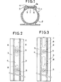
- Fig. 1 is a sectional view of one example of a urine pipe of this invention
- Fig. 2 is a top plan view of the urine pipe, partly omitted, in its opened condition
- Fig. 3 is a top plan view of the urine pipe, partly omitted, in its closed condition
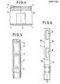
- Fig. 4 is a side view of part of the urine pipe
- Fig. 5 is a top plan view of a mounting member panel, partly omitted
- Fig. 6 is a top plan view of a slide panel, partly omitted
- Fig. 7 is a sectional side view of a wiper of the apparatus
- Fig. 8 is a sectional view taken along the line VIII - VIII in Fig. 7, Fig.
- FIG. 9 is a sectional view taken along the line IX - IX in Fig. 7
- Fig. 10 is a sectional view of one embodying example of this invention apparatus
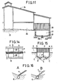
- Fig. 11 is a side view, partly omitted, of a swine building provided with this invention apparatus
- Fig. 12 is a sectional side view of one end section thereof
- Fig. 13 is a sectional side view of the other end section thereof
- Fig. 14 is a top plan view of part of a conventional construction of a conventional swine building
- Fig. 15 is a sectional view taken along the line XV - XV in Fig. 14, and
- Fig. 16A and Fig. 16B are sectional perspective views of urine pipe thereof.
- Figs. 1 - 10 show one embodying example of this invention urine pipe wiping apparatus.
- numeral 1 denotes a urine pipe.
- the urine pipe 1 is composed plural circular pipe members which are jointed together in a single pipe 1 in such a manner that adjacent ones thereof are connected together by applying a joint member .2 to the outer peripheral surfaces of abutted parts thereof and by interposing an adhesive agent between the joint member 2 and the abutted parts thereof, to have a predetermined length thereof in compliance: with a predetermined length of a swine building, for instance.
- a top portion of the pipe body of the urine pipe 1 is provided with a top opening 3a extending throughout the whole length of the pipe 1, and guide frames 3, 3 are formed on both sides of the opening 3a, and a mounting member panel 4 having a proper thickness so formed as described below is mounted or inserted in the guide groove frames 3, 3.
- the mounting member panel 4 is made to have the same length as the urine pipe 1, and the full length thereof may be composed of a single panel or plural panel members of a proper length connected together into a single panel.
- the mounting member panel 4 as clearly shown in Fig. 5,. is provided with a large number of vertically perforated holes 5, 5, .
- each of the perforation holes 5 is formed into such a funnel-shape one that the diameter thereof is gradually increased towards the lower end surface thereof, and thereby there can be obtained such a preferable result that inflowing of a mixture of wastes comprising mainly urine and partially the droppings therethrough into the urine pipe 1 is facilitated.
- a slide panel 7 prepared separately from the pipe constituent members mentioned above is inserted into the slit 6 of the foregoing mounting member panel 4 of the pipe body.
- the slide panel 7 is made so that the length thereof may become somewhat longer than that of the pipe body, and at least one of the protruded external end parts 7a and 7a is to be connected to a reciprocating driving source situated outside.
- the slid plate 7 provided with a large number of openings 8, 8, Vietnamese, preferably, long openings as illustrated, made therethrough and in the longitudinal direction thereof so as to leave predetermined equal intervals therebetween.
- the number of the openings 8, 8, Vietnamese are the same as that of the perforation holes 5, 5, Vietnamese and each interval between the centers of the adjacent openings 5, 5 is the same as each interval between those of the adjacent holes 8, 8.
- the slide panel 7 is composed of a member, but it may be composed of plural ones welded together, for instance.
- the slide panel 7 is slidably movable along the mounting member panel 4, so that the urine pipe 1 of this invention is so operated that there may be brought about an open condition in which all the holes 8, 8, Vietnamese of the slide panel 7 and all the through openings 5, 5, Vietnamese of the mounting member panel 4 are in alignment with each other as shown in Fig. 2 and a closed condition in which those holes 8, 8, Vietnamese are those through openings 5 , 5 , Vietnamese are in nonalignment with each other as shown in Fig. 3.
- Both side edges of the slide panel 7 may be straight line ones, but it is preferable to form them into uneven ones having recessed side edge parts7b and 7b, so that the resistance to sliding of the slide panel 7 along the mounting member panel 4 can be decreased.
- the urine pipe 1 is made of any kind of material having an anticorrosion property such as of stainless steel, hard synthetic resin such as polyvinyl chrolide or the like, and, for instance, the inner diameter thereof is 100 mm, the length thereof is 100 m, and distance between the centers of the adjacent holes 5, 5, made in the mounting member panel 4 is set to be 150 mm.
- the slide panel 7 is made of similar material such as stainless steel, polyvinyl chrolide or the like, and the width thereof is 50 mm, the thickness thereof is 1.5 mm and the length thereof is 101 m.
- a urine pipe wiping apparatus is constructed by assembling the urine pipe 1 constructed as above, with a wiper 9 having the following construction in such a manner that the wiper 9 is slidably mounted as shown in Fig. 10, in order to be used for removing the mixture liquid in the urine pipe 1 installed in the livestock building.
- the wiper 9 is composed of a center shaft 10 of which both end portions have connecting holes 10a and 10a for being tied with strings such as cables, wires, ropes or the like, an annular member 11 which is positioned concentrically with the center shaft 10 to surround the same and is arranged to be slidable along the inner peripheral surface of the urine pipe 1, a front frame body 12 which supports the front surface of the annular member 11, and is slidable along on the center shaft 10 and permits a liquid to flow therethrough, a rear frame body 13 which supports the rear surface of the annular member 11, and is slidable along on the center shaft 10 and permits a liquid to flow therethrough, and a valve plate 15 fixed to the center shaft 10 within a space 14 formed between the annular member 11 and the rear frame body 13 so that the plate 15 may be moved forwards and rearwards in conjunction with reciprocal movement of the center shaft 10 to close and open an inside hollow opening 16 of the annular member 11.
- the annular member 11 is composed of a circular annular gasket lla made of any material having a good close contact property with the inner peripheral surface of the circular urine pipe 1 and a durability or toughness and a circular annular clamping member 11b which is made of any anticorrosion material such as stainless steel, hard synthetic resin or the like and is formed into a U-shaped one, for instance, for holding firmly the annular gasket 11a by clamping from both sides thereof by means of clamping, or by an adhesive agent or the like.
- the front frame body 12 is composed of at least two arm bars 18, four arm bars in the illustrated example, which are disposed circularly about the center shaft 10 so as to leave such each space 17 between mutually adjacent ones that allow a liquid to flow therethrough, and the rearward ends of the arm bars 18 are fixed to the front surface of the annular member 11, and the forward ends thereof are connected to a slidable tube 19 slidably mounted on the center shaft 10.
- the rear frame body 13 is composed of at least two arm bars 21, four arm bars in the illustrated example, which are disposed circularly about the center shaft 10 so as to leave such each space 20 between mutually adjacent ones that allow a liquid to flow therethrough, and so as to extend from the rear surface of the annular member 11 rearwards, and a back plate 23 which are connected at its outer periphery to the rearward ends of these rear arm bars 21 and is alidably mounted on the center shaft 10 through a slidable tube 22 provided on its inner periphery.
- the valve plate 15 is in the form of a circular disk which is larger in diameter than the inside hollow opening 16 of the annular member 11 so that the same may be brought into its close contact with the rear surface of the annular member 11 in the course of its forward movement as shown by chain lines in Fig. 7 and in its rearward movement the same may be brought into contact with the front surface of the back plate 23 for being prevented from its further rearward movement and thus the same may be given an reciprocating or piston movement.
- the clamping member 11b of the annular member 11, the front arm bars 18, the rear arm bars 21, the valve plate 15, and the back plate 23 are made of any corrosion resisting material such as a stainless steel, hard synthetic resin. In the illustrated examples, they are all made of metallic material and respective abutted portions thereof are jointed together by welding.
- the front arm bars 18 and the slidable tube 19 and the rear arm bars 21 and the slidable tube 22 are adhered together with an adhesive agent.
- the slidable tube 19 and 22 are made of any durable anti- frictional material such as rubber, synthetic resin or the like.
- the urine pipe 1 and the wiper 9 thus constructed are assembled together as shown in Fig. 10 into a urine pipe wiping apparatus of this invention, which is adaptable for a livestock building.
- F igs.11 - 13 show one example where the above apparatus is adapted to a swine building.
- numeral 24 denotes a swine building, and there is provided at the center line of the floor of the same a working sideway 25, and on both sides of the sideway 25 there are provided two rows of swine crates 26, 26, Vietnamese, each row thereof being disposed in a line in the longitudinal direction, namely, in the direction perpendicularly to the surface of the drawing sheet.
- Numeral 27 denotes a gutter or pit common to each row of swine crates 26, 26, ., numeral 28, 28, .
- numeral 29 denotes a bottom of the pit 27 for wastes.
- the bottom 29 is formed into slant surfaces 29a and 29a declined gradually towards the center line thereof, and at the resultant lowest center line portion thereof there is installed the foregoing urine pipe 1 of this invention in such a manner that the same may be slightly inclined from one end thereof towards the other end thereof, and the wiper 9 of this invention is inserted into the urine pipe 1 in such a manner that the outer periphery of the annular member 11 thereof may be slidably along on the inner peripheral surface of the urine pipe 1, and ropes 30, 30 are attached, at their one ends, to the connecting holes 10a and lOa made in both the end portions of the center shaft 10, and the other ends of the ropes 30, 30 are connected to a driving apparatus having a reversible motor.
- Both end portions of the slide panel 7 slidably inserted in the horizontal slit 6 of the mounting member panel 4 which constitutes the top portion of the urine pipe 1 are protruded outwards from both ends of the urine pipe 1, and the resultant external end portions 7a and 7a thereof are connected through chains or sprockets 32, 32 to the reciprocating pulling means 33, 33.
- a discharging outlet 34 made through the lower end portion of the urine pipe 1 is situated to be open to the upper open surface of a discharging channel 35 situated therebelow and at its right angle therewith.
- a scraper denoted by numeral 36 is for scraping accumulated droppings on both the slant side surfaces 29a and 29a of the bottom 29 of the pit 27, and is connected to both ends of the ropes 30, 30 applied to drums 37, 37 provided on both terminal end sides of.the foregoing pulling means 33, 33 so as to be rec ip ro - c a tabl e right and left by the respective pulling operations of the pulling means 33, 33.
- the respective pulling means 33, 33 are provided with engaging arms 33a and 33a which are to be brought into engagement with engaging balls 38, 38 and be inclined by being brought into engagement with engaging balls 38, 38 fixed to respective predetermined portions of the reciprocating ropes 30 so that the slide panel 7 may be moved forwards and rearwards by a predetermined distance by the respective inclinations of the engaging arms 33a and 33a and consequently the closing and opening of all the holes 5, 5, Vietnamese of the urine pipe 1 can be carried out.
- Numeral 39, 39 denote limit switches for the motor 31.
Abstract
Description
- This invention relates to a urine pipe wiping apparatus for a livestock building for pushing such a mixture liquid comprising mainly urine and partially droppings that is flown into a urine pipe provided on a bottom of a waste pit provided below a row of livestock crates in a livestock building in order to discharge the same forcibly to the outside of the building.
- A construction of the interior of a livestock building such as a swine building for hogs, nursery pigs, farrowing pigs or the like or a cattle building for cows, cattles or the like is shown in Fig. 14, for instance. This is typically adaptable for a swine building. Namely, this is so constructed that there are installed on the floor surface of a livestock building at least one row of a large number of swine crates A, A, ..... disposed one adjacent one with another, each being surrounded by fences a, a, ....., and along the row of crates there is provided a working sideway B, and a long waste gutter or pit C common to all the swine crates A, A, ..... is made in the floor so as to extend throughout the whole length of the row of swine crates and cross respective parts of the floors of the crates as shown in Fig. 15, and a row of grill or grid members D, D, ..... are provided so as to cover the top surfaces of pit portions of the respective swine crates, and the bottom surface of the long pit C is so formed that both side surfaces of the center line thereof are formed into slant surfaces which are gradually lowered toward the center line, and a long urine pipe E of which an upper surface is made into a slit opening e is provided along on the center line and is embedded therein in such a slightly inclined condition and a lower end portion thereof is situated over a discharging passage not shown. Accordingly, wastes comprising droppings and urine from the respective swine crates are dropped on the bottom surface of the pit C through the respective grids D, D, ....., and the droppings are accumulated on both side slant surfaces of the bottom, and the urine is flown into the urine pipe E through the upper slit e thereof, and the urine contained in the urine pipe E is automatically flown due to its inclination to be discharged to the outside through the discharging passage. The accumulated droppings are scraped off outside by a scraper at a proper time. In general, the urine pipe E is about 10cm in diameter, and several ten meters long, and it is of course that it is long according to the length of the row of the livestock crates to be provided.
- Thus, in the case of the removal treatment of the wastes of this kind, it is desirable from the point of view of the subsequent utilization of them that the droppings and urine thereof are separated from each other as much as possible and only the urine is discharged from the urine pipe, but it is actually in a general practice that some of the droppings is joined in the urine, so that a mixture liquid thereof is resulted and is flown into the urine pipe. Consequently, this mixture liquid is poor in fluidity, and there is resulted a difficulty in being automatically or spontaneously discharged. Hitherto, it has been carried out that the installed inclination degree of the urine pipe is made larger in order to accelerate the discharge of the mixture liquid, but it is inconvenient in that not only costs for the foundation or grounding work for the building become vast, but also the discharging efficiency cannot be obtained remarkably. In addition, it is not avoidable that the discharge of the mixture liquid is not sufficient and consequently putrefied odor thereof is strong and there is formed an unsanitary environmental atmosphere, which becomes the cause of disease of the livestock such as swine or the like. In order to forcibly discharge the mixture liquid thereof flown into the urine pipe, it is in principally that the mixture liquid has to be pushed to be flown out by any mechanical means, but in this case, it is unavoidable that a comparatively large amount of the mixture liquid is flooded sideways outside the urine pipe through the top slit thereof at the time of the sweeping operation by the mechanical means, and as a result thereof a flown amount thereof in the longitudinal direction of the urine pipe is very small and thus the discharging or removing efficiency is very low.
- Hitherto, there has been used, instead of the urine pipe having the long slit e at the top part thereof in the longitudinal direction, as shown in Fig. 16A, such a type of urine pipe that, as shown in Fig. 16B, the top wall of the pipe body thereof is provided with a large number of spaced openings f, f, ..... so made therethrough as to be disposed in the longitudinal direction.
- With the urine pipe of this type, an amount of the droppings which are mixed in the urine becomes smaller than the foregoing slit type urine pipe E, but it is still unavoidable that some of the droppings and the urine are mixed to result in a mixture liquid, which is flown into the urine pipe, so that the mixture liquid is very bad in fluidity and the spontaneous discharge thereof is difficult. In this case also, any compulsory discharge operation has to be carried out, but it is unavoidable to overflow the mixture liquid through the large number of the openings f, f,..... outside the urine pipe, and thus a good efficient discharging or removing operation cannot be performed.
- The inventor of this application, in view of the urine pipe sweeping problems as explained above, and as a result of various researches and studies, the following invention has been made.
- Namely, the gist of this invention is that the top part of a urine pipe is arranged to be opened and closed as desired and in a closed condition thereof a mixture liquid contained in the urine pipe is swept by a wiper for pushing a whole sectional area of the interior of the urine pipe and in a opened condition thereof flowing of the mixture liquid into the urine pipe is permitted, and, on the other hand, the wiper is constructed into such a piston valve type one that at the time of its running forwards in the direction sweeping a mixture liquid the same pushes the liquid so as to cover the whole sectional area of the closed pipe to result in a good removal of the mixture liquid, and at the time of its running rearwards in the reverse direction the same does not push back the mixture liquid to result in a smooth and rapid returning.
- Namely, a purpose of this invention is to provide a urine pipe wiping apparatus free from the foregoing conventional defects and making it possible to remove a mixture liquid of wastes from the interior of a urine pipe smoothly and with a good and high efficiency, and, according to this invention, it is characterized in that it comprises a combination of a urine pipe and a wiper which is slidably movable forwrds and rearwards along on the inner surface of the urine pipe in its longitudinal direction, and the urine pipe is so constructed that a part of a pipe body wall thereof is formed into a mounting member panel which is provided with a large number of perforation holes disposed in its longitudinal direction so as to leave predetermined equal intervals therebetween and is additionally provided with a longitudinal slit made through the whole length of the interior thereof in its longitudinal direction so that a slide panel provided with a large number of openings disposed in its longitudinal direction as to leave the same intervals therebetween as those left between the foregoing large number of holes may be slidably inserted into the slit of the mounting.member panel and thereby those holes of the mounting member panel may be closed and opened by the slidable movement of the slide panel, and the wiper comprises a center shaft which is movable forwards and rearwards in the longitudinal direction of the foregoing pipe, an annular member which is positioned so as to surround the center shaft so that there may be defined inside the same a liquid passing hollow opening about the center shaft, a front frame body which supports a front surface of the annular member and is slidably movable along on the center shaft and allows a liquid to pass therethrough, a rear frame body which supports a rear surface of the annular member and is slidably movable along on the center shaft and allows a liquid to pass therethrough, and a valve plate which is fixed to the center shaft within a space formed between the annular member and the rear frame body so that the valve plate is movable forwards and rearwards in conjunction with the forward and rearward reciprocation of the center shaft for closing and opening the inside hollow opening of the annular member.
- One embodying example of this invention will now be explained with reference to the accompanying drawings as follows:
- Fig. 1 is a sectional view of one example of a urine pipe of this invention, Fig. 2 is a top plan view of the urine pipe, partly omitted, in its opened condition, Fig. 3 is a top plan view of the urine pipe, partly omitted, in its closed condition, Fig. 4 is a side view of part of the urine pipe, Fig. 5 is a top plan view of a mounting member panel, partly omitted, Fig. 6 is a top plan view of a slide panel, partly omitted, Fig. 7 is a sectional side view of a wiper of the apparatus, Fig. 8 is a sectional view taken along the line VIII - VIII in Fig. 7, Fig. 9 is a sectional view taken along the line IX - IX in Fig. 7, Fig. 10 is a sectional view of one embodying example of this invention apparatus, Fig. 11 is a side view, partly omitted, of a swine building provided with this invention apparatus, Fig. 12 is a sectional side view of one end section thereof, Fig. 13 is a sectional side view of the other end section thereof, Fig. 14 is a top plan view of part of a conventional construction of a conventional swine building, Fig. 15 is a sectional view taken along the line XV - XV in Fig. 14, and Fig. 16A and Fig. 16B are sectional perspective views of urine pipe thereof.
- Figs. 1 - 10 show one embodying example of this invention urine pipe wiping apparatus. Referring to those Figures,
numeral 1 denotes a urine pipe. Theurine pipe 1 is composed plural circular pipe members which are jointed together in asingle pipe 1 in such a manner that adjacent ones thereof are connected together by applying a joint member .2 to the outer peripheral surfaces of abutted parts thereof and by interposing an adhesive agent between thejoint member 2 and the abutted parts thereof, to have a predetermined length thereof in compliance: with a predetermined length of a swine building, for instance. According to this invention, a top portion of the pipe body of theurine pipe 1 is provided with a top opening 3a extending throughout the whole length of thepipe 1, andguide frames mounting member panel 4 having a proper thickness so formed as described below is mounted or inserted in theguide groove frames mounting member panel 4 is made to have the same length as theurine pipe 1, and the full length thereof may be composed of a single panel or plural panel members of a proper length connected together into a single panel. Themounting member panel 4 as clearly shown in Fig. 5,. is provided with a large number of vertically perforatedholes horizontal slit 6 made through at the center in its thickness direction and throughout the whole length thereof. Each of theperforation holes 5 is formed into such a funnel-shape one that the diameter thereof is gradually increased towards the lower end surface thereof, and thereby there can be obtained such a preferable result that inflowing of a mixture of wastes comprising mainly urine and partially the droppings therethrough into theurine pipe 1 is facilitated. - A
slide panel 7 prepared separately from the pipe constituent members mentioned above is inserted into theslit 6 of the foregoingmounting member panel 4 of the pipe body. Theslide panel 7 is made so that the length thereof may become somewhat longer than that of the pipe body, and at least one of the protrudedexternal end parts slid plate 7 provided with a large number ofopenings openings perforation holes adjacent openings adjacent holes slide panel 7 is composed of a member, but it may be composed of plural ones welded together, for instance. Thus, theslide panel 7 is slidably movable along themounting member panel 4, so that theurine pipe 1 of this invention is so operated that there may be brought about an open condition in which all theholes slide panel 7 and all the throughopenings mounting member panel 4 are in alignment with each other as shown in Fig. 2 and a closed condition in which thoseholes slide panel 7 may be straight line ones, but it is preferable to form them into uneven ones having recessed side edge parts7b and 7b, so that the resistance to sliding of theslide panel 7 along themounting member panel 4 can be decreased. Further more in detail, theurine pipe 1 is made of any kind of material having an anticorrosion property such as of stainless steel, hard synthetic resin such as polyvinyl chrolide or the like, and, for instance, the inner diameter thereof is 100 mm, the length thereof is 100 m, and distance between the centers of theadjacent holes mounting member panel 4 is set to be 150 mm. Theslide panel 7 is made of similar material such as stainless steel, polyvinyl chrolide or the like, and the width thereof is 50 mm, the thickness thereof is 1.5 mm and the length thereof is 101 m. - According to this invention, a urine pipe wiping apparatus is constructed by assembling the
urine pipe 1 constructed as above, with awiper 9 having the following construction in such a manner that thewiper 9 is slidably mounted as shown in Fig. 10, in order to be used for removing the mixture liquid in theurine pipe 1 installed in the livestock building. Thewiper 9 is composed of acenter shaft 10 of which both end portions have connectingholes annular member 11 which is positioned concentrically with thecenter shaft 10 to surround the same and is arranged to be slidable along the inner peripheral surface of theurine pipe 1, afront frame body 12 which supports the front surface of theannular member 11, and is slidable along on thecenter shaft 10 and permits a liquid to flow therethrough, arear frame body 13 which supports the rear surface of theannular member 11, and is slidable along on thecenter shaft 10 and permits a liquid to flow therethrough, and avalve plate 15 fixed to thecenter shaft 10 within aspace 14 formed between theannular member 11 and therear frame body 13 so that theplate 15 may be moved forwards and rearwards in conjunction with reciprocal movement of thecenter shaft 10 to close and open an insidehollow opening 16 of theannular member 11. Theannular member 11 is composed of a circular annular gasket lla made of any material having a good close contact property with the inner peripheral surface of thecircular urine pipe 1 and a durability or toughness and a circularannular clamping member 11b which is made of any anticorrosion material such as stainless steel, hard synthetic resin or the like and is formed into a U-shaped one, for instance, for holding firmly theannular gasket 11a by clamping from both sides thereof by means of clamping, or by an adhesive agent or the like. Thefront frame body 12 is composed of at least twoarm bars 18, four arm bars in the illustrated example, which are disposed circularly about thecenter shaft 10 so as to leave such eachspace 17 between mutually adjacent ones that allow a liquid to flow therethrough, and the rearward ends of thearm bars 18 are fixed to the front surface of theannular member 11, and the forward ends thereof are connected to aslidable tube 19 slidably mounted on thecenter shaft 10. Therear frame body 13 is composed of at least twoarm bars 21, four arm bars in the illustrated example, which are disposed circularly about thecenter shaft 10 so as to leave such eachspace 20 between mutually adjacent ones that allow a liquid to flow therethrough, and so as to extend from the rear surface of theannular member 11 rearwards, and aback plate 23 which are connected at its outer periphery to the rearward ends of theserear arm bars 21 and is alidably mounted on thecenter shaft 10 through aslidable tube 22 provided on its inner periphery. Thevalve plate 15 is in the form of a circular disk which is larger in diameter than the insidehollow opening 16 of theannular member 11 so that the same may be brought into its close contact with the rear surface of theannular member 11 in the course of its forward movement as shown by chain lines in Fig. 7 and in its rearward movement the same may be brought into contact with the front surface of theback plate 23 for being prevented from its further rearward movement and thus the same may be given an reciprocating or piston movement. Theclamping member 11b of theannular member 11, thefront arm bars 18, therear arm bars 21, thevalve plate 15, and theback plate 23 are made of any corrosion resisting material such as a stainless steel, hard synthetic resin. In the illustrated examples, they are all made of metallic material and respective abutted portions thereof are jointed together by welding. Thefront arm bars 18 and theslidable tube 19 and therear arm bars 21 and theslidable tube 22 are adhered together with an adhesive agent. Theslidable tube - The
urine pipe 1 and thewiper 9 thus constructed are assembled together as shown in Fig. 10 into a urine pipe wiping apparatus of this invention, which is adaptable for a livestock building. - Figs.11 - 13 show one example where the above apparatus is adapted to a swine building. Referring to the those Figures,
numeral 24 denotes a swine building, and there is provided at the center line of the floor of the same a workingsideway 25, and on both sides of thesideway 25 there are provided two rows ofswine crates swine crates numeral pit 27 at therespective swine crates numeral 29 denotes a bottom of thepit 27 for wastes. Thebottom 29 is formed intoslant surfaces foregoing urine pipe 1 of this invention in such a manner that the same may be slightly inclined from one end thereof towards the other end thereof, and thewiper 9 of this invention is inserted into theurine pipe 1 in such a manner that the outer periphery of theannular member 11 thereof may be slidably along on the inner peripheral surface of theurine pipe 1, and ropes 30, 30 are attached, at their one ends, to the connectingholes 10a and lOa made in both the end portions of thecenter shaft 10, and the other ends of theropes slide panel 7 slidably inserted in thehorizontal slit 6 of themounting member panel 4 which constitutes the top portion of theurine pipe 1 are protruded outwards from both ends of theurine pipe 1, and the resultantexternal end portions sprockets discharging outlet 34 made through the lower end portion of theurine pipe 1 is situated to be open to the upper open surface of adischarging channel 35 situated therebelow and at its right angle therewith. In the drawings, there is provided a scraper denoted bynumeral 36, and the same 36 is for scraping accumulated droppings on both theslant side surfaces bottom 29 of thepit 27, and is connected to both ends of theropes drums arms engaging balls engaging balls reciprocating ropes 30 so that theslide panel 7 may be moved forwards and rearwards by a predetermined distance by the respective inclinations of theengaging arms holes urine pipe 1 can be carried out. Numeral 39, 39 denote limit switches for themotor 31. - Next, the operation of the foregoing urine pipe wiping apparatus will be explained as follows:
- In the above apparatus, the
urine pipe 1 is kept in such an opened condition that therespective openings slide panel 7 are brought in alignment with therespective holes mounting member panel 4 of the urine pipe body thereof, and consequently urine among the wastes comprising the droppings and urine dropped from the swine crates onto theslant surfaces bottom 29 of thepit 27 is flown together with some of the droppings waste into theurine pipe 1 and the resultant mixture liquid retained in theurine pipe 1 is automatically or spontaneously flown downwards to be discharged into thedischarging channel 35 owing to the slight inclination of theurine pipe 1, and when it becomes necessary to carry out a compulsory or forcible removal of the mixture liquid in theurine pipe 1, theslide panel 7 is slidably moved so that therespective openings respective holes mounting member panel 4 to close the top surface of theurine pipe 1. Thus, under this closed condition thereof, thewiper 9 is moved forwards towards the outlet opening 34 of the lower end portion of theurine pipe 1 by pulling thecenter shaft 10 thereof through therope 30 connected to one end portion of thecenter shaft 10, so that thevalve plate 15 on thecenter shaft 10 is moved forwards to be brought into abutment with theannular member 11 to close the insidehollow opening 16 thereof, and thus the mixture liquid can be wiped or swept by thewiper 9 closing the whole sectional area surrounding the inner peripheral surface of theurine pipe 1, without leaking or leaving the mixture liquid behind thewiper 9. After completion of the removal of the mixture liquid, thewiper 9 is pulled rearwards by therope 30 connected to the other end portion of thecenter shaft 10 so as to be moved back to the original starting position and in conjunction with the rearward pulling action, thevalve plate 15 is also pulled rearwards to leave theannular member 11 and open the insidehollow opening 16 and is brought into abutment with theback plate 15, so that even if theslide panel 7 is slidably moved to open therespective holes member panel 4 and consequently the mixture liquid is flown into theurine pipe 1 during the rearward movement of thewiper 9, the mixture liquid retained in theurine pipe 1 can be passed through therearward spaces 20, the insidehollow opening 16 of theannular member 11 and theforward spaces 17 of the rearward movingwiper 9 in order and accordingly thewiper 9 can be moved back smoothly and rapidly, without receiving the resistance of the retained in theurine pipe 1, to the original position. In addition, under the condition that the top surface of the urine pipe is closed by theslide panel 7, the mixture liquid never be forced to be overflown to the outside of the top surface of theurine pipe 1 during compulsory removing, that is, sweeping operation of thewiper 9, and thus a high efficient removal of the mixture liquid can be achieved by this invention apparatus, and the foregoing conventional defects can be removed.
Claims (10)
Applications Claiming Priority (2)
| Application Number | Priority Date | Filing Date | Title |
|---|---|---|---|
| JP61144895A JPS633737A (en) | 1986-06-23 | 1986-06-23 | Barn urine pipe wiper |
| JP144895/86 | 1986-06-23 |
Publications (3)
| Publication Number | Publication Date |
|---|---|
| EP0251101A2 true EP0251101A2 (en) | 1988-01-07 |
| EP0251101A3 EP0251101A3 (en) | 1988-05-04 |
| EP0251101B1 EP0251101B1 (en) | 1990-10-03 |
Family
ID=15372830
Family Applications (1)
| Application Number | Title | Priority Date | Filing Date |
|---|---|---|---|
| EP87108905A Expired - Lifetime EP0251101B1 (en) | 1986-06-23 | 1987-06-22 | Urine pipe wiping apparatus for livestock building |
Country Status (6)
| Country | Link |
|---|---|
| EP (1) | EP0251101B1 (en) |
| JP (1) | JPS633737A (en) |
| KR (1) | KR900002334B1 (en) |
| DE (1) | DE3765320D1 (en) |
| DK (1) | DK319287A (en) |
| MY (1) | MY100887A (en) |
Cited By (6)
| Publication number | Priority date | Publication date | Assignee | Title |
|---|---|---|---|---|
| WO1996023404A1 (en) * | 1995-02-06 | 1996-08-08 | Wientjes B | Arrangement for reducing the ammonia emission in a pigsty |
| WO2004016075A1 (en) * | 2002-08-16 | 2004-02-26 | Mogens Echberg | Channel element and method for mounting such channel element |
| US6811353B2 (en) * | 2002-03-19 | 2004-11-02 | Kent R. Madison | Aquifer recharge valve and method |
| US7156578B2 (en) | 2002-03-19 | 2007-01-02 | Madison Kent R | Aquifer recharge valve and method |
| US8522887B1 (en) | 2010-05-18 | 2013-09-03 | Kent R. Madison | Aquifier flow controlling valve assembly and method |
| CN111066659A (en) * | 2019-12-20 | 2020-04-28 | 王新民 | Conveniently-cleaned incubator for pig raising and use method thereof |
Families Citing this family (2)
| Publication number | Priority date | Publication date | Assignee | Title |
|---|---|---|---|---|
| JP6034321B2 (en) * | 2014-03-06 | 2016-11-30 | 文之 小久保 | Toilet floor construction method in a pig house and toilet floor construction device used for the construction method |
| CN107646710B (en) * | 2017-10-20 | 2020-10-23 | 贵州绿佳源农牧科技有限责任公司 | Breeding pig breeding equipment |
Citations (2)
| Publication number | Priority date | Publication date | Assignee | Title |
|---|---|---|---|---|
| DE7436225U (en) * | 1975-02-27 | Grassinger H | Device for stall evacuation | |
| DE2608810A1 (en) * | 1976-03-04 | 1977-09-08 | Johann Bohse | Manure pusher with inverted U-shaped bar - has two coaxially placed projections hinged by bolt inserted from above through holes into hub |
Family Cites Families (1)
| Publication number | Priority date | Publication date | Assignee | Title |
|---|---|---|---|---|
| JPS578447U (en) * | 1980-06-17 | 1982-01-16 |
-
1986
- 1986-06-23 JP JP61144895A patent/JPS633737A/en active Granted
-
1987
- 1987-06-10 MY MYPI87000791A patent/MY100887A/en unknown
- 1987-06-20 KR KR1019870006289A patent/KR900002334B1/en not_active IP Right Cessation
- 1987-06-22 EP EP87108905A patent/EP0251101B1/en not_active Expired - Lifetime
- 1987-06-22 DE DE8787108905T patent/DE3765320D1/en not_active Expired - Fee Related
- 1987-06-23 DK DK319287A patent/DK319287A/en not_active Application Discontinuation
Patent Citations (2)
| Publication number | Priority date | Publication date | Assignee | Title |
|---|---|---|---|---|
| DE7436225U (en) * | 1975-02-27 | Grassinger H | Device for stall evacuation | |
| DE2608810A1 (en) * | 1976-03-04 | 1977-09-08 | Johann Bohse | Manure pusher with inverted U-shaped bar - has two coaxially placed projections hinged by bolt inserted from above through holes into hub |
Cited By (8)
| Publication number | Priority date | Publication date | Assignee | Title |
|---|---|---|---|---|
| WO1996023404A1 (en) * | 1995-02-06 | 1996-08-08 | Wientjes B | Arrangement for reducing the ammonia emission in a pigsty |
| NL9500209A (en) * | 1995-02-06 | 1996-09-02 | Bernardus Gerardus Jozevus Mar | Device for reducing ammonia emissions in a pigsty. |
| US6811353B2 (en) * | 2002-03-19 | 2004-11-02 | Kent R. Madison | Aquifer recharge valve and method |
| US7156578B2 (en) | 2002-03-19 | 2007-01-02 | Madison Kent R | Aquifer recharge valve and method |
| WO2004016075A1 (en) * | 2002-08-16 | 2004-02-26 | Mogens Echberg | Channel element and method for mounting such channel element |
| US8522887B1 (en) | 2010-05-18 | 2013-09-03 | Kent R. Madison | Aquifier flow controlling valve assembly and method |
| CN111066659A (en) * | 2019-12-20 | 2020-04-28 | 王新民 | Conveniently-cleaned incubator for pig raising and use method thereof |
| CN111066659B (en) * | 2019-12-20 | 2021-12-10 | 周金辉 | Incubator is used in raising pigs convenient to wash |
Also Published As
| Publication number | Publication date |
|---|---|
| EP0251101A3 (en) | 1988-05-04 |
| DK319287A (en) | 1987-12-24 |
| DE3765320D1 (en) | 1990-11-08 |
| JPS633737A (en) | 1988-01-08 |
| EP0251101B1 (en) | 1990-10-03 |
| DK319287D0 (en) | 1987-06-23 |
| KR900002334B1 (en) | 1990-04-12 |
| KR880000005A (en) | 1988-03-23 |
| MY100887A (en) | 1991-05-16 |
| JPH0335888B2 (en) | 1991-05-29 |
Similar Documents
| Publication | Publication Date | Title |
|---|---|---|
| EP0251101B1 (en) | Urine pipe wiping apparatus for livestock building | |
| EP0609581A1 (en) | Grid floor for a cattle stable | |
| US4320008A (en) | Apparatus for separating and conveying of animal house waste materials | |
| US5303673A (en) | Displaceable feeding fence | |
| DE102010009107A1 (en) | Method for removing excrement and urine of pig in closed stables, involves totally or partly removing excrement and urine on floor area depending upon amount and location of set off excrement | |
| US3098465A (en) | Dog cage | |
| CN107182801B (en) | Cow dung cleaning machine | |
| DE4342632C1 (en) | Dung removal device for cattle stall | |
| WO1995022889A1 (en) | Manure removal system | |
| US4448152A (en) | Apparatus for rearing small animals | |
| CN210017387U (en) | Excrement discharging system for building | |
| DE202017104492U1 (en) | Kotkasten for a poultry house | |
| CN116171888A (en) | Ecological chicken coop under woods of convenient clearance | |
| CN218527167U (en) | Cat excrement cleaning device and automatic cat excrement cleaning device | |
| US4011618A (en) | Barn cleaner scraper | |
| USRE28834E (en) | Floor construction for an animal enclosure and method of making same | |
| DE1944227A1 (en) | Room device for cleaning manure alleys in stalls | |
| NL9000628A (en) | Cattle shed layout arrangement - includes floor apertures, gutter with manure transporter mechanism | |
| JP2001231390A (en) | Excrement transporting apparatus | |
| DE859081C (en) | Barn with slurry drain and air circulation | |
| CN220831310U (en) | Breed rabbit house convenient to collect excrement and wash | |
| CN117397603A (en) | Chicken house convenient for cleaning feces | |
| CN218353927U (en) | Livestock-raising cowshed excrement and urine collection processing apparatus | |
| CN212487829U (en) | A scrape excrement and wash mechanism for live pig is bred | |
| JPH1189467A (en) | Excrement-removing device for barn |
Legal Events
| Date | Code | Title | Description |
|---|---|---|---|
| PUAI | Public reference made under article 153(3) epc to a published international application that has entered the european phase |
Free format text: ORIGINAL CODE: 0009012 |
|
| AK | Designated contracting states |
Kind code of ref document: A2 Designated state(s): AT BE CH DE ES FR GB GR IT LI LU NL SE |
|
| PUAL | Search report despatched |
Free format text: ORIGINAL CODE: 0009013 |
|
| AK | Designated contracting states |
Kind code of ref document: A3 Designated state(s): AT BE CH DE ES FR GB GR IT LI LU NL SE |
|
| 17P | Request for examination filed |
Effective date: 19880708 |
|
| RBV | Designated contracting states (corrected) |
Designated state(s): BE DE FR GB NL |
|
| 17Q | First examination report despatched |
Effective date: 19900117 |
|
| GRAA | (expected) grant |
Free format text: ORIGINAL CODE: 0009210 |
|
| AK | Designated contracting states |
Kind code of ref document: B1 Designated state(s): BE DE FR GB NL |
|
| REF | Corresponds to: |
Ref document number: 3765320 Country of ref document: DE Date of ref document: 19901108 |
|
| ET | Fr: translation filed | ||
| PGFP | Annual fee paid to national office [announced via postgrant information from national office to epo] |
Ref country code: GB Payment date: 19910509 Year of fee payment: 5 |
|
| PGFP | Annual fee paid to national office [announced via postgrant information from national office to epo] |
Ref country code: BE Payment date: 19910612 Year of fee payment: 5 |
|
| PGFP | Annual fee paid to national office [announced via postgrant information from national office to epo] |
Ref country code: FR Payment date: 19910625 Year of fee payment: 5 |
|
| PGFP | Annual fee paid to national office [announced via postgrant information from national office to epo] |
Ref country code: NL Payment date: 19910630 Year of fee payment: 5 |
|
| PLBE | No opposition filed within time limit |
Free format text: ORIGINAL CODE: 0009261 |
|
| STAA | Information on the status of an ep patent application or granted ep patent |
Free format text: STATUS: NO OPPOSITION FILED WITHIN TIME LIMIT |
|
| PGFP | Annual fee paid to national office [announced via postgrant information from national office to epo] |
Ref country code: DE Payment date: 19910830 Year of fee payment: 5 |
|
| 26N | No opposition filed | ||
| PG25 | Lapsed in a contracting state [announced via postgrant information from national office to epo] |
Ref country code: GB Effective date: 19920622 |
|
| PG25 | Lapsed in a contracting state [announced via postgrant information from national office to epo] |
Ref country code: BE Effective date: 19920630 |
|
| BERE | Be: lapsed |
Owner name: KISHI ENGINEERING K.K. Effective date: 19920630 |
|
| PG25 | Lapsed in a contracting state [announced via postgrant information from national office to epo] |
Ref country code: NL Effective date: 19930101 |
|
| NLV4 | Nl: lapsed or anulled due to non-payment of the annual fee | ||
| GBPC | Gb: european patent ceased through non-payment of renewal fee |
Effective date: 19920622 |
|
| PG25 | Lapsed in a contracting state [announced via postgrant information from national office to epo] |
Ref country code: FR Effective date: 19930226 |
|
| PG25 | Lapsed in a contracting state [announced via postgrant information from national office to epo] |
Ref country code: DE Effective date: 19930302 |
|
| REG | Reference to a national code |
Ref country code: FR Ref legal event code: ST |