EP0250978A2 - Rohrwaffe mit Flüssigkeitstreibmittel - Google Patents
Rohrwaffe mit Flüssigkeitstreibmittel Download PDFInfo
- Publication number
- EP0250978A2 EP0250978A2 EP87108490A EP87108490A EP0250978A2 EP 0250978 A2 EP0250978 A2 EP 0250978A2 EP 87108490 A EP87108490 A EP 87108490A EP 87108490 A EP87108490 A EP 87108490A EP 0250978 A2 EP0250978 A2 EP 0250978A2
- Authority
- EP
- European Patent Office
- Prior art keywords
- piston
- chamber
- liquid propellant
- function
- orifice
- Prior art date
- Legal status (The legal status is an assumption and is not a legal conclusion. Google has not performed a legal analysis and makes no representation as to the accuracy of the status listed.)
- Granted
Links
Images


Classifications
-
- F—MECHANICAL ENGINEERING; LIGHTING; HEATING; WEAPONS; BLASTING
- F41—WEAPONS
- F41A—FUNCTIONAL FEATURES OR DETAILS COMMON TO BOTH SMALLARMS AND ORDNANCE, e.g. CANNONS; MOUNTINGS FOR SMALLARMS OR ORDNANCE
- F41A1/00—Missile propulsion characterised by the use of explosive or combustible propellant charges
- F41A1/04—Missile propulsion using the combustion of a liquid, loose powder or gaseous fuel, e.g. hypergolic fuel
Definitions
- This invention relates to guns utilizing liquid propellant and a differential piston to provide regenerative injection of the propellant into the combustion chamber after an initial ignition of propellant in the combustion chamber.
- An object of this invention is to provide a liquid propellant gun wherein the mass rate of flow of liquid propellant can be repetitively, selectively, and continuously varied throughout the interval of time of firing a single shot.
- Another object of this invention is to provide a liquid propellant gun wherein the mass rate of flow of liquid propellant can be selectively varied from shot to shot.
- the ability to continuously vary the mass rate of flow provides control of the combustion gas pressure in the combustion chamber and the gun barrel aft of the projectile during the interior ballistic period of the gun cycle and thereby provides control over the acceleration and the exit velocity of the projectile.
- This control permits the use in the same gun of projectiles of respective different weights, of different sensitivities to acceleration, and of different desired trajectories.
- a feature of this invention is the provision of a liquid propellant gun wherein (i) the mass rate of flow of the liquid propellant into the combustion chamber is a function of the cross-sectional area of the injection orifice, and (ii) said area is a function of the differential displacement of two differential area pistons, and (iii) the displacement of each of said pistons are a function, inter alia, of the gas pressure in the combustion chamber.
- the several species of the invention each have two differential area pistons which jointly pump propellant under the control of a programmed mechanism to provide a programmed injection of propellant into the combustion chamber.
- a large propellant pumping rate may be programmed by a control means applied to a small volume of control fluid.
- the displacement of one differential area piston which is herein called the controlled piston, is a function of (i) the gas pressure in the combustion chamber, (ii) the propellant liquid pressure in the pumping chamber, and (iii) the displacement of the other differential area piston, which is herein called the controlling piston.
- the displacement of the controlling piston is a function of (i) the gas pressure in the combustion chamber, (ii) the liquid presure in the damping mechanism and in addition (iii) the liquid pressure in the propellant pumping chamber for species shown in FIGS. 1, 2 and 5.
- the cross-sectional area of the injection orifice, which orifice is an annulus defined by the relative displacement of the respective heads of the two pistons, is a function of said relative displacement, which is the output function of a servo loop.
- the basic principle of operation in achieving controlled injection lies in making the respective ratios of the differential areas of each of the pistons different and providing a programmed resistance to the shaft of the controlling piston.
- the ratios are chosen such that the ratio of the controlling piston is greater than the ratio of the controlled piston, i.e.:
- the pumping chamber and the combustion chamber can be considered to be plenum chambers with respective uniform pressures acting on all surfaces in each chamber at a given instant of time.
- the operation may be understood by considering a ramp function of combustion gas pressure to be applied within the combustion chamber while the pumping chamber is full of liquid propellant, and while both pistons are at rest with their respective heads in mutual contact, thereby closing the injection orifice.
- the ramp function of combustion gas perssure acts on the respective combustion chamber faces of both pistons and causes them each to be accelerated aftwardly compressing the propellant and increasing the liquid propellant pressure.
- the propellant pressure in the pumping chamber reaches a value which satisfies equation (2) the net force acting on the controlled piston is zero and its acceleration is zero.
- a steady state operating condition is achieved, assuming constant combustion chamber pressure, in which both pistons are in force balance at zero acceleration and moving aftwardly at the same velocity with the cross-sectional area of the injection orifice determined by the difference in relative positions of the controlled piston and the controlling piston. If one of the parameters considered fixed in the analysis above varies from the assumed condition, the steady state operating condition will shift to accomodate the new parameter for force balance. Under transient conditions, inertial forces must be taken into account to determine the instantaneous acceleration of the pistons, but the result is that the velocity of the controlled piston tends to be "servoed" to a force balance to follow and to approximate the velocity of the controlling piston as steady state velocity is approached.
- the hydraulic resistance applied to the shaft of the controlling piston can be programmed as a function of several possible parameters.
- the hydraulic resistance can be a function of the cross-sectional area of an orifice in the hydraulic control circuit, which area can be a function of the position of the controlling piston, or the temperature or pressure of the liquid propellant in the pumping chamber. If the viscosity of the hydraulic control fluid is not sensitive to temperature, then, notwithstanding that the viscosity of the liquid propellant may be sensitive to temperature, the pressure-time curve of the combustion chamber can be made more insensitive to temperature variations. Those temperature variations may be either as a result of the firing schedule (i.e. burstfiring) or the ambient temperature.
- the hydraulic resistance may be increased significantly towards the end of the aftward stroke of the controlling piston, to bring both pistons to a relative soft stop at the end of their respective strokes.
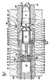
- the gun shown in FIG. 1 includes a receiver 10 having a longitudinally extending cavity 12 therein, whose forward end receives a gun barrel 14 and whose aft end receives a breech obturator 16.
- the barrel and the obturator are each releasably secured to the receiver by conventional means, here shown as threads.
- the obturator may be advanced into the cavity 12 more or less as desired to vary its internal open volume or it may remain fixed and the initial chamber volume allowed to vary as the charge is varied.
- a projectile 17 may be inserted into the projectile chamber 18 of the gun barrel 14, which barrel may have a conventional forcing cone 20 and rifling 22.
- Projectiles may be sequentially fed and chambered by an appropriate loading mechanism which is not shown here; but see, for example, U.S. Patent 4,244,270, issued to D. P. Tassie on Jan. 13, 1981.
- the gun barrel 14, the cavity 12, and the obturator 16 are shown as mutually coaxial, i.e., "in-line,” on the longitudinal axis 24 of the gun.
- other non-coaxial configurations of the invention may be constructed in which the injection elements are in an alternative relationship to the barrel.
- An outer, differential area, controlled piston 26 has an aft tubular body 28 which rides within an annular cavity 30 defined by the inner wall of the cavity 12 and the outer wall 32 of a reduced diameter forward portion 34 of the obturator 16.
- the piston 26 has a forward annular head 36 having a forward annular face 38 of relatively large cross-sectional area, an aft annular face 40 of relatively small cross-sectional area and a conical opening 42.
- An inner, differential area, controlling piston 44 has an aft cylindrical body 46 which rides within a cylindrical cavity 48 having a side wall 50 and a base wall 52 in the obturator 16.
- the body 46 has an aft face 47 and carries an annular seal 54 which seals against the side wall 50 to close, with aft face 47, the cavity 48.
- the piston 44 has a forward frusto-conical head 56 having a forward circular face 58 of relatively large cross-sectional area, an aft annular face 60 of relatively small cross-sectional area, and a conical side wall 62 which mates with the conical opening 42.
- the combustion chamber 63 is defined by the aft face of the projectile 17, the piston forward faces 58 and 38, and the inner wall of the cavity 12.
- the obturator 16 also includes an internal cylindrical cavity 64 having a sidewall 66, a forward wall 68 and a base wall 70.
- a longitudinal bore 72 extends between the faces 52 and 68.
- a piston 74 is disposed within the cavity 64 and has an annular seal 76 which seals against the side wall 66 to divide the cavity 64 into a forward portion 64F and an aft portion 64A.
- a rod 77 is fixed to and between the controlling piston 44 and the piston 74 and passes through the bore 72.
- a seal 78 is fixed in the bore 72 and seals against the rod 77.
- a control valve mechanism here shown as two valves 80a and 80b, is also respectively connected to and between the faces 52 and 68 to permit the flow of hydraulic fluid between the cavity 48 and the cavity 64F.
- the orifice area in each control valve may be variably controlled through a respective control passageway 82a and 82b so as to variably limit the mass rate of flow of hydraulic fluid between the cavities 48 and 64F.
- the control valve may be pressure controlled, spring return, where the pressure in the control passageway is controlled by a cam operated spool valve assembly as shown in U.S. Patent 3,763,739 issued to D. P. Tassie on Oct. 9, 1973.
- the cavity 84 serves as the liquid propellant reservoir or propellant pumping chamber; and is filled through a passageway 86 having a checkvalve 88, both in the obturator 16.
- the volume of this reservoir 84 is determined by length that the obturator 16 has been set into the cavity 12 of the receiver 10. Alternatively, a lesser volume can be determined by limiting the joint forward travel of the two pistons to less than full forward.
- a latch mechanism to hold the outer piston 26, and with it, the inner piston 44, fully seated in its aft disposition on the forward portion 34 of the obturator 16, may include an annular notch 90 in the outer piston 26 and a pressure controlled, spring return detent 92 having a control passageway 94, whose pressure may be controlled by a cam operated spool valve assembly.
- An annular cavity 100 may be provided around the outer piston 26 which may be prefilled with hydraulic fluid via a passageway 102 with a check valve 104 to provide hydraulic support to the annular wall of the piston during firing. This cavity may also receive additives, if desired, to be passed into the combustion chamber 63 during the aftward stroke of the outer piston 26. Alternatively, the cavity 100 may be omitted.
- a source 110 of initial combustion gas is coupled by a passageway 112, which may have a check valve 114, into the combustion chamber 63 to provide and initial supply of gas under pressure in the combustion chamber to initiate the aftward stroke of the controlling piston 44, to apply pressure to the liquid propellant in the pumping chamber 84 and thereafter to open the injection orifice defined by the conical surfaces 42 and 62.
- This source may be an electrically fired primer, which is replaced as each projectile is chambered; or it may be an electrically fired liquid propellant intiator, or it may be an adiabatic igniter as shown in US 4,231,282 issued to E. Ashley on Nov. 4, 1980.
- FIG. 5 A simplified version of the hydraulic damping control of FIG. 1 is shown in FIG. 5.
- the damping, variable area, orifice 80 ⁇ equivalent to 80a or 80b, is defined by an annular opening 120 formed in the breech obturator 16 ⁇ and a contoured stem 122 which extends aftwardly from the controlling piston 44 ⁇ .
- the diameter of the stem adjacent the opening 120 determines the area of the orifice.
- the orifice area will be minimized towards the end of the aftward stroke of the controlling piston 44 ⁇ to bring both it and the controlled piston 26 ⁇ to a soft stop into rear dwell.
- FIG. 1 shows one mechanism for refilling liquid propellant into the pumping chamber.
- the controlled piston 26 reaches the end of its aft stroke its notch 90 is captured by the latch 92 to hold that piston 26, and thereby the controlling piston 44, in aft dwell.
- the latch 92 is released, or overcome by propellant loading pressure, to move both pistons together, with the injection orifice closed, forwardly to the end of their forward stroke. Captured gas under pressure in the cavity 64A may be utilized to insure that the controlling piston 44 moves with the controlled piston 26 to keep the injection orifice closed.
- FIG. 1 also shows a rib 140 extending radially from the forward face 58 of the controlling piston 44. This rib is maintained in a substantially fixed position relative to the injection orifice throughout the firing stroke and serves to disperse or break up the flowing sheet of the propellant throughout the combustion chamber.
- the obturator 16 may be advanced more or less into the receiver 10 to decrease or to increase the volume of the pumping chamber 84 and thereby the volume of propellant admitted into the pumping chamber.
- FIG. 2 shows the outer differential area piston 200 serving as the controlling piston, and the inner differential area piston 202 serving as the controlled piston.
- the motion of the controlling piston 200 is controlled by a variable hydraulic control circuit 204 coupling annular cavities 206 and 208.
- the annular stem 210 of the piston 200 travels within the cavity 208 during the aft stroke of the piston and must displace the hydraulic fluid from the cavity 208 through the control circuit 204.
- a helical compression spring 212 is disposed on the stem of the piton 202 to hold this piston 202 against the piston 200 during the propellant loading process to maintain the injection orifice closed.
- the chamber in which the helical spring is shown may be hydraulically or pneumatically controlled to effect loading cycle control.
- a deflector such as rib 214 extending radially from the combustion chamber face of the controlling piston 200 may be used to serve as a break up device for the sheet of liquid propellant injected through the injection orifice.
- FIG. 3 shows a species which is similar to that of FIG. 1, except that the controlling inner piston 300 has a combustion chamber circular face 302 and a damping chamber annular face 304, but not any face on the pumping chamber 306.
- the second term of equation 4 is zero with respect to this species.
- FIG. 4 shows a species which is similar to that of FIG. 2 except that the controlling outer piston 400 has a combustion chamber annular face 402 and a damping chamber annular face 404, but not any face on the pumping chamber 406.
- the second term of equation 4 is zero with respect to this species.
- the motion of the controlling piston is independent of the pressure fluctuations in the liquid propellant in the propellant pumping chamber.
- FIG. 6 shows another version of the hydraulic damping control of FIG. 1.
- the variable area damping orifice 352 equivalent to 80a and 80b, is defined by a series of orifices connected to a series of orifices 353 by a slot 342 located by front 340F and aftward 340A portions of cylindrical stem 340 which extends aftwardly from the controlling piston 330.
- the cylindrical stem 340 slides into a cylindrical bore 341 provided in the breech obturator 346.
- the slot 342 also moves and connects the variable area damper orifices 352 to the variable area orifices 353.
- variable area orifices 352 are connected to cavity 350 by the passageway 351 and the variable area orifices 353 are connected by the passageway 354.
- the damper orifice area will be minimized towards the end of the aftward stroke of the controlling piston 330 to bring both it and the controlled piston 331 to a soft stop into rear dwell.
- the damper orifice area can be varied by opening or closing the orifices 352.
- a passageway 343 is provided to fill hydraulic fluid into the damper cavity 350.
Applications Claiming Priority (2)
| Application Number | Priority Date | Filing Date | Title |
|---|---|---|---|
| US06/879,723 US4693165A (en) | 1986-06-27 | 1986-06-27 | Liquid propellant gun |
| US879723 | 1986-06-27 |
Publications (3)
| Publication Number | Publication Date |
|---|---|
| EP0250978A2 true EP0250978A2 (de) | 1988-01-07 |
| EP0250978A3 EP0250978A3 (en) | 1988-08-31 |
| EP0250978B1 EP0250978B1 (de) | 1991-10-16 |
Family
ID=25374750
Family Applications (1)
| Application Number | Title | Priority Date | Filing Date |
|---|---|---|---|
| EP87108490A Expired EP0250978B1 (de) | 1986-06-27 | 1987-06-12 | Rohrwaffe mit Flüssigkeitstreibmittel |
Country Status (6)
| Country | Link |
|---|---|
| US (1) | US4693165A (de) |
| EP (1) | EP0250978B1 (de) |
| JP (1) | JPH0746038B2 (de) |
| CA (1) | CA1285800C (de) |
| DE (1) | DE3773760D1 (de) |
| IL (1) | IL82470A (de) |
Cited By (1)
| Publication number | Priority date | Publication date | Assignee | Title |
|---|---|---|---|---|
| FR2697624A1 (fr) * | 1992-11-02 | 1994-05-06 | Giat Ind Sa | Système d'alimentation d'un dispositif par un volume de liquide hydraulique ayant une valeur prédéterminée variant en fonction des conditions opératoires. |
Families Citing this family (11)
| Publication number | Priority date | Publication date | Assignee | Title |
|---|---|---|---|---|
| US4852459A (en) * | 1987-12-16 | 1989-08-01 | General Electric Company | Liquid propellant weapon system |
| DE3805621A1 (de) * | 1988-02-24 | 1991-11-28 | Rheinmetall Gmbh | Maschinenkanone fuer monergole fluessigtreibmittel |
| DE3816663A1 (de) * | 1988-05-17 | 1989-11-23 | Diehl Gmbh & Co | Rohrwaffe mit regenerativer treibmitteleinspritzung |
| DE3820492A1 (de) * | 1988-06-16 | 1989-12-28 | Diehl Gmbh & Co | Rohrwaffe mit chemisch-elektrischem hybridantrieb mittels regenerativer treibmitteleinspritzung |
| US4934242A (en) * | 1988-12-18 | 1990-06-19 | General Electric Company | Liquid propellant gun for projectiles of different masses and velocities |
| DE4020673A1 (de) * | 1990-06-29 | 1992-01-09 | Rheinmetall Gmbh | Vorrichtung zur kompaktumsetzung von fluessigtreibstoff in kanonen |
| US5639117A (en) * | 1996-06-05 | 1997-06-17 | Lockheed Martin Corporation | Vehicle occupant restraint apparatus |
| US6036226A (en) * | 1997-02-03 | 2000-03-14 | General Dynamics Armament Systems, Inc. | Inflator capable of modulation air bag inflation rate in a vehicle occupant restraint apparatus |
| US6039347A (en) * | 1997-02-03 | 2000-03-21 | General Dynamics Armament Systems, Inc. | Liquid propellant airbag inflator with dual telescoping pistons |
| US5829784A (en) * | 1997-02-13 | 1998-11-03 | General Dynamics Armament Systems, Inc. | Airbag inflator for vehicle occupant restraint apparatus |
| US9222737B1 (en) * | 2008-05-20 | 2015-12-29 | Lund And Company Inventions, Llc | Projectile launcher |
Citations (2)
| Publication number | Priority date | Publication date | Assignee | Title |
|---|---|---|---|---|
| US2981153A (en) * | 1952-11-14 | 1961-04-25 | Texaco Experiment Inc | Fuel injection device |
| US4341147A (en) * | 1980-06-16 | 1982-07-27 | General Electric Company | Coaxial dual hollow piston regenerative liquid propellant gun |
Family Cites Families (4)
| Publication number | Priority date | Publication date | Assignee | Title |
|---|---|---|---|---|
| US4231282A (en) * | 1979-03-29 | 1980-11-04 | General Electric Company | Ignition system |
| US4523507A (en) * | 1983-11-02 | 1985-06-18 | General Electric Company | In-line annular piston fixed bolt regenerative liquid propellant gun |
| US4523508A (en) * | 1983-11-02 | 1985-06-18 | General Electric Company | In-line annular piston fixed bolt regenerative liquid propellant gun |
| US4586422A (en) * | 1984-04-10 | 1986-05-06 | General Electric Company | In-line annular piston fixed bolt regenerative variable charge liquid propellant gun with variable hydraulic control of piston |
-
1986
- 1986-06-27 US US06/879,723 patent/US4693165A/en not_active Expired - Lifetime
-
1987
- 1987-05-10 IL IL82470A patent/IL82470A/xx not_active IP Right Cessation
- 1987-06-12 EP EP87108490A patent/EP0250978B1/de not_active Expired
- 1987-06-12 DE DE8787108490T patent/DE3773760D1/de not_active Expired - Fee Related
- 1987-06-23 JP JP62154619A patent/JPH0746038B2/ja not_active Expired - Fee Related
- 1987-06-25 CA CA000540597A patent/CA1285800C/en not_active Expired - Fee Related
Patent Citations (2)
| Publication number | Priority date | Publication date | Assignee | Title |
|---|---|---|---|---|
| US2981153A (en) * | 1952-11-14 | 1961-04-25 | Texaco Experiment Inc | Fuel injection device |
| US4341147A (en) * | 1980-06-16 | 1982-07-27 | General Electric Company | Coaxial dual hollow piston regenerative liquid propellant gun |
Cited By (3)
| Publication number | Priority date | Publication date | Assignee | Title |
|---|---|---|---|---|
| FR2697624A1 (fr) * | 1992-11-02 | 1994-05-06 | Giat Ind Sa | Système d'alimentation d'un dispositif par un volume de liquide hydraulique ayant une valeur prédéterminée variant en fonction des conditions opératoires. |
| WO1994010522A1 (fr) * | 1992-11-02 | 1994-05-11 | Giat Industries | Amortissement du piston d'un canon a charge propulsive liquide |
| US5533434A (en) * | 1992-11-02 | 1996-07-09 | Giat Industries | Method and system for supplying a device with a volume of hydraulic fluid whose predetermined value according to operating conditions |
Also Published As
| Publication number | Publication date |
|---|---|
| CA1285800C (en) | 1991-07-09 |
| DE3773760D1 (de) | 1991-11-21 |
| EP0250978B1 (de) | 1991-10-16 |
| US4693165A (en) | 1987-09-15 |
| IL82470A0 (en) | 1987-11-30 |
| JPH0746038B2 (ja) | 1995-05-17 |
| EP0250978A3 (en) | 1988-08-31 |
| JPS6334496A (ja) | 1988-02-15 |
| IL82470A (en) | 1993-07-08 |
Similar Documents
| Publication | Publication Date | Title |
|---|---|---|
| US4341147A (en) | Coaxial dual hollow piston regenerative liquid propellant gun | |
| US4745841A (en) | Liquid propellant gun | |
| US6095051A (en) | Self loading gun cartridge | |
| US4043248A (en) | Liquid propellant gun (recoilless regenerative piston) | |
| US4063486A (en) | Liquid propellant weapon system | |
| EP0161448B1 (de) | Regenerative Feuerwaffe mit flüssiger veränderbarer Treibladung | |
| US4693165A (en) | Liquid propellant gun | |
| US4819610A (en) | Device for feeding weapons with compressed gas | |
| US4867038A (en) | Recoil brake for a gun | |
| US4132149A (en) | Liquid propellant weapon system | |
| US4523507A (en) | In-line annular piston fixed bolt regenerative liquid propellant gun | |
| US4126078A (en) | Liquid propellant weapon system | |
| US4934242A (en) | Liquid propellant gun for projectiles of different masses and velocities | |
| US4726184A (en) | Rocket engine assembly | |
| US4949621A (en) | Liquid propellant gun | |
| US3992976A (en) | Liquid propellant gun | |
| US4722185A (en) | Double piston rocket engine assembly | |
| US4967638A (en) | Liquid propellant weapon system | |
| US5381722A (en) | Liquid propellant weapon | |
| US4069739A (en) | Liquid propellant weapon systems | |
| US4907511A (en) | Liquid propellant gun | |
| US6044746A (en) | Projectile propulsion assembly that limits recoil force | |
| US5131313A (en) | Linear accelerator | |
| US4945809A (en) | Liquid propellant gun | |
| US4932327A (en) | Liquid propellant gun |
Legal Events
| Date | Code | Title | Description |
|---|---|---|---|
| PUAI | Public reference made under article 153(3) epc to a published international application that has entered the european phase |
Free format text: ORIGINAL CODE: 0009012 |
|
| AK | Designated contracting states |
Kind code of ref document: A2 Designated state(s): BE CH DE FR GB IT LI SE |
|
| PUAL | Search report despatched |
Free format text: ORIGINAL CODE: 0009013 |
|
| AK | Designated contracting states |
Kind code of ref document: A3 Designated state(s): BE CH DE FR GB IT LI SE |
|
| 17P | Request for examination filed |
Effective date: 19890120 |
|
| 17Q | First examination report despatched |
Effective date: 19900212 |
|
| GRAA | (expected) grant |
Free format text: ORIGINAL CODE: 0009210 |
|
| AK | Designated contracting states |
Kind code of ref document: B1 Designated state(s): BE CH DE FR GB IT LI SE |
|
| ET | Fr: translation filed | ||
| ITF | It: translation for a ep patent filed |
Owner name: ING. C. GREGORJ S.P.A. |
|
| REF | Corresponds to: |
Ref document number: 3773760 Country of ref document: DE Date of ref document: 19911121 |
|
| PLBE | No opposition filed within time limit |
Free format text: ORIGINAL CODE: 0009261 |
|
| STAA | Information on the status of an ep patent application or granted ep patent |
Free format text: STATUS: NO OPPOSITION FILED WITHIN TIME LIMIT |
|
| 26N | No opposition filed | ||
| EAL | Se: european patent in force in sweden |
Ref document number: 87108490.1 |
|
| PGFP | Annual fee paid to national office [announced via postgrant information from national office to epo] |
Ref country code: FR Payment date: 19960515 Year of fee payment: 10 |
|
| PGFP | Annual fee paid to national office [announced via postgrant information from national office to epo] |
Ref country code: BE Payment date: 19960528 Year of fee payment: 10 |
|
| PGFP | Annual fee paid to national office [announced via postgrant information from national office to epo] |
Ref country code: GB Payment date: 19960529 Year of fee payment: 10 |
|
| PG25 | Lapsed in a contracting state [announced via postgrant information from national office to epo] |
Ref country code: GB Free format text: LAPSE BECAUSE OF NON-PAYMENT OF DUE FEES Effective date: 19970612 |
|
| PG25 | Lapsed in a contracting state [announced via postgrant information from national office to epo] |
Ref country code: BE Effective date: 19970630 |
|
| BERE | Be: lapsed |
Owner name: GENERAL ELECTRIC CY Effective date: 19970630 |
|
| GBPC | Gb: european patent ceased through non-payment of renewal fee |
Effective date: 19970612 |
|
| PG25 | Lapsed in a contracting state [announced via postgrant information from national office to epo] |
Ref country code: FR Free format text: LAPSE BECAUSE OF NON-PAYMENT OF DUE FEES Effective date: 19980227 |
|
| REG | Reference to a national code |
Ref country code: FR Ref legal event code: ST |
|
| REG | Reference to a national code |
Ref country code: FR Ref legal event code: ST |
|
| PGFP | Annual fee paid to national office [announced via postgrant information from national office to epo] |
Ref country code: SE Payment date: 20030619 Year of fee payment: 17 |
|
| PGFP | Annual fee paid to national office [announced via postgrant information from national office to epo] |
Ref country code: CH Payment date: 20030623 Year of fee payment: 17 |
|
| PGFP | Annual fee paid to national office [announced via postgrant information from national office to epo] |
Ref country code: DE Payment date: 20030630 Year of fee payment: 17 |
|
| PG25 | Lapsed in a contracting state [announced via postgrant information from national office to epo] |
Ref country code: SE Free format text: LAPSE BECAUSE OF NON-PAYMENT OF DUE FEES Effective date: 20040613 |
|
| PG25 | Lapsed in a contracting state [announced via postgrant information from national office to epo] |
Ref country code: LI Free format text: LAPSE BECAUSE OF NON-PAYMENT OF DUE FEES Effective date: 20040630 Ref country code: CH Free format text: LAPSE BECAUSE OF NON-PAYMENT OF DUE FEES Effective date: 20040630 |
|
| PG25 | Lapsed in a contracting state [announced via postgrant information from national office to epo] |
Ref country code: DE Free format text: LAPSE BECAUSE OF NON-PAYMENT OF DUE FEES Effective date: 20050101 |
|
| EUG | Se: european patent has lapsed | ||
| EUG | Se: european patent has lapsed | ||
| REG | Reference to a national code |
Ref country code: CH Ref legal event code: PL |
|
| PG25 | Lapsed in a contracting state [announced via postgrant information from national office to epo] |
Ref country code: IT Free format text: LAPSE BECAUSE OF NON-PAYMENT OF DUE FEES;WARNING: LAPSES OF ITALIAN PATENTS WITH EFFECTIVE DATE BEFORE 2007 MAY HAVE OCCURRED AT ANY TIME BEFORE 2007. THE CORRECT EFFECTIVE DATE MAY BE DIFFERENT FROM THE ONE RECORDED. Effective date: 20050612 |