EP0250939B1 - Séchoir à filtre de laboratoire à vide - Google Patents
Séchoir à filtre de laboratoire à vide Download PDFInfo
- Publication number
- EP0250939B1 EP0250939B1 EP87108249A EP87108249A EP0250939B1 EP 0250939 B1 EP0250939 B1 EP 0250939B1 EP 87108249 A EP87108249 A EP 87108249A EP 87108249 A EP87108249 A EP 87108249A EP 0250939 B1 EP0250939 B1 EP 0250939B1
- Authority
- EP
- European Patent Office
- Prior art keywords
- container
- filter
- dryer according
- rotor
- suction filter
- Prior art date
- Legal status (The legal status is an assumption and is not a legal conclusion. Google has not performed a legal analysis and makes no representation as to the accuracy of the status listed.)
- Expired - Lifetime
Links
- 239000000047 product Substances 0.000 claims description 60
- 238000001914 filtration Methods 0.000 claims description 35
- 238000005406 washing Methods 0.000 claims description 35
- 238000001035 drying Methods 0.000 claims description 18
- 239000000725 suspension Substances 0.000 claims description 9
- 238000010438 heat treatment Methods 0.000 claims description 6
- 239000000463 material Substances 0.000 claims description 6
- 239000002184 metal Substances 0.000 claims description 6
- 238000000034 method Methods 0.000 claims description 6
- 238000002425 crystallisation Methods 0.000 claims description 5
- 229920003023 plastic Polymers 0.000 claims description 3
- 239000004033 plastic Substances 0.000 claims description 3
- 238000001816 cooling Methods 0.000 claims description 2
- 238000005245 sintering Methods 0.000 claims description 2
- 239000012265 solid product Substances 0.000 claims description 2
- 239000007921 spray Substances 0.000 claims description 2
- 239000012530 fluid Substances 0.000 claims 3
- 238000002955 isolation Methods 0.000 claims 2
- 238000005056 compaction Methods 0.000 claims 1
- 239000007788 liquid Substances 0.000 description 19
- 239000007789 gas Substances 0.000 description 10
- 239000012452 mother liquor Substances 0.000 description 8
- 238000009826 distribution Methods 0.000 description 6
- 230000000694 effects Effects 0.000 description 6
- 230000008025 crystallization Effects 0.000 description 4
- 238000002156 mixing Methods 0.000 description 4
- 238000004140 cleaning Methods 0.000 description 3
- 238000007906 compression Methods 0.000 description 3
- 238000000855 fermentation Methods 0.000 description 3
- 230000004151 fermentation Effects 0.000 description 3
- 238000009499 grossing Methods 0.000 description 3
- 239000013078 crystal Substances 0.000 description 2
- 239000004744 fabric Substances 0.000 description 2
- 238000011049 filling Methods 0.000 description 2
- 239000011148 porous material Substances 0.000 description 2
- 239000000126 substance Substances 0.000 description 2
- 230000006978 adaptation Effects 0.000 description 1
- QVGXLLKOCUKJST-UHFFFAOYSA-N atomic oxygen Chemical compound [O] QVGXLLKOCUKJST-UHFFFAOYSA-N 0.000 description 1
- 230000005540 biological transmission Effects 0.000 description 1
- 230000015572 biosynthetic process Effects 0.000 description 1
- 230000006835 compression Effects 0.000 description 1
- 230000008021 deposition Effects 0.000 description 1
- 238000007598 dipping method Methods 0.000 description 1
- 239000000428 dust Substances 0.000 description 1
- 230000002349 favourable effect Effects 0.000 description 1
- 239000012456 homogeneous solution Substances 0.000 description 1
- 230000001771 impaired effect Effects 0.000 description 1
- 238000009413 insulation Methods 0.000 description 1
- 238000012423 maintenance Methods 0.000 description 1
- 238000004519 manufacturing process Methods 0.000 description 1
- 238000005360 mashing Methods 0.000 description 1
- 239000000203 mixture Substances 0.000 description 1
- 239000001301 oxygen Substances 0.000 description 1
- 229910052760 oxygen Inorganic materials 0.000 description 1
- 235000011837 pasties Nutrition 0.000 description 1
- 239000000825 pharmaceutical preparation Substances 0.000 description 1
- 229940127557 pharmaceutical product Drugs 0.000 description 1
- 239000000843 powder Substances 0.000 description 1
- 238000003825 pressing Methods 0.000 description 1
- 230000002441 reversible effect Effects 0.000 description 1
- 230000035939 shock Effects 0.000 description 1
- 239000007787 solid Substances 0.000 description 1
- 238000011144 upstream manufacturing Methods 0.000 description 1
Images
Classifications
-
- B—PERFORMING OPERATIONS; TRANSPORTING
- B01—PHYSICAL OR CHEMICAL PROCESSES OR APPARATUS IN GENERAL
- B01D—SEPARATION
- B01D35/00—Filtering devices having features not specifically covered by groups B01D24/00 - B01D33/00, or for applications not specifically covered by groups B01D24/00 - B01D33/00; Auxiliary devices for filtration; Filter housing constructions
- B01D35/18—Heating or cooling the filters
-
- B—PERFORMING OPERATIONS; TRANSPORTING
- B01—PHYSICAL OR CHEMICAL PROCESSES OR APPARATUS IN GENERAL
- B01D—SEPARATION
- B01D33/00—Filters with filtering elements which move during the filtering operation
- B01D33/01—Filters with filtering elements which move during the filtering operation with translationally moving filtering elements, e.g. pistons
- B01D33/03—Filters with filtering elements which move during the filtering operation with translationally moving filtering elements, e.g. pistons with vibrating filter elements
- B01D33/0346—Filters with filtering elements which move during the filtering operation with translationally moving filtering elements, e.g. pistons with vibrating filter elements with flat filtering elements
- B01D33/0376—Filters with filtering elements which move during the filtering operation with translationally moving filtering elements, e.g. pistons with vibrating filter elements with flat filtering elements supported
- B01D33/0392—Filters with filtering elements which move during the filtering operation with translationally moving filtering elements, e.g. pistons with vibrating filter elements with flat filtering elements supported with curved filtering elements
-
- B—PERFORMING OPERATIONS; TRANSPORTING
- B01—PHYSICAL OR CHEMICAL PROCESSES OR APPARATUS IN GENERAL
- B01D—SEPARATION
- B01D33/00—Filters with filtering elements which move during the filtering operation
- B01D33/44—Regenerating the filter material in the filter
- B01D33/46—Regenerating the filter material in the filter by scrapers, brushes nozzles or the like acting on the cake-side of the filtering element
- B01D33/466—Regenerating the filter material in the filter by scrapers, brushes nozzles or the like acting on the cake-side of the filtering element scrapers
-
- B—PERFORMING OPERATIONS; TRANSPORTING
- B01—PHYSICAL OR CHEMICAL PROCESSES OR APPARATUS IN GENERAL
- B01D—SEPARATION
- B01D33/00—Filters with filtering elements which move during the filtering operation
- B01D33/58—Handling the filter cake in the filter for purposes other than for regenerating the filter cake remaining on the filtering element
- B01D33/60—Handling the filter cake in the filter for purposes other than for regenerating the filter cake remaining on the filtering element for washing
-
- B—PERFORMING OPERATIONS; TRANSPORTING
- B01—PHYSICAL OR CHEMICAL PROCESSES OR APPARATUS IN GENERAL
- B01D—SEPARATION
- B01D33/00—Filters with filtering elements which move during the filtering operation
- B01D33/58—Handling the filter cake in the filter for purposes other than for regenerating the filter cake remaining on the filtering element
- B01D33/62—Handling the filter cake in the filter for purposes other than for regenerating the filter cake remaining on the filtering element for drying
- B01D33/66—Handling the filter cake in the filter for purposes other than for regenerating the filter cake remaining on the filtering element for drying by gases or by heating
- B01D33/666—Handling the filter cake in the filter for purposes other than for regenerating the filter cake remaining on the filtering element for drying by gases or by heating by indirect heat-exchange
-
- B—PERFORMING OPERATIONS; TRANSPORTING
- B01—PHYSICAL OR CHEMICAL PROCESSES OR APPARATUS IN GENERAL
- B01D—SEPARATION
- B01D33/00—Filters with filtering elements which move during the filtering operation
- B01D33/58—Handling the filter cake in the filter for purposes other than for regenerating the filter cake remaining on the filtering element
- B01D33/68—Retarding cake deposition on the filter during the filtration period, e.g. using stirrers
Definitions
- the invention relates to a suction filter dryer, in particular for isolating and drying solid products from suspensions, consisting of a closed container and a filter chamber formed between an outer wall and a filter surface arranged at a distance therefrom, which are controlled by controlled, optionally to a vacuum, compressed gas. or washing liquid source connected distribution lines.
- a barrel or drum-shaped container is attached in cross-section approximately diagonally to a horizontal shaft, by the rotation of which the container and the product filled therein are driven to tumble during drying .
- the container is provided on one side with a dome-like protuberance, which is closed off towards the container by a filter surface, behind which a filter chamber is formed with the outside of the dome.
- other valve-controlled pipelines are also passed through the hollow shaft, through which powdery liquid and / or gaseous substances, e.g. B. are passed for washing or for evacuation in the container. Any substance required for processing the product can thus be placed intermittently or continuously in the container of the known apparatus are introduced or removed, specifically before, during or after washing, mixing, filtering and / or heating / subcooling the product to be dried.
- the invention has for its object to design and improve a suction filter drier of the type mentioned in such a way that no cracks in the product cake, or as little as possible, impair these operations during operation during filtering, washing and drying.
- This object is achieved in that the container has a horizontal main axis, its jacket mainly in the lower half of the container from the concave, in particular cylindrical to the main axis curved filter surface and from the outer wall running at a distance therefrom, while the distance between them in a plurality Axial filter chambers is divided, and that a rotor extending in the axial direction in the container, a plurality of juxtaposed, radially directed, in particular heated disks or disk segments carrying and containing circulation lines for homogenizing the product cake during filtration or for washing and drying the product after insulation is connected to a drive for oscillating or reversible rotary movements.
- This design eliminates the fundamental disadvantage of flat filter surfaces, which leave cracks and channels in the cake during filtration, due to the fact that they are used later Washing liquid flows through without washing the neighboring cake sections free of mother liquor.
- the concavely curved filter surface enables undisturbed cake formation largely without cracks, since the weight of the product cake reaching up to the middle of the container pushes downwards along the curved filter surface and the resulting cracks are constantly closed again.
- This self-compression of the product cake is favored by low friction on the filter surface made of metal or plastic and by a smooth surface of the rotor. Thus, the product cake can still be washed carefully with a minimum amount of washing liquid.
- the proposed filtration apparatus allows a versatile adaptation to different operating conditions and processes that result from the processing of different types of products.
- the respective filter surfaces can be acted upon with a positive pressure in the container and external vacuum as well as with external positive pressure and with vacuum or normal pressure in the container via a distribution line system leading to the filter chambers and optionally connectable vacuum or compressed gas sources.
- the filter surfaces can consist of metal fabrics connected by sintering or of sintered material, plastic or other filter material combined with metal fabrics. If the distribution lines via valves from an electronic measuring and control system are controllable, the different suction pressure requirements of the lowest filter chamber compared to the lateral filter chambers can be taken into account, for example. Just as excess suspension or washing liquid is sucked off via the filter, conversely, the filter surfaces can be acted upon by a washing liquid source via the distribution line system and spray nozzles of a washing liquid line opening there can be provided for simultaneous flooding of the container.
- approximately half of the end faces of the container can be designed as inclined filter surfaces with filter chambers arranged behind them, which adjoin the circumference to the curved filter surface of the jacket. In this way it is prevented that the product cake detaches from vertical end walls and the product remains unwashed in the end regions of the container and the washing liquid would seep away and be sucked away unused.
- the rotor consists of a hollow body with a flattened, in particular oval or elliptical cross-section, which in filtration operation is driven from a flat starting position by reversing pivoting movements between approximately 15 ° and 30 ° and compresses the product cake without a smoothing effect.
- This acts in addition to the self-compacted dead weight of the product due to the curved filter surface, the slight pressure movement of the relatively wide rotor, which acts on the upper and distant product layers with its slight pivoting movement.
- This compression of the product cake which occurs during the reversing pivoting movement of the rotor, homogenizes the product cake and closes pores and cracks formed there when the mother liquor is suctioned off.
- a gap is formed between the rotor and the compacted cake, in which washing liquid subsequently introduced into the container is taken up and distributed over the cake surface.
- the rotor expediently carries, on a flattened side, disk segments next to one another, which extend symmetrically over an arc up to approximately 150 ° and have radial end faces to support the recompression of the product cake during the pivoting movements of the rotor.
- blades attached to each disc segment can also be effective as a radially outer continuation of the respective end face.
- a plurality of scraper blades are provided next to each other, each of which extends between the adjacent disks or disk segments and, in particular, can be pivoted together on a pivot shaft mounted in the vicinity of the container shell into a rest position close to the container circumference.
- the hollow or with inner baffles for a heating medium disc segments can be connected to circulation lines in the rotor, and there is also the possibility to at least partially design the surfaces of the disc segments as filter surfaces and to apply suction pressure or drying gas via distribution lines within the rotor.
- the disc segments during subsequent drying or mashing have the task of mixing the product either by reversing or rotating in one direction.
- the disc segments also serve for accelerated drying if, for example, they are designed in part as contact dryer surfaces through which the heating medium flows and as filter surfaces.
- the rotor is attached to a rotor shaft which is overhung in a machine stand
- the container can be loaded or emptied from the free end side.
- the container can then be removed from the rotor for cleaning and maintenance.
- the container can also be mounted on the fly by being mounted with a bearing sleeve extending from its one end face on the rotor shaft projecting from a machine stand so that it can be pivoted by at least 180 °.
- the filter chambers act as gas filters via the curved filter surface portions, which are cleaned by means of pressure gas surges attached from the outside.
- the blades for product transport have an angle of attack in the longitudinal direction of the container and a streamlined shape on their rear side.
- the disks or disk segments are able to convey the product from one end of the container to the other, and thus also over the middle, where a closable product outlet can then be provided for the automatic emptying of the container.
- the dried product can be almost completely emptied automatically via a lower product outlet.
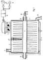
- the double jacket is arranged in the lower half of the horizontal cylinder container according to FIG. 1 and is delimited on the inside by a filter surface 24 and divided into segments which can be controlled individually with regard to the vacuum applied.
- the container can receive 1 overpressure.
- First the container is filled with suspension and later refilled depending on its solids content.
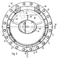
- the filter surface 24 is divided into several filter chambers 11 to 15, which can be seen in the example of FIG. 3.
- the filter chambers are controlled uniformly or differentially. In order to achieve a flat cake surface from which the mother liquor floating above it can also be suctioned off laterally, only the lower filter chamber 13 may be effective after a certain period of time.
- a trough-shaped product layer forms on the surface.
- a vacuum measuring system is used to determine which filter surface is not covered by the product and which draws in more air than the others, the chamber of which is then immediately switched off.
- rotor disks 3 are fastened, the cross section of which is determined according to drying and filtration aspects.
- the product is held homogeneously in the narrow area between adjacent rotor disks 3 by pendulum movements of the rotor of a few angular degrees and is not locally compacted. Due to the outwardly tapering cross section of the rotor disks, a force effect parallel to the curved filter surface 24 is created.
- Schaufein 5 attached to the circumference of the rotor disks remain during the filtration process outside the cake in the upper half of the container, in which an inlet connection 4 and a filter dome 7 can be provided according to FIG. 1, to which a condenser 10, an exhaust gas fan 8 and a vacuum pump 9 are connected .
- the filtration apparatus can be used in various ways with the same aim of achieving a product with a washing quality similar to that of a centrifuge in the shortest possible time.
- the container can be flooded by means of a washing nozzle line, not shown, while at the same time washing liquid is pressed into the cake from the outside through the filter surface 24 via the filter chambers.
- the cake moistened from both sides is intimately mixed with washing liquid by pendulum or rotary movements of the rotor disks and the blades 5.
- the rotor disks 3 which act, for example, as cooling surfaces in this process stage, are cleaned from crystal deposits which form during each revolution by stationary scrapers 6, of which only one is shown in accordance with FIG. 1 for the sake of clarity is, but all sit on a common axis-parallel pivot shaft and can be pivoted into a rest position adjacent to the container wall.
- a suitable convection medium can be applied to the rotor disks and the rotor shaft via the circulation connection 20 outside the shaft bearing 23.
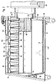
- the container is rotated through 180 ° about its longitudinal axis, so that the product no longer rests on the filter surface 24 but on a semi-cylindrical inner wall 40 arranged in its continuation which forms a double jacket with the outer wall 42 of the container.
- the product is dried by heating the rotor, the double jacket 40-42 divided into segments by axially extending separating strips and / or the disk segments 58 arranged on the rotor 54.
- dust is prevented from escaping from the product.
- the filter area divided by segment chambers 24 can be cleaned from the outside by a pressure gas shock.
- suction ports 52 provided in the end wall 50 and leading into the filter chambers 11 to 15 can be pressurized with compressed gas.
- the rotor shaft 54 containing the circulation channels 64 is surrounded within the container 1 by an eccentric, normally flat-lying oval rotor 56.
- coolable or heatable disk segments 58 are arranged, which, according to FIG. 3, extend approximately over a 150 ° bend and are held in the upper part of the container during the filtration.
- the hollow disk segments contain baffles 65 and are connected to the circulation channels of the rotor via openings 66 in the rotor jacket.
- the cake segment extending in the longitudinal direction of the container is compressed by a reversing pivoting movement of the flattened rotor 56 through an angle between approximately 15 ° to approximately 30 °, without an undesirable smoothing effect closing the pores occurring.
- a gap is formed between the rotor shaft and the compacted cake segment, which is desired and intended to subsequently take up washing liquid and to distribute it as evenly as possible over the entire cake surface.
- washing liquid is introduced through the filter chambers 11 to 15 and / or through washing lines 68, 69 containing two nozzles, not shown.
- the cake Due to the generally concave, in particular cylindrically curved filter surface, the cake is largely inevitably compressed, since it does not have the opportunity to evade the pressure exerted from above, as with flat filter bases. A partial turn of the rotor is sufficient to completely squeeze out the cake after the washing process and suction of the washing liquid. This takes place without blades 60 arranged at the ends of the disk segments 58 dipping into the product cake.
- the blades 60 can be arranged in continuation of the end faces of the disk segments 58.
- the rotor shaft 54 can already be heated during the filtration process, a fine powder layer will have formed on it before the rotation of the rotor shaft, which prevents the product cake from sticking there.
- the heated disc segments 58 also become active with a larger rotor swivel angle and can then also be used to further compact the product cake.
- the cake is compacted after the mother liquor has been sucked off, by rotating the rotor 56 by 15 ° to 30 °, so that the oval rotor and the approximately ring-shaped compact A gap is created in the cake surface, which is important for the even distribution of the refilled washing liquid.
- the rotor 56 is rotated with the disk segments 58 in order to initiate the drying process.
- a manufacturing process begins with the deposition of a crystalline phase from a previously homogeneous solution or also with the fermentation, with the various solution components in the container can be entered. If the products tend to cake during crystallization, the disc segments 58 are cleaned by wipers 62 that remain. On the other hand, the rotating disk segments 58, which can be heated during filtration and drying, provide a favorable mixing in order to accelerate the heat exchange.
- a gas cushion introduced through the filter chambers 11 to 15 can be built up, which avoids a passage of the suspension through the filter surface 24 and the caking of crystals and fluidizes the suspension during crystallization or fermentation, which also accelerates the heat exchange.
- oxygen can be blown in through the filter surfaces 24.
- the container 1 can be pulled off from the rotor shaft 54, which is mounted on the fly according to FIGS. 2 to 4, and its flange 38 is fastened to a connection plate 50 which is supported and supported in the machine stand 48. In this way, when changing the product, the cleaning of the rotor and the filter surfaces can be checked by eye after the container has been moved to the left on a roller guide (not shown) in FIG. 2.
- the container In order to protect the filter surface 24 from being impaired by the rotating blades 60 and to reduce the distance between the blades and the closed inner wall 40 after rotation of the container by 180 °, the container is offset eccentrically downward from the rotor axis by a dimension W shown in FIG. 3 .
- the closed inner wall 40 is unscrewed before the filter surface 24 is welded in.
- the blades 60 of the disk segments 58 are also turned so that a distance of only about 2 mm remains between the blade and the inner wall, which enables the dried goods to be completely removed when the container is pivoted through 180 ° through the closable opening 100 pointing downward.
- the opening 100 for filling in the suspension and for emptying the product is arranged in the longitudinal center of the container. If the blades 60 have opposite angles of attack on the disk segments on both sides of the opening 100, the product is conveyed from both ends of the container to the center by rotor rotation, where it accumulates and is mixed well. In the opposite direction of rotation, the material is redistributed, and this process can be repeated as required for mixing.
- the eccentricity described above and the small distance between the blades and the inner wall 40 enable complete emptying.
- a residual layer not covered by the blades is conveyed from the outside to the center by means of vibrators (not shown) arranged to the left and right of the opening 100 and by their opposite vibrations. At the same time, the vibrators used for emptying ensure that there are no cracks in the product cake during filtration and drying.
- the filtration apparatus can work as a continuous flow dryer when the position is pivoted through 180 °.
- the metal filter headliner is cleaned from the blades, provided that the product has not already fallen down. Fine cleaning can also be carried out with compressed gas bursts through the filter chambers.
- the blades, which are inclined in the conveying direction, have a pointed rear.
- approximately the lower half of the container end is designed as an inclined filter surface 44, behind which filter chambers 16, 18 provided with vacuum connections are provided, which adjoin the circumference of the curved filter surface 24 and are closed at the rear by the end wall 34, which is inclined here by 15 ° are.
- the cover plate 50 contains an equivalent bevel 46, which in the lower container area, similar to the opposite end, can be replaced by an inclined filter surface which extends up to approximately the height of the rotor 56, the cover plate 50 then being replaced by an oblique front wall would be replaced.
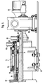
- the container swiveling device is integrated in the bearing and drive side of the filtration apparatus shown in FIG. 4.
- a bearing housing 72 is fastened on the machine stand 48 by means of screws 80.
- a bearing sleeve 70 which is firmly connected to the cover plate 50, is supported within the bearing housing 72 by means of roller bearings 76.
- the bearing sleeve 70 supports on its inside with the help of roller bearings 74 the rotor shaft 54, between its front end and the bearing sleeve 70 a multi-stage shaft seal 78 is provided.
- the rotor shaft 54 is driven by a continuously variable transmission 90 arranged on the machine stand 48 with an upstream motor 92.
- a locking cylinder 82 Firmly connected to the bearing housing 72 is a locking cylinder 82, the piston end 83 of which cooperates with a receptacle 84 of the bearing sleeve 70 in such a way that, for example, the piston pushed forward into the receptacle 84 by the spring force of the container in the filtration position according to FIG. 2 or in the pivoted position by 180 ° Drying and emptying position is held, which is assigned a second receptacle 84, not shown.
- a clutch cylinder 86 is fastened, the piston end of which cooperates with a receptacle 88 in the rotor shaft 54 in order to take the bearing sleeve 70 and thus the container with it to its pivoting by 180 ° or another movement when the piston is extended.
- the piston of the clutch cylinder 86 is moved back and the piston of the locking cylinder 82 is advanced again.
- the invention includes all types of filter surfaces with any curvature. It may be expedient to use an oval or elliptical or even corrugated filter surface in a cylindrical container, regardless of the shape of the container in the longitudinal direction.
Landscapes
- Chemical & Material Sciences (AREA)
- Chemical Kinetics & Catalysis (AREA)
- Drying Of Solid Materials (AREA)
Claims (21)
- Filtre sécheur à succion, en particulier, pour isoler et sécher des produits solides en suspension, constitué d'un récipient fermé et d'une chambre de filtration, formée entre une paroi extérieure et une surface de filtration qui est disposée à une certaine distance de cette dernière, récipient et chambre étant reliés à des canalisations de répartition commandées, raccordées ellesmême à une source de gaz sous pression ou sous vide, ou de liquide de lavage,
caractérisé en ce que le récipient (1) présente un axe principal horizontal, en ce que sa surface extérieure principalement dans la partie inférieure du récipient, est constituée de la surface de filtration (24) concave, en particulier courbée en forme de cylindre vers l'axe principal, ainsi que de la paroi extérieure (42) disposée à une certaine distance de celle-ci, tandis que la distance entre ces deux surfaces est séparée axialement en plusieurs chambres de filtration (11 à 18),
et en ce que, pour homogénéiser la gâteau de produit pendant la filtration ou pour laver et sécher le produit après séparation, un rotor (2; 56), disposé dans le récipient (1) suivant la direction axiale, portant un certain nombre de disques (3), ou d'éléments de disques (58), disposés à côté les uns des autres, dirigés radialement, en particulier de disques ou d'éléments de disque chauffants, et contenant des canalisations de circulation est raccordé à un entraînement assurant des mouvements de rotation pendulaires, ou réversibles. - Filtre sécheur à succion suivant la revendication 1, caractérisé en ce que, par l'intermédiaire d'un système de conduites de répartition conduisant aux chambres de filtration (11 à 18), et que l'on peut à volonté raccorder à des sources de pression ou de vide, on peut appliquer à chacune des surfaces de filtration (24) aussi bien une surpression dans le récipient (1) et un vide à l'extérieur qu'également une surpression à l'extérieur et un vide ou une pression normale dans le récipient (1).
- Filtre sécheur à succion suivant la revendication 1 ou la revendication 2, caractérisé en ce que les surfaces de filtration (24) sont constituées de tissus métalliques reliés entre eux par frittage ou de produit de frittage, matière plastique ou autre matériau filtrant, réuni par des tissus métalliques.
- Filtre sécheur à succion suivant l'une quelconque des revendications précédentes, caractérisé en ce que les canalisations de répartition peuvent être commandées à partir d'un système électronique de mesure et de régulation.
- Filtre sécheur à succion suivant l'une quelconque des revendications précédentes, caractérisé en ce qu'on peut appliquer aux surfaces de filtration (24), par le système de répartition, une source de liquide de nettoyage et qu'on a prévu des buses d'arrosage d'une canalisation de liquide de lavage débouchant dans le récipient pour envoyer, en même temps, un jet dans le récipient.
- Filtre sécheur à succion suivant l'une quelconque des revendications précédentes, caractérisé en ce qu'une zone de la paroi du récipient, sans surfaces de filtration (24), sous la forme d'un prolongement de la périphérie intérieure du récipient, se raccorde à la surface du filtre et forme la paroi intérieure d'une double paroi (40, 42) chauffable.
- Filtre sécheur à succion suivant l'une quelconque des revendications précédentes, caractérisé en ce qu'environ la moitié des faces frontales du récipient est réalisée sous la forme de surfaces frontales inclinées (44) comportant des chambres de filtration (16, 18), disposées en arrière, qui se raccordent sur leur périphérie à la surface de filtration courbe (24) de la paroi extérieure.
- Filtre sécheur à succion suivant l'une quelconque des revendications précédentes, caractérisé en ce que le rotor (56) est constitué d'un corps creux, comportant une section aplatie, en particulier ovale ou elliptique, corps creux qui, lorsque la filtration fonctionne, est entraîné, à partir d'une position de repos à plat, dans des mouvements d'oscillation réversibles d'environ 15 à 30°.
- Filtre sécheur à succion suivant la revendication 8, caractérisé en ce que le rotor (56) porte des segments de disque (58) placés les uns à côté des autres sur une face aplatie, segments qui s'étendent de façon symétrique suivant un arc de cercle allant jusqu'à environ 150° et qui présentent des surfaces frontales radiales pour aider à la densification du gâteau de produit pendant les mouvements d'oscillation du rotor.
- Filtre sécheur à succion suivant l'une quelconque des revendications précédentes, caractérisé en ce que sont prévues plusieurs raclettes (62) placées les unes à côté des autres, qui s'étendent chacune entre chacun des disques (3) voisins, ou des segments de disque (58), et qui, en particulier, peuvent pivoter ensemble, sur un arbre d'oscillation placé au voisinage de la paroi du récipient, vers une position de repos, voisine de la périphérie du récipient.
- Filtre sécheur à succion suivant l'une quelconque des revendications précédentes, caractérisé en ce que les segments de disque (58), exécutés creux et avec des tôles intérieures de guidage pour un fluide de chauffage, sont raccordés à des canalisations de circulation dans le rotor (56).
- Filtre sécheur à succion suivant l'une quelconque des revendications précédentes, caractérisé en ce que chaque disque (3), ou chaque segment de disque (58), porte au moins une palette (60), en particulier sous la forme d'un prolongement extérieur d'une face frontale.
- Filtre sécheur à succion suivant la revendication 12, caractérisé en ce que les palettes (60), pour le transport du produit dans la direction longitudinale du récipient, ont un angle de réglage et, sur leur face arrière, une forme de lignes de courant.
- Filtre sécheur à succion suivant l'une quelconque des revendications précédentes, caractérisé en ce que les surfaces extérieures des segments de disque (58) sont, au moins en partie, réalisées sous la forme de surfaces filtrantes et qu'on peut leur appliquer à volonté, par l'intermédiaire de canalisations de répartition à l'intérieur du rotor (54), une pression d'aspiration ou un gaz de séchage.
- Filtre sécheur à succion suivant la revendication 14, caractérisé en ce que les segments de disque (58) sont, pour une pert, exécutés sous la forme de surfaces de séchage par contact, traversées par un fluide caloporteur, et sous la forme de surfaces filtrantes.
- Filtre sécheur à succion suivant l'une quelconque des revendications précédentes, caractérisé en ce que le rotor (56) est fixé sur un arbre de rotor qui est monté flottant dans un montant de machine (48).
- Filtre sécheur à succion suivant la revendication 16, caractérisé en ce que le récipient est monté de façon à pouvoir basculer d'au moins 180°, avec une douille de palier (70) dépassant de l'une de ses faces frontales, sur l'arbre (54) du rotor, sortant d'un montant de machine (48).
- Filtre sécheur à succion suivant l'une quelconque des revendications précédentes, caractérisé en ce que la paroi (40) du récipient, disposée diamétralement du côté opposé à la surface de filtration (24), comporte au moins un orifice de sortie (100), obturable.
- Filtre sécheur à succion suivant la revendication 18, caractérisé en ce que, des deux côtés, contre l'orifice de sortie (100), sont disposés des vibrateurs pour transporter le produit des zones d'extrémité vers le milieu.
- Filtre sécheur à succion suivant l'une quelconque des revendications précédentes, caractérisé en ce que le rotor (56) et l'arbre (54) du rotor sont, par rapport à l'axe horizontal du récipient (1) cylindrique, décalés excentriquement vers le haut, d'une certaine quantité W.
- Filtre sécheur à succion suivant l'une quelconque des revendications précédentes, caractérisé en ce que la paroi (40) du récipient, opposée à la surface filtrante (24), est réalisée, en particulier pour l'opération de cristallisation avec le récipient basculé de 180°, sous la forme d'une surface d'échange de chaleur, en particulier destinée au refroidissement.
Priority Applications (1)
| Application Number | Priority Date | Filing Date | Title |
|---|---|---|---|
| AT87108249T ATE74288T1 (de) | 1986-06-12 | 1987-06-06 | Filternutsch-trockner. |
Applications Claiming Priority (6)
| Application Number | Priority Date | Filing Date | Title |
|---|---|---|---|
| DE3619810 | 1986-06-12 | ||
| DE3619810 | 1986-06-12 | ||
| DE3634197 | 1986-10-08 | ||
| DE3634197 | 1986-10-08 | ||
| DE3635079 | 1986-10-15 | ||
| DE3635079 | 1986-10-15 |
Publications (3)
| Publication Number | Publication Date |
|---|---|
| EP0250939A2 EP0250939A2 (fr) | 1988-01-07 |
| EP0250939A3 EP0250939A3 (en) | 1989-10-11 |
| EP0250939B1 true EP0250939B1 (fr) | 1992-04-01 |
Family
ID=27194490
Family Applications (1)
| Application Number | Title | Priority Date | Filing Date |
|---|---|---|---|
| EP87108249A Expired - Lifetime EP0250939B1 (fr) | 1986-06-12 | 1987-06-06 | Séchoir à filtre de laboratoire à vide |
Country Status (3)
| Country | Link |
|---|---|
| US (1) | US4787154A (fr) |
| EP (1) | EP0250939B1 (fr) |
| ES (1) | ES2030679T3 (fr) |
Families Citing this family (18)
| Publication number | Priority date | Publication date | Assignee | Title |
|---|---|---|---|---|
| GB2434195B (en) * | 2006-01-12 | 2010-11-24 | Dyson Technology Ltd | Drying apparatus |
| US8056256B2 (en) * | 2008-09-17 | 2011-11-15 | Slack Associates, Inc. | Method for reconditioning FCR APG-68 tactical radar units |
| US8701307B2 (en) | 2008-09-17 | 2014-04-22 | Howard C. Slack | Method for cleaning and reconditioning FCR APG-68 tactical radar units |
| BRPI1006722A2 (pt) | 2009-04-09 | 2017-10-10 | Entegrion Inc | "método de preparação de hemoderivados desidratado, hemoderivados desidratados, bandagem ou auxílio cirúrgico, método para a preparação de plaquetas sanguíneas fixas desidratadas, plaquetas sanguíneas fixas desidratadas, método para o tratamento de um paciente que sofre de um distúrbio sanguíneo e plaquetas de sangue fixas secas por atomização tendo geometria com cavidades esféricas" |
| US20110142885A1 (en) | 2009-09-16 | 2011-06-16 | Velico Medical, Inc. | Spray-dried human plasma |
| US8407912B2 (en) * | 2010-09-16 | 2013-04-02 | Velico Medical, Inc. | Spray dried human plasma |
| AU2011320528A1 (en) | 2010-10-29 | 2013-05-23 | Velico Medical, Inc. | System and method for spray drying a liquid |
| US20140083628A1 (en) | 2012-09-27 | 2014-03-27 | Velico Medical, Inc. | Spray drier assembly for automated spray drying |
| US9561184B2 (en) | 2014-09-19 | 2017-02-07 | Velico Medical, Inc. | Methods and systems for multi-stage drying of plasma |
| CN109140968B (zh) * | 2018-08-16 | 2020-09-18 | 温州誉诚包装有限公司 | 一种多层旋转盘式干燥机 |
| CN109845624B (zh) * | 2018-12-15 | 2021-03-09 | 宁夏大学 | 一种基于资源保护的沙地再生水灌溉利用装置及方法 |
| US11841189B1 (en) | 2022-09-15 | 2023-12-12 | Velico Medical, Inc. | Disposable for a spray drying system |
| US12246266B2 (en) | 2022-09-15 | 2025-03-11 | Velico Medical, Inc. | Disposable for a spray drying system |
| US12083447B2 (en) | 2022-09-15 | 2024-09-10 | Velico Medical, Inc. | Alignment of a disposable for a spray drying plasma system |
| US11975274B2 (en) | 2022-09-15 | 2024-05-07 | Velico Medical, Inc. | Blood plasma product |
| WO2024059770A1 (fr) | 2022-09-15 | 2024-03-21 | Velico Medical, Inc. | Système de séchage par pulvérisation rapide |
| US11998861B2 (en) | 2022-09-15 | 2024-06-04 | Velico Medical, Inc. | Usability of a disposable for a spray drying plasma system |
| US12246093B2 (en) | 2022-09-15 | 2025-03-11 | Velico Medical, Inc. | Methods for making spray dried plasma |
Family Cites Families (10)
| Publication number | Priority date | Publication date | Assignee | Title |
|---|---|---|---|---|
| DE1246590B (de) * | 1962-08-03 | 1967-08-03 | Haas Vakuum Technik G M B H | Vakuum-Taumeltrockner |
| CH410789A (de) * | 1964-02-22 | 1966-03-31 | Buss Ag | Wärmeaustauscher |
| GB1282417A (en) * | 1968-10-18 | 1972-07-19 | British Petrolium Company Ltd | Improvements in the drying of solvent extracted biomass |
| NO122742B (fr) * | 1970-05-16 | 1971-08-02 | Stord Bartz Industri As | |
| US3889391A (en) * | 1974-02-28 | 1975-06-17 | Dravo Corp | Method of and apparatus for drying particulate minerals for agglomeration |
| DE2848109C3 (de) * | 1978-11-06 | 1984-08-09 | Seitz Enzinger Noll Maschinenbau Ag, 6800 Mannheim | Filtertrockner mit kippbarem Druckbehälter |
| HU184671B (en) * | 1979-03-21 | 1984-09-28 | Richter Gedeon Vegyeszet | Apparatus for drying and granulating wet pastelike and/or fusible materials |
| DE2914181C2 (de) * | 1979-04-07 | 1982-06-16 | Kernforschungsanlage Jülich GmbH, 5170 Jülich | Verfahren und Vorrichtung zum Trocknen temperaturempfindlicher Güter der Pharma- und Nahrungsmittelindustrie |
| DE3338572A1 (de) * | 1983-10-24 | 1985-05-09 | Seitz Enzinger Noll Maschinenbau Ag, 6800 Mannheim | Verfahren und apparat zum gewinnen trockener feststoffe aus suspensionen |
| JPS60112804A (ja) * | 1983-11-24 | 1985-06-19 | Chisso Corp | ポリオレフインパウダ−の後処理装置 |
-
1987
- 1987-06-06 EP EP87108249A patent/EP0250939B1/fr not_active Expired - Lifetime
- 1987-06-06 ES ES198787108249T patent/ES2030679T3/es not_active Expired - Lifetime
- 1987-06-12 US US07/060,924 patent/US4787154A/en not_active Expired - Fee Related
Also Published As
| Publication number | Publication date |
|---|---|
| ES2030679T3 (es) | 1992-11-16 |
| EP0250939A2 (fr) | 1988-01-07 |
| US4787154A (en) | 1988-11-29 |
| EP0250939A3 (en) | 1989-10-11 |
Similar Documents
| Publication | Publication Date | Title |
|---|---|---|
| EP0250939B1 (fr) | Séchoir à filtre de laboratoire à vide | |
| DE2918762C2 (de) | Vorrichtung zum Überziehen bzw. Kandieren von körnigem Gut | |
| EP0454045B1 (fr) | Appareil de séchage centrifuge | |
| DE2740350C2 (de) | Drehfilter zum Filtern von faserhaltigem Material | |
| EP0138188B1 (fr) | Filtre sous pression | |
| EP1468744B1 (fr) | Centrifugeuse à poussoir avec cone rotatif pour pre-accélerer le mélange | |
| DE69522587T2 (de) | Verfahren zur behandlung eines papierzellstoffes und vorrichtung dafür | |
| DE3002773C2 (de) | Filter zum Reinigen von Gasen | |
| EP0638240B1 (fr) | Procédé et tambour continuellement opératif pour le traitement de produits alimentaires | |
| EP1194383B1 (fr) | Dispositif de deshydratation des boues | |
| EP0144596B1 (fr) | Installation pour éliminer les liquides de matières feutrées, fibreuses tombant sous forme de bandes | |
| DE3103593C2 (fr) | ||
| EP2729228B1 (fr) | Procédé de separation de particules et liquides d'une suspension | |
| DE2834491C2 (de) | Siebzentrifuge mit gekrümmten Siebtaschen | |
| DE69607039T2 (de) | Rotierender wärmeübertragungskörper zur verdampfung von flüssigkeiten oder zur trocknung von pumpfähigen produkten | |
| DE2952403C2 (de) | Verfahren und Vorrichtung zum Aufbereiten, insb. Kühlen und Mischen von Formsand | |
| WO2018172346A1 (fr) | Séparateur à approvisionnement par poutre de levage | |
| EP0611937B1 (fr) | Malaxeur-sécheur | |
| DE3107259A1 (de) | "verfahren und vorrichtung zum abscheiden von dampf aus holzfaserstoff enthaltendem material" | |
| EP0197171B1 (fr) | Séchoir à basse température pour une matière fibreuse pressurée | |
| DE2445102A1 (de) | Dragiervorrichtung | |
| EP0565857A1 (fr) | Filtre à pression de liquides | |
| DE944000C (de) | Kontinuierlich arbeitende Siebschleuder | |
| DE2606647C2 (de) | Kontinuierlich arbeitender Kontakttrockner | |
| DE2914488C2 (fr) |
Legal Events
| Date | Code | Title | Description |
|---|---|---|---|
| PUAI | Public reference made under article 153(3) epc to a published international application that has entered the european phase |
Free format text: ORIGINAL CODE: 0009012 |
|
| AK | Designated contracting states |
Kind code of ref document: A2 Designated state(s): AT BE CH DE ES FR GB IT LI LU NL SE |
|
| RBV | Designated contracting states (corrected) |
Designated state(s): AT BE CH DE ES FR GB IT LI NL SE |
|
| PUAL | Search report despatched |
Free format text: ORIGINAL CODE: 0009013 |
|
| AK | Designated contracting states |
Kind code of ref document: A3 Designated state(s): AT BE CH DE ES FR GB IT LI NL SE |
|
| 17P | Request for examination filed |
Effective date: 19900403 |
|
| 17Q | First examination report despatched |
Effective date: 19900711 |
|
| RAP3 | Party data changed (applicant data changed or rights of an application transferred) |
Owner name: TITUS, HANS JOACHIM, DIPL.-ING. |
|
| GRAA | (expected) grant |
Free format text: ORIGINAL CODE: 0009210 |
|
| AK | Designated contracting states |
Kind code of ref document: B1 Designated state(s): AT BE CH DE ES FR GB IT LI NL SE |
|
| REF | Corresponds to: |
Ref document number: 74288 Country of ref document: AT Date of ref document: 19920415 Kind code of ref document: T |
|
| REF | Corresponds to: |
Ref document number: 3777891 Country of ref document: DE Date of ref document: 19920507 |
|
| GBT | Gb: translation of ep patent filed (gb section 77(6)(a)/1977) | ||
| ET | Fr: translation filed | ||
| ITF | It: translation for a ep patent filed | ||
| REG | Reference to a national code |
Ref country code: ES Ref legal event code: FG2A Ref document number: 2030679 Country of ref document: ES Kind code of ref document: T3 |
|
| PLBE | No opposition filed within time limit |
Free format text: ORIGINAL CODE: 0009261 |
|
| STAA | Information on the status of an ep patent application or granted ep patent |
Free format text: STATUS: NO OPPOSITION FILED WITHIN TIME LIMIT |
|
| REG | Reference to a national code |
Ref country code: CH Ref legal event code: PL |
|
| 26N | No opposition filed | ||
| REG | Reference to a national code |
Ref country code: CH Ref legal event code: AEN |
|
| EAL | Se: european patent in force in sweden |
Ref document number: 87108249.1 |
|
| PGFP | Annual fee paid to national office [announced via postgrant information from national office to epo] |
Ref country code: BE Payment date: 19950522 Year of fee payment: 9 |
|
| PGFP | Annual fee paid to national office [announced via postgrant information from national office to epo] |
Ref country code: ES Payment date: 19950608 Year of fee payment: 9 |
|
| PGFP | Annual fee paid to national office [announced via postgrant information from national office to epo] |
Ref country code: SE Payment date: 19950619 Year of fee payment: 9 |
|
| PGFP | Annual fee paid to national office [announced via postgrant information from national office to epo] |
Ref country code: NL Payment date: 19950629 Year of fee payment: 9 |
|
| PGFP | Annual fee paid to national office [announced via postgrant information from national office to epo] |
Ref country code: DE Payment date: 19950821 Year of fee payment: 9 |
|
| PGFP | Annual fee paid to national office [announced via postgrant information from national office to epo] |
Ref country code: GB Payment date: 19960520 Year of fee payment: 10 |
|
| PGFP | Annual fee paid to national office [announced via postgrant information from national office to epo] |
Ref country code: FR Payment date: 19960604 Year of fee payment: 10 |
|
| PG25 | Lapsed in a contracting state [announced via postgrant information from national office to epo] |
Ref country code: SE Effective date: 19960607 Ref country code: ES Free format text: LAPSE BECAUSE OF NON-PAYMENT OF DUE FEES Effective date: 19960607 |
|
| PGFP | Annual fee paid to national office [announced via postgrant information from national office to epo] |
Ref country code: AT Payment date: 19960612 Year of fee payment: 10 |
|
| PG25 | Lapsed in a contracting state [announced via postgrant information from national office to epo] |
Ref country code: BE Effective date: 19960630 |
|
| PGFP | Annual fee paid to national office [announced via postgrant information from national office to epo] |
Ref country code: CH Payment date: 19960718 Year of fee payment: 10 |
|
| BERE | Be: lapsed |
Owner name: TITUS HANS JOACHIM Effective date: 19960630 |
|
| PG25 | Lapsed in a contracting state [announced via postgrant information from national office to epo] |
Ref country code: NL Effective date: 19970101 |
|
| PG25 | Lapsed in a contracting state [announced via postgrant information from national office to epo] |
Ref country code: DE Effective date: 19970301 |
|
| EUG | Se: european patent has lapsed |
Ref document number: 87108249.1 |
|
| NLV4 | Nl: lapsed or anulled due to non-payment of the annual fee |
Effective date: 19970101 |
|
| PG25 | Lapsed in a contracting state [announced via postgrant information from national office to epo] |
Ref country code: GB Free format text: LAPSE BECAUSE OF NON-PAYMENT OF DUE FEES Effective date: 19970606 Ref country code: AT Effective date: 19970606 |
|
| PG25 | Lapsed in a contracting state [announced via postgrant information from national office to epo] |
Ref country code: LI Free format text: LAPSE BECAUSE OF NON-PAYMENT OF DUE FEES Effective date: 19970630 Ref country code: CH Free format text: LAPSE BECAUSE OF NON-PAYMENT OF DUE FEES Effective date: 19970630 |
|
| GBPC | Gb: european patent ceased through non-payment of renewal fee |
Effective date: 19970606 |
|
| REG | Reference to a national code |
Ref country code: CH Ref legal event code: PL |
|
| PG25 | Lapsed in a contracting state [announced via postgrant information from national office to epo] |
Ref country code: FR Free format text: LAPSE BECAUSE OF NON-PAYMENT OF DUE FEES Effective date: 19980227 |
|
| REG | Reference to a national code |
Ref country code: FR Ref legal event code: ST |
|
| REG | Reference to a national code |
Ref country code: FR Ref legal event code: ST |
|
| REG | Reference to a national code |
Ref country code: ES Ref legal event code: FD2A Effective date: 20000503 |
|
| PG25 | Lapsed in a contracting state [announced via postgrant information from national office to epo] |
Ref country code: IT Free format text: LAPSE BECAUSE OF NON-PAYMENT OF DUE FEES Effective date: 20050606 |