EP0250733A2 - Machine for stuffing doughy products, especially sausages - Google Patents
Machine for stuffing doughy products, especially sausages Download PDFInfo
- Publication number
- EP0250733A2 EP0250733A2 EP87105298A EP87105298A EP0250733A2 EP 0250733 A2 EP0250733 A2 EP 0250733A2 EP 87105298 A EP87105298 A EP 87105298A EP 87105298 A EP87105298 A EP 87105298A EP 0250733 A2 EP0250733 A2 EP 0250733A2
- Authority
- EP
- European Patent Office
- Prior art keywords
- filling
- pump
- machine according
- gear
- motor
- Prior art date
- Legal status (The legal status is an assumption and is not a legal conclusion. Google has not performed a legal analysis and makes no representation as to the accuracy of the status listed.)
- Granted
Links
Images


Classifications
-
- A—HUMAN NECESSITIES
- A22—BUTCHERING; MEAT TREATMENT; PROCESSING POULTRY OR FISH
- A22C—PROCESSING MEAT, POULTRY, OR FISH
- A22C11/00—Sausage making ; Apparatus for handling or conveying sausage products during manufacture
- A22C11/02—Sausage filling or stuffing machines
Definitions
- the invention relates to a machine for filling doughy media, in particular sausage meat, into a tubular casing, with a filling pump, the pressure side of which is connected in terms of flow to a filling tube which accommodates the gathered sausage casing, the casing being emitted by the escaping medium between a brake ring and the free one Filling tube end is pulled off.
- Such machines are very common, particularly in the food processing industry, and they are used there for the production of sausages but also for filling portions of cream cheese and the like. Two main requirements are placed on these machines, namely on the one hand high portion performance and on the other hand great portion weight accuracy.
- the object of the invention is therefore to further develop a machine of the type mentioned at the outset in such a way that the number of portions per unit of time and, if possible, the portion accuracy can be increased.
- the machine is designed according to the preamble of claim 1 in accordance with the characterizing part of this claim.
- an electrically controllable motor in particular a so-called magnetic rotor
- the drive can be simplified on the one hand and a higher portion speed can be achieved on the other hand by starting and stopping or slowing down and accelerating such motors up to 400 times per minute. The latter is necessary if the clip setting or turning off is provided when the pump is stopped or braked. Because such a motor can be easily controlled via a microprocessor and the latter is known to work with extreme accuracy, the portioning accuracy can also be increased in this way.
- the pump as a gear pump with an internally toothed, drivable outer wheel and thus meshing, externally toothed, eccentrically mounted to the outer gear pinion.
- Pumps of this type are used as feed pumps, in particular in the sausage processing industry. They are characterized by high reliability and robustness. In addition, they are also equipped with a one- or two-part pressure piece, which separates the pressure side from the suction side. A more detailed explanation is, however, not necessary because, as I said, they are known pumps, at least as far as the working principle is concerned.
- a further embodiment of the invention is characterized in that the filled sausage strand running off can be subdivided into individual sausages by means of a controllable clip device, in particular at equal and preferably adjustable intervals, when the pump drive is switched off.
- a controllable clip device in particular at equal and preferably adjustable intervals, when the pump drive is switched off.
- Clips are, for example, U-shaped metal clips, which are pushed over the constriction point between adjacent corners and then deformed into a ring or a wire winding. If you place two such clips next to each other at a short distance, you can cut the sausage casing between these two clips and get individual sausages in this way.
- the filling tube can be rotated by at least about one turn to form a tip by means of a twisting device.
- the filling tube can be rotated by at least about one turn to form a tip by means of a twisting device.
- the brake ring To the gathered sausage casing and the brake ring are rotated along with the filling tube.
- a pinch point is created just behind the free end of the filling tube.
- Each turn-off process results in a finished sausage and the first tip of the sausage to be filled afterwards.
- the turning of the filled sausage skein or the previously made sausages does not require any special devices, rather the weight and the friction are at least essentially sufficient to prevent rotation.
- the controllable motor is advantageously connected to the drive shaft of the pump outer wheel by means of at least one gear, in particular a toothed belt gear.
- a toothed belt transmission creates a large ratio with high precision in a small footprint.
- a particularly preferred embodiment of the invention provides that a pulse generator for at least the pump control can be driven by means of the pump drive shaft or an upstream transmission shaft.
- a pulse generator for at least the pump control can be driven by means of the pump drive shaft or an upstream transmission shaft.
- the use of a pulse generator is the prerequisite for the precise electronic control and also the possibility of programming this machine. If you drive the pulse generator via the pump drive shaft or in particular an upstream transmission shaft, you save yourself a separate drive and at the same time achieve the synchronous mode of operation in a simple manner.
- the pump drive shaft or gear shaft must run at a predetermined speed. This does not necessarily correspond to the required speed of the pulse generator and is also not provided in the exemplary embodiment. Therefore, a further development of the invention provides that the pulse generator is in drive connection with the pump drive shaft or the transmission shaft via a gear, in particular a further belt or toothed belt gear. This gearbox also ensures the necessary precision. It remains to be noted, however, that another gear, in particular a reduction gear, can be connected between the toothed belt gear and the driven pinion of the pump, and is preferably also provided, the drive for the pulse generator also being able to be derived from a shaft of this additional gear . becomes.
- the pump drive shaft or the upstream transmission shaft is a drive element of a drive of a conveying element in a filling container placed in front of the pump inlet. If there is a comparatively thin and possibly still fat-rich mass in the latter, then it flows from the filling container into the pump inlet located thereon solely on account of its own weight and its flowability. However, if relatively stiff masses have to be portioned, for example in the production of salami, it is necessary at the high output speed to convey this mass to the pump inlet. This is done both formally on the filling container and on the goods to be conveyed fitted conveyor. It is a rotating conveyor element and this can advantageously also be driven synchronously by the controllable motor mentioned. Any necessary adjustment of the speed can easily be achieved by another gear.
- a further variant of the invention is characterized in that the conveying element can be driven by means of a gear wheel or ring gear, which meshes with a pinion which can be driven by the pump shaft or the upstream gear shaft. If necessary, you can put a coupling between them. This is particularly advantageous if the container is to be removed from the pump or at least the pump fill opening for cleaning purposes.
- the electrical control comprises a microcomputer consisting of a microprocessor, memories and input / output components, which consists of the impulses of the pulse generator, which indicate a certain fill weight quantity per pulse and the target weight quantity of the portion to be filled as well as from the physical data of the filling material and the filling material and from the predetermined working speed, a first operating voltage ramp for the first motor that drives the filling pump and generates an operating phase voltage ramp for the second motor that controls the calibration or clip device.
- a further advantageous embodiment of the electrical control provides that the correction value can be stored per batch and can be called up from the memory for the production of the first portion of a batch and can be fed to the control.
- the doughy medium to be filled in portions, in particular sausage meat, is preferably introduced into the filling container 1 by means of a suitable charging device, not shown.
- a suitable charging device not shown.
- It expediently has a conical shape and is located above a filling pump 2. More precisely, it is the case that the outlet 3 of the filling container 1 lies above the inlet 4 of the filling pump 2.
- Essential elements of the filling pump are an internally toothed, drivable outer wheel 5 with drive shaft 7 and an eccentrically arranged, externally toothed pinion 6 with bearing pin 7.
- the pinion teeth 8 engage in the tooth spaces 9 of the outer wheel 5, while the teeth 10 of the outer wheel 5 into the tooth spaces 11 of pinion 6 occur.
- the medium introduced into the pump completely fills the part of the pump interior which is defined by the two pressure pieces or pressure piece parts 12 and 13 and the tooth gaps currently located in the area of these pressure pieces. At the bottom, this space is delimited by a disk-shaped bottom of the outer wheel 5, on which the teeth are perpendicular to the image plane (FIG. 3), while the upper limit is reached by a cover removed in FIG. 3. If you drive the outer wheel 5 in the direction of arrow 14, it takes the pinion 6 in the same direction of rotation.
- the medium is transported to the outlet 15 of the pump via the tooth gaps 11 and 9. There the teeth then alternately enter the tooth gaps and thereby cause the tooth gaps to be emptied into the outlet 15 and an upstream pocket 16 of the housing.
- a filling pipe 17 connects to the outlet 15 of the filling pump 2.
- the front end of the casing 18 in the direction of discharge 20 is suitably closed, for example by a knot. If you now pump the sausage meat or the like into this sausage casing, which is closed at the front, it fills up. It is successively pulled off the filling tube and drained.
- This running, filled sausage strand 21 is constricted at predetermined intervals in the manner explained in more detail below, in order thereby to form sausages in particular of the same length.
- the filling pump 2 is driven intermittently with the aid of an electrically controllable motor 22, in particular a magnetic rotor.
- the motor can be controlled with the aid of a microprocessor, an electrical control device 23.
- the line 24 symbolizes the electrical connection of the control device 23 to the motor 22.
- This second motor 26 can also be driven and controlled via the microprocessor or the electrical control device 23. This symbolizes line 27 in FIG. 2.
- Motor 26 is also a servo motor or a magnetic rotor. The two motors 22 and 26 are thus switched on and off alternately, and one can easily visualize their mode of operation when working quickly, i.e. with a high number of sausages per unit of time, using a sine curve and a superimposed cosine curve (see also FIG. 8).
- the controllable motor or its output shaft 28 is by means of at least one gear 29 - indirectly in the exemplary embodiment - drivingly connected to the pump drive shaft 37.
- the gear 29 is preferably a toothed belt gear with the drive wheel 30 attached to the output shaft 28 and the driven wheel 31 and the toothed belt 32.
- the driven wheel 31 is seated on a gear shaft 33 which carries a pinion 34 of the gear 35. It meshes with a gear 36 on the pump drive shaft 37.
- the gear shaft 33 is guided to the outside via the gear housing and the gear shaft extension 38 carries a drive wheel 39 of a further gear 40, which can also be designed as a belt or toothed belt gear.
- the belt 41 of this gear 40 drives a pinion or wheel 42 which is fastened on a drive shaft of a pulse generator 43.
- This pulse generator is also connected to the electrical control device 23, which is shown schematically in FIG. 1 by the line 44. It provides the necessary impulses to control the drives of the machine and various functions, e.g. Portioning the processor are required.
- the transmission shaft extension 38 is preferably connected to a drive shaft 46 for a conveying element 47 via a releasable coupling 45.
- This is part of a conveying device which forcibly conveys the medium in the filling container 1 to the pump inlet 4.
- the drive shaft 46 contributes to this Purposes at their upper end in FIG. 1 is a pinion 48, the teeth of which mesh with those of a ring gear 49.
- the ring gear is rotatably connected to the conveyor element 47, which passes through it in the axial direction.
- the conveyor element has the shape of a screw conveyor and it is made of a belt-shaped material. The latter was bent into a conical spiral, as FIG. 1 of the drawing clearly shows and which is adapted to the contour of the container.
- the twist-off device 25 is preferably removable. It has a countershaft 50, which is driven intermittently by the second motor 26 according to FIG. 2.
- a first pinion 51 of the countershaft 50 drives, preferably again by means of a belt 52, a gear 53 which is connected to the filling tube 17 in a rotationally fixed manner or is produced in one piece therewith.
- the belt 52 can also be a toothed belt, just like the belt 54, which creates the rotary connection between a second pinion 55 or the like and a second gear 56 or the like. The latter is molded onto or connected to a holder for the brake ring.
- the two ratios 51, 53 and 55, 56 are the same in order to ensure a synchronous turning of the filling tube 17 and the brake ring 19 including the gathered sausage casing 18.
- Control module 63 may be formed, which contains an operating console 57 with a display 59 and a keypad 60 as well as connections 61 for a sample balance and 62 for a logging printer.
- the control module 63 also has slots for receiving a processor card 66, an input / output card 67 and a power supply unit 68, as shown in FIGS. 4 and 5.
- Fig. 6 also shows an arrangement of plugs 69 for connecting the display 59, 70, for connecting the keypad 60 and 71 for connecting a printer and a balance.
- the fuses provided to protect the electrical part are shown at 72.
- the electrical control device 23 the essential element of which is a central control unit (CPU), generates the electrical control signals required for operation, setting and operation. Standard functions that are controlled here are portioning, twisting, operating breaks and a correction of the dosage for the first portion.
- the filling speed can be set via the operating voltage of the first and second servo motors 22 and 26.
- the operating voltage of the servo motors has a ramp-like course in the range from 0 to 10 volts maximum, the value 10 volts corresponding to the maximum filling speed (100%).
- the ramp-shaped operating voltage, called control ramp for short can be in its shape or its course, the consistency of the filling material and the nature of the Packaging material are adapted, the most favorable values being determined empirically and then stored in a read / write memory.
- the electrical control device 23 has a read / write memory 77 in which the portion parameters, such as weight, pause, turning off, turning off delay, filling speed, etc., can be stored for 100 different portions.
- the read / write memory 77 is supplied via an emergency power supply 83, an accumulator, which is located on the processor board, so that the portion data are retained even when the device is switched off or the processor card is pulled out. New portions can be entered or changed using the 6O keypad with a total of 16 keys.
- an information line appears in the 2-digit alphanumeric display, showing the portion number, name and weight of the portions. The desired portion and its data can be called up by entering the portion number.
- two interface sockets 61 and 62 for V 24 and RS 232 interfaces are embedded in the front plate 64 of the control module 63 (FIG. 4), which enable the connection of a sample balance and a printer. Deviations of the samples from the target value are processed to a correction value which is displayed and saved in the portioning parameter "correction".
- the samples are logged by the printer.
- an evaluation of the statistical data of the samples is printed out (setpoint, number, mean, standard deviation, minimum and maximum).
- the date and time are printed out, which are supplied by a clock 82 which is connected to the CPU 73 via the processor bus 75.
- these can be stored on a storage medium after connecting an external memory, preferably a cassette recorder, in the case of a cassette recorder on a cassette.
- the operating voltage of the servo motors with adjustable acceleration and braking ramp as well as the programmable filling speed controls both the filling and the calibration process, the latter of which is initiated by the calibration signal AD (see FIG. 7).
- the operating parameters are entered on two levels, a) filling level and b) system level, both of which are listed below:
- the input parameters are processed accordingly by the electrical control device and lead to the generation of the corresponding output ramp, including a portioning signal P, the calibration signal AD and a speed correction signal V, which is generated whenever the speed, measured via the pulse generator 43, is too high .
- the pulse generator is dimensioned for a wide range of applications and operating states and in the present example is rated at one gram per pulse.
- the twisting or clipping can be set within certain limits so that the desired operating parameters are optimally achieved. This also applies to the correction of the first portion, which is necessary for the following reasons:
- the pump When the machine starts up, i.e. the very first part of the packaging envelope is filled with the doughy medium, the pump must first be filled and only when it is completely filled and the doughy medium has penetrated to the front end of the shirred packaging, a kind of back pressure creates a continuous pump pressure.
- the pump initially works with increasing, ie not constant, pressure. This means that if a certain number of pulses is given for the weight of the portion, a portion that is too light, for example a portion of the first sausage that is too short, is generated.
- FIG. 7 now shows the essential components of the electrical control device 23, consisting of a central control unit (CPU) 73, for example a microprocessor of a known type, the operating processes of which are controlled in time by a clock generator 74.
- the central control unit 73 is connected via a processor bus 75, which comprises the necessary control, address and data lines, to a read / write memory 77, a read memory 78 and a programmable input / output adapter.
- the latter adapter is via an input / output bus 76 with an input / output control 80 and a timer 81 and the keypad 6O.
- the display in turn is connected to the microcomputer via the input / output control 80.
- the clock intended for logging purposes, which specifies the time and date, is connected via the processor bus 75 already mentioned.
- the input / output control 8O has the special task of external control signals, such as the pulses from the pulse generator 43, via the lines 44, the start signal ST or, for example, the data of the sample balance via the connection 61
- the final shape of the exit ramps is largely determined by the material used and the working speed, ie the pro dosing speed of the portions determined and largely determined empirically. These values can be stored, both the read / write memory 77 and the read memory 78, which contains the actual control program, being suitable for this purpose.
Abstract
Description
Die Erfindung bezieht sich auf eine Maschine zum Abfüllen teigiger Medien, insbesondere von Wurstbrät, in eine schlauchförmige Hülle, mit einer Füllpumpe, deren Druckseite mit einem die geraffte Wursthülle aufnehmenden Füllrohr strömungsmäßig verbunden ist, wobei die Hülle vom auströmenden Medium zwischen einem Bremsring und dem freien Füllrohrende hindurch abgezogen wird. Derartige Maschinen sind insbesondere in der lebensmittelverarbeitenden Industrie sehr gebräuchlich und sie werden dort zur Herstellung von Würsten aber auch zum portionsweise Abfüllen von Streichkäse und dgl. Verwendet. An diese Maschinen werden zwei Hauptforderungen gestellt, nämlich einerseits eine hohe Portionsleistung und andererseits eine große Genauigkeit des Portionsgewichts. Wenn man die gefüllte geraffte Wursthülle, welche sowohl ein Naturdarm als auch eine Kunststoffhülle sein kann, lediglich füllt und nicht unterteilt, so entsteht eine Wurst, deren Länge der gestreckten Länge der gerafften Wursthülle entspricht. Eine derartige Wurst ist nicht handelsfähig und deshalb erfolgt meist unmittelbar an der Füllmaschine ein Unterteilen des ablaufenden gefüllten Wurststranges in einzelne Portionen. Dies geschieht durch Quetschen der gefüllten Wursthülle in regelmäßigen Abständen mit Hilfe einer Quetscheinrichtung und einer sogenannte Clips setzenden Vorrichtung oder durch Abdrehen mit Hilfe einer Abdreheinrichtung. Clipse sind in der Regel metallene Klammern und man kann sie entweder einzeln oder mit geringem Abstand paarweise setzen, wobei im letzteren Falle jede Wurst beidendig einen Clip aufweist. Zunächst sind selbstverständlich alle Würste nach dem Clipsetzen bzw. Abdrehen noch miteinander verbunden.The invention relates to a machine for filling doughy media, in particular sausage meat, into a tubular casing, with a filling pump, the pressure side of which is connected in terms of flow to a filling tube which accommodates the gathered sausage casing, the casing being emitted by the escaping medium between a brake ring and the free one Filling tube end is pulled off. Such machines are very common, particularly in the food processing industry, and they are used there for the production of sausages but also for filling portions of cream cheese and the like. Two main requirements are placed on these machines, namely on the one hand high portion performance and on the other hand great portion weight accuracy. If you look at the stuffed gathered sausage casing, which both A natural casing as well as a plastic casing can only be filled and not divided, creating a sausage, the length of which corresponds to the stretched length of the gathered sausage casing. Such a sausage is not marketable and therefore usually the dividing of the running filled sausage strand into individual portions takes place directly on the filling machine. This is done by squeezing the filled sausage casing at regular intervals using a squeezing device and a so-called clip-setting device or by twisting off using a twisting device. As a rule, clips are metal clips and can be placed either individually or with a small distance in pairs, in which case each sausage has a clip on both ends. First of all, of course, all the sausages are still connected to one another after the clips are set or twisted off.
Beim Abdrehen wird der ablaufende gefüllte Wurststrang in geeigneter Weise, beispielsweise aufgrund seines Eigengewichts, festgehalten und man dreht das Füllrohr mit der darauf befindlichen gerafften Wursthülle wenigstens einmal um ihre Längsachse, wobei sie sich dann an vorgesehener Stelle kurz hinter dem freien Füllrohrende abschnürt, so daß zwei benachbarte Zipfel entstehen. Im übrigen wird die Wursthülle dadurch automatisch vom Füllrohr abgezogen, daß das zu pumpende Medium in die Wursthülle einströmt. Hieraus folgt, daß selbstverständlich der Anfang der Wursthülle geschlossen sein muß.When twisting off the filled sausage skein is held in a suitable manner, for example due to its own weight, and the filling tube with the gathered sausage casing located thereon is rotated at least once about its longitudinal axis, it then being pinched off at the intended location just behind the free end of the filling tube, so that two neighboring corners arise. Otherwise, the sausage casing is automatically removed from the filling tube in that the medium to be pumped flows into the sausage casing. From this it follows that the beginning of the sausage casing must of course be closed.
Bei den bekannten Füllmaschinen dieser Art erfolgt der Antrieb durch ein hydraulisches Getriebe über eine Kupplungs-Brems-Kombi nation oder einen Schrittmotor. Dadurch lassen sich zwar gute, aber keine sehr hohen Portionsgeschwindigkeiten erreichen. Teilweise wünscht man sich auch eine höhere Portionsgenauigkeit.In the known filling machines of this type, they are driven by a hydraulic transmission via a clutch-brake combination nation or a stepper motor. This allows good, but not very high portion speeds to be achieved. Sometimes you also want a higher portion accuracy.
Die Aufgabe der Erfindung besteht infolgedessen darin, eine Maschine der eingangs genannten Art so weiterzubilden, daß sich die Portionszahl pro Zeiteinheit und möglichst auch die Portionsgenauigkeit erhöhen lassen.The object of the invention is therefore to further develop a machine of the type mentioned at the outset in such a way that the number of portions per unit of time and, if possible, the portion accuracy can be increased.
Zur Lösung dieser Aufgabe wird erfindungsgemäß vorgeschlagen, daß die Maschine gemäß dem Oberbegriff des Anspruchs 1 entsprechend dem kennzeichnenden Teil dieses Anspruchs ausgebildet ist. Durch die Verwendung eines elektrisch steuerbaren Motors, insbesondere eines sogenannten Magnetläufers, läßt sich einerseits der Antrieb vereinfachen und andererseits eine höhere Portionsgeschwindigkeit dadurch erreichen, daß man derartige Motoren beispielsweise bis zu 4OO mal pro Minute anfahren und abstoppen bzw. verlangsamen und beschleunigen kann. Letzteres ist dann erforderlich, wenn das Clipsetzen oder das Abdrehen bei stillstehender bzw. abgebremster Pumpe vorgesehen ist. Weil sich ein derartiger Motor ohne weiteres über einen Mikroprozessor steuern läßt und letzterer bekanntlich mit extremer Genauigkeit arbeitet, kann man auf diese Art und Weise zugleich auch die Portionsgenauigkeit erhöhen.To achieve this object it is proposed according to the invention that the machine is designed according to the preamble of
Eine Weiterbildung der Erfindung sieht vor, daß die Pumpe als Zahnradpumpe mit innenverzahntem, antreibbarem Außenrad und damit kämmendem, außenverzahntem, exzentrisch zum Außenrad gelagertem Ritzel ausgebildet ist. Derartige Pumpen sind als Förderpumpen, insbesondere in der wurstverarbeitenden Industrie, gebräuchlich. Sie zeichnen sich durch hohe Zuverlässigkeit und Robustheit aus. Zusätzlich sind sie noch mit einem ein- oder zweiteiligen Druckstück ausgestattet, welches die Druckseite von der Saugseite trennt. Eine nähere Erläuterung ist jedoch entbehrlich, weil es sich wie gesagt um bekannte Pumpen handelt, zumindest was das Arbeitsprinzip angeht.A further development of the invention provides that the pump as a gear pump with an internally toothed, drivable outer wheel and thus meshing, externally toothed, eccentrically mounted to the outer gear pinion. Pumps of this type are used as feed pumps, in particular in the sausage processing industry. They are characterized by high reliability and robustness. In addition, they are also equipped with a one- or two-part pressure piece, which separates the pressure side from the suction side. A more detailed explanation is, however, not necessary because, as I said, they are known pumps, at least as far as the working principle is concerned.
Eine weitere Ausgestaltung der Erfindung kennzeichnet sich dadurch, daß der ablaufende gefüllte Wurststrang mittels einer steuerbaren Clipseinrichtung in insbesondere gleichen und vorzugsweise einstellbaren Abständen bei abgeschaltetem Pumpenantrieb in einzelne Würste unterteilbar ist. Auch diese Clipseinrichtungen sind für sich bekannt. Clipse sind beispielsweise U-förmige Metallklammern, die über die Einschnürstelle zwischen benachbarten Zipfeln geschoben und anschließend zu einem Ring oder einer Drahtwindung verformt werden. Wenn man zwei derartige Clipse in kurzem Abstand nebeneinander setzt, so kann man die Wursthülle zwischen diesen beiden Clipsen durchtrennen und erhält auf diese Weise Einzelwürste.A further embodiment of the invention is characterized in that the filled sausage strand running off can be subdivided into individual sausages by means of a controllable clip device, in particular at equal and preferably adjustable intervals, when the pump drive is switched off. These clip devices are also known per se. Clips are, for example, U-shaped metal clips, which are pushed over the constriction point between adjacent corners and then deformed into a ring or a wire winding. If you place two such clips next to each other at a short distance, you can cut the sausage casing between these two clips and get individual sausages in this way.
Eine andere Variante besteht darin, daß das Füllrohr bei abgeschaltetem Pumpenantrieb zur Zipfelbildung mittels einer Abdreheinrichtung um wenigstens etwa eine Umdrehung drehbar ist. Zu gleich mit dem Füllrohr werden auch die darauf befindliche geraffte Wursthülle und der Bremsring mitgedreht. Weil sich aber andererseits der bereits gefüllte Teil der Wursthülle nicht dreht, entsteht eine Abschnürstelle kurz hinter dem freien Füllrohrende. Dies ergibt bei jedem Abdrehvorgang eine fertige Wurst und den ersten Zipfel der anschließend zu füllenden Wurst. Das Mitdrehen des gefüllten Wurststrangs bzw. der zuvor gefertigten Würste erfordert keine besonderen Einrichtungen, vielmehr reichen das Gewicht und die Reibung zur Drehverhinderung zumindest im wesentlichen aus.Another variant is that when the pump drive is switched off, the filling tube can be rotated by at least about one turn to form a tip by means of a twisting device. To the gathered sausage casing and the brake ring are rotated along with the filling tube. On the other hand, because the already filled part of the sausage casing does not turn, a pinch point is created just behind the free end of the filling tube. Each turn-off process results in a finished sausage and the first tip of the sausage to be filled afterwards. The turning of the filled sausage skein or the previously made sausages does not require any special devices, rather the weight and the friction are at least essentially sufficient to prevent rotation.
Der steuerbare Motor ist in vorteilhafter Weise mittels wenigstens eines Getriebes, insbesondere eines Zahnriemengetriebes, mit der Antriebswelle des Pumpenaußenrades verbunden. Ein Zahnriemengetriebe schafft eine große Übersetzung mit hoher Präzision bei geringem Platzbedarf.The controllable motor is advantageously connected to the drive shaft of the pump outer wheel by means of at least one gear, in particular a toothed belt gear. A toothed belt transmission creates a large ratio with high precision in a small footprint.
Eine besonders bevorzugte Ausführungsform der Erfindung sieht vor, daß mittels der Pumpen-Antriebswelle oder einer vorgeschalteten Getriebewelle ein Impulsgeber für wenigstens die Pumpensteuerung antreibbar ist. Die Verwendung eines Impulsgebers ist die Voraussetzung für die präzise elektronische Steuerung und auch die Möglichkeit der Programmierung dieser Maschine. Wenn man den Impulsgeber über die Pumpen-Antriebswelle oder insbesondere eine vorgeschaltete Getriebewelle antreibt, so erspart man sich einen separaten Antrieb und erreicht zugleich auf einfache Art und Weise die synchrone Arbeitsweise.A particularly preferred embodiment of the invention provides that a pulse generator for at least the pump control can be driven by means of the pump drive shaft or an upstream transmission shaft. The use of a pulse generator is the prerequisite for the precise electronic control and also the possibility of programming this machine. If you drive the pulse generator via the pump drive shaft or in particular an upstream transmission shaft, you save yourself a separate drive and at the same time achieve the synchronous mode of operation in a simple manner.
Selbstverständlich muß die Pumpen-Antriebswelle bzw. Getriebewelle mit vorbestimmter Drehzahl laufen. Diese entspricht nicht notwendigerweise auch der erforderlichen Drehzahl des Impulsgebers und ist beim Ausführungsbeispiel auch nicht vorgesehen. Deshalb sieht eine Weiterbildung der Erfindung vor, daß der Impulsgeber über ein Getriebe, insbesondere ein weiteres Riemen- oder Zahnriemengetriebe, mit der Pumpen-Antriebswelle bzw. der Getriebewelle in Antriebsverbindung ist. Auch dieses Getriebe sorgt für die notwendige Präzision. Es bleibt allerdings festzuhalten, daß zwischen das erwähnte Zahnriemengetriebe und das antreibbare Ritzel der Pumpe noch ein weiteres Getriebe, insbesondere Untersetzungsgetriebe, geschaltet werden kann und vorzugsweise auch vorgesehen ist, wobei der Antrieb für den Impulsgeber auch von einer Welle dieses weiteren Getriebes abgeleitet werden kann bzw. wird.Of course, the pump drive shaft or gear shaft must run at a predetermined speed. This does not necessarily correspond to the required speed of the pulse generator and is also not provided in the exemplary embodiment. Therefore, a further development of the invention provides that the pulse generator is in drive connection with the pump drive shaft or the transmission shaft via a gear, in particular a further belt or toothed belt gear. This gearbox also ensures the necessary precision. It remains to be noted, however, that another gear, in particular a reduction gear, can be connected between the toothed belt gear and the driven pinion of the pump, and is preferably also provided, the drive for the pulse generator also being able to be derived from a shaft of this additional gear . becomes.
Eine weitere Ausgestaltung der Erfindung besteht darin, daß die Pumpen-Antriebswelle oder die vorgeschaltete Getriebewelle ein Antriebselement eines Antriebs eines Förderelements in einem dem Pumpeneinlaß vorgesetzten Füllbehälter ist. Wenn sich in letzterem eine vergleichsweise dünnflüssige und möglichst noch fettreiche Masse befindet, so strömt sie allein aufgrund ihres Eigengewichts und ihrer Fließfähigkeit vom Füllbehälter in den darunter befindlichen Pumpeneinlaß. Wenn jedoch relativ steife Massen portioniert werden müssen, beispielsweise bei der Salamiherstellung, so ist es bei der hohen Ausstoßgeschwindigkeit erforderlich, diese Masse dem Pumpeneinlaß zuzufördern. Dies übernimmt ein sowohl formlich an den Füllbehälter als auch an das zu fördernde Gut an gepaßtes Förderelement. Es handelt sich dabei um ein rotierendes Förderelement und dieses kann in vorteilhafter Weise ebenfalls synchron vom erwähnten steuerbaren Motor angetrieben werden. Eine gegebenenfalls erforderliche Anpassung der Drehzahl ist gegebenenfalls durch ein weiteres Getriebe leicht zu erreichen.Another embodiment of the invention is that the pump drive shaft or the upstream transmission shaft is a drive element of a drive of a conveying element in a filling container placed in front of the pump inlet. If there is a comparatively thin and possibly still fat-rich mass in the latter, then it flows from the filling container into the pump inlet located thereon solely on account of its own weight and its flowability. However, if relatively stiff masses have to be portioned, for example in the production of salami, it is necessary at the high output speed to convey this mass to the pump inlet. This is done both formally on the filling container and on the goods to be conveyed fitted conveyor. It is a rotating conveyor element and this can advantageously also be driven synchronously by the controllable motor mentioned. Any necessary adjustment of the speed can easily be achieved by another gear.
Eine weitere Variante der Erfindung ist dadurch gekennzeichnet, daß das Förderelement mittels eines Zahnrads bzw. Zahnkranzes antreibbar ist, welches mit einem von der Pumpenwelle oder der vorgeschalteten Getriebewelle antreibbaren Ritzel in Eingriff ist. Erforderlichenfalls kann man noch eine Kupplung dazwischen setzen. Dies ist insbesondere dann von Vorteil, wenn der Behälter zu Reinigungszwecken von der Pumpe oder wenigstens der Pumpenfüllöffnung entfernt werden soll.A further variant of the invention is characterized in that the conveying element can be driven by means of a gear wheel or ring gear, which meshes with a pinion which can be driven by the pump shaft or the upstream gear shaft. If necessary, you can put a coupling between them. This is particularly advantageous if the container is to be removed from the pump or at least the pump fill opening for cleaning purposes.
In weiterer Ausbildung der Erfindung wird vorgeschlagen, daß die elektrische Steuerung einen aus einem Mikroprozessor, Speichern und Ein-/Ausgabekomponenten bestehenden Mikrocomputer aufweist, der aus den Impulsen des Impulsgebers, die eine bestimmte Füllgewichtsmenge je Impuls angeben und der Sollgewichtsmenge der abzufüllenden Portion sowie aus den physikalischen Daten des Füllgutes und des Füllmaterials und aus der vorgegebenen Arbeitsgeschwindigkeit eine erste Betriesspannungsrampe für den ersten Motor, der die Füllpumpe antreibt und eine hierzu gegenphasige Betreibsspannungsrampe für den zweiten Motor erzeugt, welcher die Abdreh- bzw. Clipsvorrichtung steuert.In a further embodiment of the invention it is proposed that the electrical control comprises a microcomputer consisting of a microprocessor, memories and input / output components, which consists of the impulses of the pulse generator, which indicate a certain fill weight quantity per pulse and the target weight quantity of the portion to be filled as well as from the physical data of the filling material and the filling material and from the predetermined working speed, a first operating voltage ramp for the first motor that drives the filling pump and generates an operating phase voltage ramp for the second motor that controls the calibration or clip device.
Gemäß einer Weiterbildung der elektrischen Steuerung wird davon Gebrauch gemacht, daß zur Portionierung der jeweils ersten Portion einer Charge ein den Anlaufbetrieb reflektierender Korrekturwert erzeugt wird, der die vom Impulsgeber für die erste Portion gelieferte Impulszahl so korrigiert, daß die gewünschte Gewichtsmenge der Portion eingehalten wird.According to a further development of the electrical control, use is made of the fact that for the portioning of the first portion of a batch, a correction value reflecting the starting operation is generated, which corrects the number of pulses supplied by the pulse generator for the first portion in such a way that the desired amount of weight of the portion is maintained.
Eine weitere vorteilhafte Ausgestaltung der elektrischen Steuerung sieht vor, daß der Korrekturwert je Charge speicherbar ist und für die Herstellung der jeweils ersten Portion einer Charge vom Speicher abrufbar und der Steuerung zuführbar ist.A further advantageous embodiment of the electrical control provides that the correction value can be stored per batch and can be called up from the memory for the production of the first portion of a batch and can be fed to the control.
Schließlich wird in weiterer Ausgestaltung der elektrischen Steuerung vorgeschlagen, daß über eine Ein-/Ausgabesteuerung eine Stichprobenwaage zur automatischen Erzeugung des Korrekturwertes und im übrigen zur laufenden automatischen Produktionsüberwachung der Füllmengen anschließbar ist.Finally, in a further embodiment of the electrical control, it is proposed that a sample balance for the automatic generation of the correction value and, moreover, for the ongoing automatic production monitoring of the filling quantities can be connected via an input / output control.
Die Erfindung wird nachstehend anhand der Zeichnung näher erläutert. Die Zeichnung zeigt ein Ausführungsbeispiel der Erfindung. Hierbei stellen dar:
- Fig. 1 die Maschine in Vorderansicht und teilweise in vertikaler Richtung geschnitten,
- Fig. 2 eine Seitenansicht der Maschine, ebenfalls teilweise in vertikaler Richtung geschnitten,
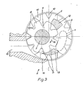
- Fig. 3 eine Prinzipdarstellung der Förderpumpe in vergrößertem Maßstab,
- Fig. 4 eine Draufsicht auf die Frontplatte des Steuereinschubes,
- Fign. 5 u. 6 Seitenansichten des Steuereinschubes,
- Fign. 7 u. 8 zwei Blockschaltbilder der elektrischen Steuerung und
- Fig. 9 eine Darstellung des Betriebsspannungsverlaufs für die Servomotoren.
- 1 shows the machine in front view and partly in the vertical direction,
- 2 is a side view of the machine, also partially cut in the vertical direction,
- 3 is a schematic diagram of the feed pump on an enlarged scale,
- 4 is a plan view of the front panel of the control module,
- Fig. 5 u. 6 side views of the control module,
- Fig. 7 u. 8 two block diagrams of the electrical control and
- Fig. 9 shows the operating voltage curve for the servo motors.
Das in Portionen abzufüllende teigige Medium, insbesondere Wurstbrät, wird vorzugsweise mittels einer geeigneten, nicht dargestellten Beschickungseinrichtung in den Füllbehälter 1 eingebracht. Er hat zweckmäßigerweise eine konische Gestalt und befindet sich über einer Füllpumpe 2. Genauer gesagt ist es so, daß der Auslaß 3 des Füllbehälters 1 über dem Einlaß 4 der Füllpumpe 2 liegt. Wesentliche Elemente der Füllpumpe sind ein innenverzahntes, antreibbares Außenrad 5 mit Antriebswelle 7 und ein hierzu exzentrisch angeordnetes, außenverzahntes Ritzel 6 mit Lagerzapfen 7. Die Ritzelzähne 8 greifen in die Zahnlücken 9 des Außenrads 5, während die Zähne 1O des Außenrads 5 in die Zahnlücken 11 des Ritzels 6 eintreten.The doughy medium to be filled in portions, in particular sausage meat, is preferably introduced into the filling
Das in die Pumpe eingebrachte Medium füllt den Teil des Pumpeninnern vollständig aus, der durch die beiden Druckstücke od. Druckstückteile 12 und 13 sowie die momentan im Bereich dieser Druckstücke befindlichen Zahnlücken definiert ist. Nach unten ist dieser Raum durch einen scheibenförmigen Boden des Außenrads 5, auf welchem die Zähne senkrecht zur Bildebene (Fig. 3) stehen, begrenzt, während die obere Begrenzung durch einen in Fig. 3 abgenommenen Deckel erreicht wird. Wenn man das Außenrad 5 im Sinne des Pfeils 14 antreibt, so nimmt es das Ritzel 6 in gleicher Drehrichtung mit. Über die Zahnlücken 11 und 9 wird das Medium zum Auslaß 15 der Pumpe transportiert. Dort treten dann die Zähne wechselweise in die Zahnlücken ein und bewirken dadurch das Entleeren der Zahnlücken in den Auslaß 15 und eine vorgeschaltete Tasche 16 des Gehäuses.The medium introduced into the pump completely fills the part of the pump interior which is defined by the two pressure pieces or
An den Auslaß 15 der Füllumpe 2 schließt sich ein Füllrohr 17 an. Darauf befindet sich eine geraffte Wursthülle 18. Sie durchsetzt einen Spaltraum zwischen dem freien Füllrohrende und einem sogenannten Bremsring 19. Das in Ablaufrichtung 2O vordere Ende der Hülle 18 ist in geeigneter Weise verschlossen, beispielsweise durch einen Knoten. Wenn man nun in diese, wie gesagt vorne verschlossene Wursthülle das Wurstbrät od. dgl. hineinpumpt, so füllt sie sich. Sie wird dabei sukzessive vom Füllrohr abgezogen und entrafft. Dieser ablaufende gefüllte Wurststrang 21 wird in nachstehend noch näher erläuterter Weise in vorgegebenen Abständen eingeschnürt, um dadurch Würste insbesondere gleicher Länge zu bilden.A filling
Die Füllpumpe 2 wird mit Hilfe eines elektrisch steuerbaren Motors 22, insbesondere eines Magnetläufers, intermittierend angetrieben. Der Motor ist mit Hilfe eines Mikroprozessors, einer elektrischen Steuereinrichtung 23, steuerbar. Die Linie 24 symbolisiert die elektrische Verbindung der Steuereinrichtung 23 mit dem Motor 22. Bei langsam ablaufendem Vorgang steht der ablaufende gefüllte Wurststrang 21 still, während sich das Füllrohr 17 mit der Wursthülle 18 und dem Bremsring 19 wenigstens einmal um ihre Längsachse drehen. Weil jedoch diese Vorgänge außerordentlich schnell ablaufen, beispielsweise 3OO bis 4OO mal pro Minute, kommt es in Wirklichkeit lediglich zu einem Abbremsen und Beschleunigen des Motors 22 und der Abdreheinrichtung 25, die mit Hilfe eines zweiten, elektrisch steuerbaren Motors (26) in der nachstehend beschriebenen Weise antreibbar ist. Auch dieser zweite Motor 26 ist über den Mikroprozessor bzw. die elektrische Steuereinrichtung 23 antreib- und steuerbar. Dies symbolisiert die Linie 27 in Fig. 2. Beim Motor 26 handelt es sich gleichfalls um einen Servomotor bzw. einen Magnetläufer. Die beiden Motore 22 und 26 werden also wechselweise ein- und ausgeschaltet, wobei man sich ihre Betriebsweise bei schnellem Arbeiten, also bei hoher Wurstzahl pro Zeiteinheit mittels einer Sinuskurve und einer überlagerten Cosinuskurve bildlich leicht vorstellen kann (vgl. auch Fig. 8).The filling
Der steuerbare Motor bzw. dessen Abtriebswelle 28 ist mittels wenigstens eines Getriebes 29 - beim Ausführungsbeispiel indirekt - mit der Pumpenantriebswelle 37 antriebsmäßig verbunden. Beim Getriebe 29 handelt es sich vorzugsweise um ein Zahnriemengetriebe mit dem auf die Abtriebswelle 28 aufgesetzten Antriebsrad 3O und dem getriebenen Rad 31 sowie dem Zahnriemen 32. Das getriebene Rad 31 sitzt auf einer Getriebewelle 33, die ein Ritzel 34 des Getriebes 35 trägt. Es kämmt mit einem Zahnrad 36 auf der Pumpenantriebswelle 37.The controllable motor or its
Die Getriebewelle 33 ist über das Getriebegehäuse nach außen geführt und die Getriebewellenverlängerung 38 trägt ein Antriebsrad 39 eines weiteren Getriebes 4O, welches gleichfalls als Riemen- oder Zahnriemengetriebe ausgebildet sein kann. Der Riemen 41 dieses Getriebes 4O treibt ein Ritzel oder Rad 42 an, welches auf einer Antriebswelle eines Impulsgebers 43 befestigt ist. Auch dieser Impulsgeber ist mit der elektrischen Steuereinrichtung 23 verbunden, was in Fig. 1 schematisch mit der Linie 44 zum Ausdruck kommt. Er liefert die notwendigen Impulse, welche zum Steuern der Antriebe der Maschine und verschiedener Funktionen, z.B. Portionieren, des Prozessors erforderlich sind.The
Vorzugsweise über eine lösbare Kupplung 45 ist die Getriebewellen-Verlängerung 38 mit einer Antriebswelle 46 für ein Förderelement 47 antriebsverbunden. Dieses ist Teil einer Fördervorrichtung, welche das Medium im Füllbehälter 1 zwangsweise zum Pumpeneinlaß 4 fördert. Die Antriebswelle 46 trägt zu diesem Zwecke an ihrem in Fig. 1 oberen Ende ein Ritzel 48, dessen Zähne mit denjenigen eines Zahnkranzes 49 kämmen. Der Zahnkranz ist drehfest mit dem Förderlement 47 verbunden, welches ihn in Achsrichtung durchsetzt. Das Förderelement hat die Gestalt einer Förderschnecke und es ist aus bandförmigem Material hergestellt. Letzteres wurde zu einer kegelförmigen Spirale gebogen, wie Fig. 1 der Zeichnung deutlich zeigt und welche an die Kontur des Behälters angepaßt ist.The
Die Abdreheinrichtung 25 ist vorzugsweise abnehmbar. Sie besitzt eine Vorgelegewelle 5O, welche gemäß Fig. 2 vom zweiten Motor 26 intermittierend angetrieben wird. Ein erstes Ritzel 51 der Vorgelegewelle 5O treibt, vorzugsweise wiederum mittels eines Riemens 52, ein Zahnrad 53 an, welches drehfest mit dem Füllrohr 17 verbunden oder einstückig damit hergestellt ist. Der Riemen 52 kann ebenfalls ein Zahnriemen sein, genauso wie der Riemen 54, welcher die Drehverbindung zwischen einem zweiten Ritzel 55 od. dgl. und einem zweiten Zahnrad 56 od. dgl. schafft. Letzteres ist an einen Halter für den Bremsring angeformt oder damit verbunden. Die beiden Übersetzungen 51, 53 sowie 55, 56 sind gleich, um ein synchrones Drehen des Füllrohrs 17 und des Bremsrings 19 einschließlich der gerafften Wursthülle 18 zu gewährleisten.The twist-
Die elektrische Steuereinrichtung 23, die der Abfüllmaschine eine sehr hohe Flexibilität hinsichtlich der Art der Abfüllartikel und eine besonders hohe Abfüllgeschwindigkeit verleiht, kann auch als Steuereinschub 63 ausgebildet sein, der eine Bedienungskonsole 57 mit einer Anzeige 59 und einem Tastenfeld 6O sowie Anschlüssen 61 für eine Stichprobenwaage und 62 für einen Protokollierdrucker enthält. Ferner verfügt der Steuereinschub 63 über Steckplätze zur Aufnahme einer Prozessorkarte 66, einer Ein-/Ausgabekarte 67 und eines Netzteiles 68, wie die Fign. 4 und 5 erkennen lassen.The
Fig. 6 zeigt außerdem eine Anordnung von Steckern 69 für den Anschluß der Anzeige 59, 7O, für den Anschluß des Tastenfeldes 6O sowie 71 für den Anschluß eines Druckers und einer Waage. Die zum Schutz des elektrischen Teiles vorgesehenen Sicherungen sind bei 72 dargestellt.Fig. 6 also shows an arrangement of
Die elektrische Steuereinrichtung 23, deren wesentliches Element eine zentrale Steuereinheit (CPU) ist, erzeugt die für die Bedienung, Einstellung und den Betrieb erforderlichen elektrischen Steuersignale. Standardfunktionen, die hierbei gesteuert werden, sind Portionieren, Abdrehen, Bedienungspausen sowie eine Korrektur der Dosierung für die erste Portion. Außerdem kann die Füllgeschwindigkeit über die Betriebsspannung des ersten und zweiten Servomotors 22 und 26 eingestellt werden. Die Betriebsspannung der Servomotore hat einen rampenartigen Verlauf im Bereich von O bis 1O Volt maximal, wobei der Wert 1O Volt der maximalen Füllgeschwindigkeit (1OO %) entspricht. Die rampenförmige Betriebsspannung, kurz Steuerrampe genannt, kann in ihrer Form, bzw. ihrem Verlauf, der Konsistenz des Füllgutes und der Beschaffenheit des Verpackungsmaterials angepaßt werden, wobei die günstigsten Werte empirisch ermittelt und anschließend in einem Lese-/Schreibspeicher abgelegt werden.The
Die elektrische Steuereinrichtung 23 verfügt, wie zuvor bereits erwähnt wurde, über einen Lese-/Schreibspeicher 77, in dem die Portionsparameter, wie Gewicht, Pause, Abdrehen, Abdrehverzögerung, Füllgeschwindigkeit usw. für 1OO verschiedenartige Portionen gespeichert werden können. Der Lese-/Schreibspeicher 77 wird über eine Notstromversorgung 83, einen Akkumulator, der sich auf der Prozessorplatine befindet, versorgt, so daß auch bei ausgeschaltetem Gerät oder bei herausgezogener Prozessorkarte die Portionsdaten erhalten bleiben. Über das Tastenfeld 6O mit insgesamt 16 Tasten können neue Portionen eingegeben oder geändert werden. Nach dem Einschalten der Maschine erscheint in der 2O-stelligen alphanumerrischen Anzeige eine Informationszeile, die Portionsnummer, Name und Gewicht der Portionen anzeigt. Durch Eingabe der Portionsnummer können die gewünschte Portion und deren Daten abgerufen werden.The
Durch Betätigung der Funktionstaste D von den insgesamt vier vorgesehenen Funktionstasten A bis D, auf die noch eingegangen werden wird, kommen nacheinander sämtliche Portionsparameter zur Anzeige und können eingegeben, geändert oder über die Pluszeichen- oder Minuszeichen-Tasten während des Laufes der Füllmaschine geändert werden.By pressing the function key D from the four provided function keys A to D, which will be discussed later, all portion parameters are displayed one after the other and can be entered, changed or changed using the plus sign or minus sign buttons while the filling machine is running.
Wie bereits früher schon erwähnt wurde, sind in der Frontplatte 64 des Steuereinschubs 63 (Fig. 4) zwei Schnittstellenbuchsen 61 und 62 für V 24 bzw. RS 232 Schnittstellen eingelassen, welche den Anschluß einer Stichprobenwaage und eines Druckers ermöglichen. Abweichungen der Stichproben vom Sollwert werden zu einem Korrekturwert verarbeitet, der im Portionierparameter "Korrektur" angezeigt und abgespeichert wird.As already mentioned earlier, two
Die Stichproben werden vom Drucker protokolliert. Bei Betätigung der Funktionstaste C oder beim Start einer neuen Portion wird eine Auswertung der statistischen Daten der Stichproben ausgedruckt (Sollwert, Anzahl, Mittelwert, Standardabweichung, Minimum und Maximum). Beim Start der Stichproben und Auswertung werden Datum und Uhrzeit ausgedruckt, welche von einer Uhr 82 geliefert werden, die über den Prozessorbus 75 an die CPU 73 angeschlossen ist.The samples are logged by the printer. When the function key C is pressed or when a new portion is started, an evaluation of the statistical data of the samples is printed out (setpoint, number, mean, standard deviation, minimum and maximum). When starting the sampling and evaluation, the date and time are printed out, which are supplied by a
Zur Sicherung der eingegebenen Portionsdaten können diese nach Anschluß eines externen Speichers, vorzugsweise eines Kassettenrekorders, auf ein Speichermedium, im Falle eines Kassettenrekorders auf eine Kassette abgespeichert werden.To secure the entered portion data, these can be stored on a storage medium after connecting an external memory, preferably a cassette recorder, in the case of a cassette recorder on a cassette.
Die Bestriebsspannung der Servomotore mit einstellbarer Beschleunigungs- und Bremsrampe sowie die programmierbare Füllgeschwindigkeit steuert sowohl den Einfüll- als auch den Abdrehvorgang, welch letzterer durch das Abdrehsignal AD (vgl. Fig. 7) eingeleitet wird.The operating voltage of the servo motors with adjustable acceleration and braking ramp as well as the programmable filling speed controls both the filling and the calibration process, the latter of which is initiated by the calibration signal AD (see FIG. 7).
Die Eingabe der Betriebsparameter erfolgt in zwei Ebenen, in der a) Füllebene und b) Systemebene, die beide im folgenden aufgelistet werden:The operating parameters are entered on two levels, a) filling level and b) system level, both of which are listed below:
- O Portion = Eingabe der PortionsnummerO Portion = Enter the portion number
-
1 Korrektur = Eingabe Korrekturwert
Optimierung durch +/- -Taste
Wiegekorrektur über Korrekturwaage wirkt auf Korrekturwert1 correction = input of correction value
Optimization with the +/- key
Weighing correction using a correction balance affects the correction value -
2 Nachlauf = keine Eingabe
Messung des Maschinenauslaufs2 Follow-up = no entry
Measurement of the machine outlet - 3 1. Portion = Veränderung der 1. Portion -5O bis +15O Gramm3 1st serving = change of 1st serving -5O to + 15O grams
-
4 Pause = Eingabe begrenzt auf 5 sec. = max.
Wert Abdrehverzögerung = min. Optimierung durch +/- -Taste
Auflösung Millisekunden4 pause = input limited to 5 sec. = Max.
Calibration delay value = min. Optimization with the +/- key
Resolution milliseconds -
5 Abdrehen = Eingabe O - O,6 sec.
Optimierung durch +/- -Taste
Auflösung Millisekunden5 Turn off = input O - O, 6 sec.
Optimization with the +/- key
Resolution milliseconds -
6 Abdrehverzögerung = Eingabe O bis O,15O Sek. eingestellte Pause begrenzt
Abdrehverzögerung
Optimierung durch +/- -Taste
Auflösung Millisekunden6 Turn-off delay = input O to O, the pause set for 15O seconds is limited
Turn off delay
Optimization with the +/- key
Resolution milliseconds -
7 Füllgeschwindigkeit = Eingabe in %
Optimierung durch +/- -Taste
Auflösung O,4 %7 Filling speed = entry in%
Optimization with the +/- key
Resolution O, 4% - 8 Gewichtseingabe = Eingabe O - 3O OOO Gramm8 Weight input = input O - 30 OOO grams
-
9 Portionen pro Strang = Eingabe 1 bis 9 für Wiegekorrektur
Anzahl der Portionen, die zusammen gewogen werden.
Sollgewicht = Portionen/Strang × Portionsgewicht9 servings per line =input 1 to 9 for weighing correction
Number of servings that are weighed together.
Target weight = portions / strand × portion weight -
1O Name = Namenseingabe für Portion über +/- -Taste Position des Zeichens.
O - 9 Zeichendurchlauf mit programmierbarer Schleife betätigte Ziffer = Schleifenmultiplikator1O Name = name input for portion via +/- key position of the character.
O - 9 character scroll with programmable loop actuated digit = loop multiplier -
11 mit/ohne Clipper = Ein- oder Ausschalten der Selbsthaltung des Startsignals bis Portionsende
Anzeige ja/nein
Umschaltung durch Betätigung einer Zifferntaste11 with / without clipper = switching on or off the self-holding of the start signal until the end of the portion
Display yes / no
Switching by pressing a number key -
12 Ebenenwechsel = Wahl Füllebene - Systemebene;
Umschaltung durch Betätigung einer Zifferntaste12 level change = choice filling level - system level;
Switching by pressing a number key
- 13 Uhreinstellung = Anzeige und Einstellung des Uhrenbausteins13 Clock setting = display and setting of the clock module
- 14 Speichern auf Kassette = Portionsspeichern auf Kassette abspeichern über FSK-Modem14 Save on cassette = save portion storage on cassette via FSK modem
- 15 Laden von Kassette = von Kassette auf Portionsspeicher laden über FSK-Modem15 Loading from cassette = loading from cassette to portion storage via FSK modem
-
16 Schnittstellen = Einstellung der Schnittstellenparameter
Baudrate,Übertragungsformate16 interfaces = setting of the interface parameters
Baud rate, transmission formats
Die eingegebenen Parameter werden von der elektrischen Steuereinrichtung entsprechend verarbeitet und führen zur Erzeugung der entsprechenden Ausgangsrampe, einschließlich eines Portionierungssignals P, des Abdrehsignals AD und eines Geschwindigkeitskorrektursignals V, das immer dann erzeugt wird, wenn die Geschwindigkeit, gemessen über den Impulsgeber 43, zu hoch ist. Der Impulsgeber ist für einen weiten Bereich von Anwendungen und Betriebszuständen dimensioniert und im vorliegenden Beispiel mit einem Gramm je Impuls bewertet.The input parameters are processed accordingly by the electrical control device and lead to the generation of the corresponding output ramp, including a portioning signal P, the calibration signal AD and a speed correction signal V, which is generated whenever the speed, measured via the
Für die Steuerung bedeutet dies, daß beispielsweise bei der Herstellung von 25O g-Würsten 25O Impulse pro Wurst erzeugt werden. Arbeitet die Füllmaschine mit einer Geschwindigkeit von 1OO Würsten pro Minute, so entspricht dieses einer Impulsrate von 25 OOO Impulsen pro Minute bzw. von 416 2/3 Impulsen pro Sekunde, was einer Impulsfrequenz von 416,666 Hz entspricht.For the control this means that, for example, during the production of 250 g sausages, 250 pulses per sausage are generated. If the filling machine works at a speed of 100 sausages per minute, this corresponds to a pulse rate of 25,000 pulses per minute or 416 2/3 pulses per second, which corresponds to a pulse frequency of 416.666 Hz.
Wie der obigen Tabelle unter a) 5, 6 und 7 zu entnehmen ist, ist das Abdrehen bzw. Clipsen in bestimmten Grenzen einstellbar, damit die gewünschten Betriebsparameter optimal erreicht werden. Dies gilt auch für die Korrektur der ersten Portion, die aus folgenden Gründen erforderlich ist:As can be seen in the above table under a) 5, 6 and 7, the twisting or clipping can be set within certain limits so that the desired operating parameters are optimally achieved. This also applies to the correction of the first portion, which is necessary for the following reasons:
Wenn die Maschine anläuft, also der allererste Teil der Verpakkungshülle mit dem teigigen Medium gefüllt wird, muß auch zunächst die Pumpe gefüllt werden und erst wenn diese ganz gefüllt ist und auch das teigige Medium bis zum vorderen Ende der gerafften Verpackungshülle vorgedrungen ist, wird durch eine Art Rückstau ein kontinuierlicher Pumpendruck erreicht. Während der Bildung oder Füllung der ersten Portion arbeitet die Pumpe zunächst mit ansteigendem, d.h. nicht konstantem Druck. Dies bedeutet, daß bei Vorgabe einer gewissen Impulszahl für das Gewicht der Portion eine zu leichte erste Portion, beispielsweise eine zu kurze erste Wurst, erzeugt wird. Würde man nun für die im vorhergehenden Beispiel gewählte 25O g-Wurst 25O Impulse zugrundelegen, so wöge sie vermutlich nur 22O g, weil ihr vorderes Ende mit gewissermaßen zu geringem Druck gefüllt wurde. Ein empirischer Korrekturwert kann dann der elektrischen Steuereinrichtung 23 mitgeteilt und dort gespeichert werden, so daß jeweils die erste Portion verschiedener Portionsnummern auch später jederzeit mit korrektem Gewicht herstellbar ist.When the machine starts up, i.e. the very first part of the packaging envelope is filled with the doughy medium, the pump must first be filled and only when it is completely filled and the doughy medium has penetrated to the front end of the shirred packaging, a kind of back pressure creates a continuous pump pressure. During the formation or filling of the first portion, the pump initially works with increasing, ie not constant, pressure. This means that if a certain number of pulses is given for the weight of the portion, a portion that is too light, for example a portion of the first sausage that is too short, is generated. If one were to base the 25O g sausage selected in the previous example on 25O impulses, then it would probably only weigh 22O g because its front end was filled with pressure that was too low, so to speak. An empirical correction value can then be communicated to the
Fig. 7 zeigt nun die wesentlichen Komponenten der elektrischen Steuereinrichtung 23, bestehend aus einer zentralen Steuereinheit (CPU) 73, beispielsweise einem Mikroprozessor bekannter Bauart, dessen Betriebsabläufe in zeitlicher Hinsicht von einem Taktgeber 74 gesteuert werden. Die zentrale Steuereinheit 73 ist über einen Prozessorbus 75, der die erforderlichen Steuer-, Adressen- und Datenleitungen umfaßt, mit einem Lese-/Schreibspeicher 77, einem Lesespeicher 78 und einem programmierbaren Ein-/Ausgabeadapter verbunden. Der letztgenannte Adapter ist über einen Ein-/Ausgabebus 76 mit einer Ein-/Ausgabesteuerung 8O sowie einem Timer 81 und dem Tastenfeld 6O verbunden. Die Anzeige wiederum ist über die Ein-/Ausgabesteuerung 8O an den Mikrocomputer angeschlossen. Die für Protokollierzwecke vorgesehene Uhr, die Zeit und Datum angibt, ist über den bereits erwähnten Prozessorbus 75 angeschlossen.7 now shows the essential components of the
Bei dem in Fig. 7 dargestellten Mikrocomputer fällt der Ein-/Ausgabesteuerung 8O die besondere Aufgabe zu, externe Steuersignale, wie beispielsweise die Impulse des Impulsgebers 43, über die Leitungen 44, das Startsignal ST oder beispielsweise die Daten der Stichprobenwaage über den Anschluß 61 dem Mikrocomputer zuzuführen bzw. Steuersignale aus dem Computer den übrigen elektrischen Komponenten zuzuführen, wie beispielsweise die Ausgangsrampe RAMP1 für den ersten Servomotor 22 und RAMP2 für den zweiten Servomotor 26 oder die auszudruckenden Daten über den Anschluß 62 dem Drucker zuzuführen.In the microcomputer shown in Fig. 7, the input / output control 8O has the special task of external control signals, such as the pulses from the
Andere Signale, wie beispielsweise das Abdrehsignal AD oder das Portioniersignal P oder das Geschwindigkeitssignal V, das eine zu hohe Geschwindigkeit signalisiert, werden für eine prozessorinterne Verarbeitung benötigt. Das Wechselspiel von Portioniersignal P und Abdrehsignal AD ist in Fig. 8 dargestellt, die im übrigen die gegenphasigen Ausgangsrampen RAMP1 und RAMP2 zeigt.Other signals, such as the calibration signal AD or the portioning signal P or the speed signal V, which signals a speed that is too high, are required for processing within the processor. The interplay between portioning signal P and calibration signal AD is shown in FIG. 8, which otherwise shows the opposite-phase output ramps RAMP1 and RAMP2.
Die endgültige Form der Ausgangsrampen wird weitgehend durch das verwendete Material und die Arbeitsgeschwindigkeit, d.h. die Pro duktionsgeschwindigkeit der Portionen bestimmt und weitgehend empirisch ermittelt. Diese Werte sind speicherbar, wobei als Speicher hierfür sowohl der Lese-/Schreibspeicher 77 als auch der Lesespeicher 78, der das eigentliche Steuerprogramm enthält, in Betracht kommen.The final shape of the exit ramps is largely determined by the material used and the working speed, ie the pro dosing speed of the portions determined and largely determined empirically. These values can be stored, both the read /
Die folgende Schaltungsbeschreibung bezieht sich auf das Blockschaltbild gemäß Fig. 8.The following circuit description relates to the block diagram according to FIG. 8.
- 1. MPU = Mikroprozessor 68O91. MPU = microprocessor 68O9
-
2. Speicherblock
- a) Programmspeicher
EPROM 4 × 2732 A 16 KByte - b) Rezeptspeicher - Akku gepuffert
RAM 2 × 6116 4 KByte
- a) Program memory
EPROM 4 × 2732 A 16 KB - b) Recipe memory - battery buffered
RAM 2 × 6116 4 KB
- a) Programmspeicher
-
3. I-O-Block
- A) ACIA = ASYNCHRONOUS COMMUNICATIONS INTERFACE ADAPTER 685O
ACIA 1 = asynchrone Schnittstellen für Waage und FSK Modem
ACIA 2 = asynchrone Schnittstelle für Drucker - B) PIA = PERIPHERAL INTERFACE ADAPTER 6821
Ein- und Ausgänge für Maschinenansteuerung,
Tastenfeldabfrage,
programmierbare Baudrateneinstellung
zu schnelle Füllgeschwindigkeit
Spannungsüberwachung - C) PTM = PROGRAMMABLE TIMER 684O
Eingang Impulse - Drehimpulsgeber
Portionszähler
Zeitglied mit Zeitbasis 1 ms
- A) ACIA = ASYNCHRONOUS COMMUNICATIONS INTERFACE ADAPTER 685O
ACIA 1 = asynchronous interfaces for scale and FSK modem
ACIA 2 = asynchronous interface for printers - B) PIA =
PERIPHERAL INTERFACE ADAPTER 6821
Inputs and outputs for machine control,
Keypad query,
programmable baud rate setting
filling speed too fast
Voltage monitoring - C) PTM = PROGRAMMABLE TIMER 684O
Impulse input - rotary encoder
Portion counter
Timing element with a time base of 1 ms
- A) ACIA = ASYNCHRONOUS COMMUNICATIONS INTERFACE ADAPTER 685O
-
4. Adresscodierung
- 8 - Bit - Dekoder 74LS138 - 8 Adressblöcke
- O = IOSEL = I-O-Block (ACIA, PIA, PTM)
- 1 = PS = Platinenselektion Anzeige und D/A-Wandler
- 2 = UHR = Uhrenselektion
- 3 = RAM = RAM-Selektion
- 4 = EPROM 1
- 5 = EPROM 2
- 6 = EPROM 3 = EPROM-Selektion
- 7 = EPROM 4
- 8-bit decoder 74LS138 - 8 address blocks
- O = IOSEL = IO block (ACIA, PIA, PTM)
- 1 = PS = board selection display and D / A converter
- 2 = CLOCK = clock selection
- 3 = RAM = RAM selection
- 4 =
EPROM 1 - 5 =
EPROM 2 - 6 =
EPROM 3 = EPROM selection - 7 =
EPROM 4
-
5. Programmierbare Baudratenerzeugung
12 Bit - Binärzahler 4O4O
2 × 8 BIT-Mulitplexer 74LS1525. Programmable baud rate generation
12 bit binary counter 4O4O
2 × 8 BIT multiplexers 74LS152 -
6. Spannungsüberwachung
Ladespannung an + 5 V Versorgung6. Voltage monitoring
Charging voltage at + 5 V supply -
7. Uhrenbaustein Akku gepuffert
Ausgabe von Datum und Uhrzeit für statistische Dokumentation7. Clock module battery buffered
Output of date and time for statistical documentation
-
1. V 24 (RS 232 C) - 4 Draht-Schnittstellen galvanische Entkopplung durch Optokoppler
mit RS 232 C - Treiber 1488 L
und RS 232 C - Receiver 1489 L
für Waagen und Druckeranschluß1. V 24 (RS 232 C) - 4 wire interfaces galvanic decoupling through optocouplers
with RS 232 C driver 1488 L
and RS 232 C receiver 1489 L
for scales and printer connection - 2. FSK-Modem für Kassettenrekorderanschluß um Rezeptspeicherinhalt auf Kassette zu sichern.2. FSK modem for cassette recorder connection to save recipe memory content on cassette.
-
3. Maschinenanschluß
- A) Transistorausgänge für Portion und Abdrehen zur Ansteuerung von Magnetventilen galvanische Entkopplung durch Optokoppler
- B) Eingänge für Start und Impulse mit RC-Gliedern zur Entstörung und galvanischer Entkopplung durch Optokoppler
- C) Analogausgang
- a) Ansteuerung für Drehstromservoantrieb mit Steuerrampe O - 1O V mit analoger galvanischer Entkopplung
- b) Ansteuerung der Hubverstelleinrichtung (programmierbare Geschwindigkeitseinstellung) für pneumatisch/hydraulischen Antrieb O - 5 V mit analoger galvanischer Entkopplung
- A) Transistor outputs for portioning and twisting to control solenoid valves galvanic decoupling through optocouplers
- B) Inputs for start and impulses with RC elements for interference suppression and galvanic decoupling through optocouplers
- C) Analog output
- a) Control for three-phase servo drive with control ramp O - 1O V with analog galvanic decoupling
- b) Control of the stroke adjustment device (programmable speed setting) for pneumatic / hydraulic drive O - 5 V with analog galvanic decoupling
-
4. Anzeigenansteuerung
über Datenbus und Adressbustreibern4. Display control
via data bus and address bus drivers - 5. Digital/Analogwandler mit Datenbusspeicher für programmierbare Geschwindigkeitseinstellung5. Digital / analog converter with data bus memory for programmable speed setting
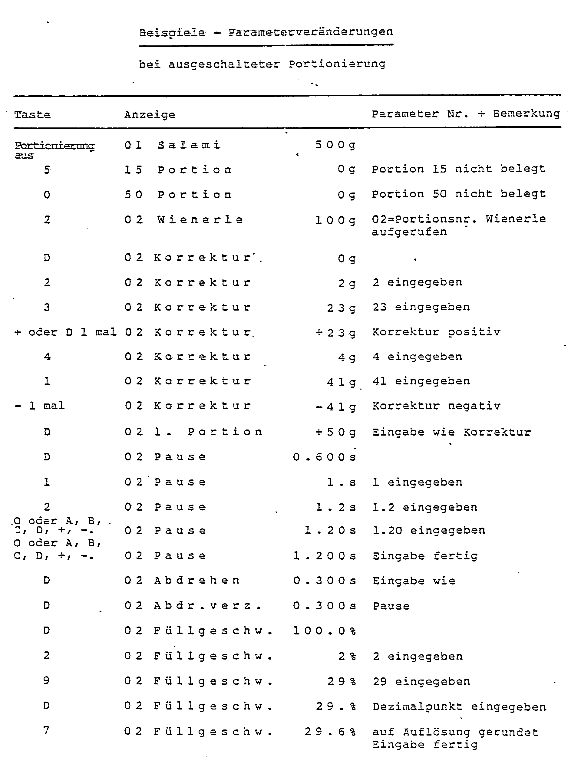
Als Anlagen 1 bis 3 werden Beispiele überreicht und zwar:
Anlage 1 Beispiel einer eingestellten Portion,Anlage 2 Beispiel einer Parameterveränderung bei laufender Portionierung,- Beispiel 3 Parameterveränderungen bei ausgeschalteter Portionierung.


-
Appendix 1 Example of a set portion, -
Appendix 2 Example of a parameter change during portioning, - Example 3 Parameter changes when portioning is switched off.
Claims (18)
Priority Applications (1)
| Application Number | Priority Date | Filing Date | Title |
|---|---|---|---|
| AT87105298T ATE72504T1 (en) | 1986-05-24 | 1987-04-10 | MACHINE FOR FILLING DOUGH MEDIA, ESPECIALLY SAUSAGE BRAEET. |
Applications Claiming Priority (2)
| Application Number | Priority Date | Filing Date | Title |
|---|---|---|---|
| DE3617560A DE3617560C2 (en) | 1986-05-24 | 1986-05-24 | Machine for filling doughy media, in particular sausage meat |
| DE3617560 | 1986-05-24 |
Publications (4)
| Publication Number | Publication Date |
|---|---|
| EP0250733A2 true EP0250733A2 (en) | 1988-01-07 |
| EP0250733A3 EP0250733A3 (en) | 1989-04-12 |
| EP0250733B1 EP0250733B1 (en) | 1992-02-12 |
| EP0250733B2 EP0250733B2 (en) | 1995-01-25 |
Family
ID=6301602
Family Applications (1)
| Application Number | Title | Priority Date | Filing Date |
|---|---|---|---|
| EP87105298A Expired - Lifetime EP0250733B2 (en) | 1986-05-24 | 1987-04-10 | Machine for stuffing doughy products, especially sausages |
Country Status (10)
| Country | Link |
|---|---|
| US (1) | US4823439A (en) |
| EP (1) | EP0250733B2 (en) |
| JP (1) | JPS6333206A (en) |
| AT (1) | ATE72504T1 (en) |
| CA (1) | CA1265382A (en) |
| DE (1) | DE3617560C2 (en) |
| DK (1) | DK260587A (en) |
| ES (1) | ES2030009T5 (en) |
| FI (1) | FI87129C (en) |
| NO (1) | NO169934C (en) |
Cited By (4)
| Publication number | Priority date | Publication date | Assignee | Title |
|---|---|---|---|---|
| EP0395177A2 (en) * | 1989-04-28 | 1990-10-31 | HITEC Co., Ltd. | Apparatus for manufacturing sausages or the like |
| WO1998017119A1 (en) * | 1996-10-21 | 1998-04-30 | Townsend Engineering Company | Method and means for linking sausage |
| EP2407038A1 (en) | 2010-07-15 | 2012-01-18 | Albert Handtmann Maschinenfabrik GmbH & Co. KG | Method and device for cooling food machines |
| DE102016216851A1 (en) * | 2016-09-06 | 2018-03-08 | Albert Handtmann Maschinenfabrik Gmbh & Co. Kg | Method and filling machine for filling a food |
Families Citing this family (15)
| Publication number | Priority date | Publication date | Assignee | Title |
|---|---|---|---|---|
| IT1223796B (en) * | 1988-09-02 | 1990-09-29 | Cselt Centro Studi Lab Telecom | COAXIAL WAVER GUIDE CHANGER |
| JPH0675464B2 (en) * | 1989-08-04 | 1994-09-28 | プリマハム株式会社 | Sausage filling device |
| IT220303Z2 (en) * | 1990-11-23 | 1993-09-16 | Righele Giovanni | DRIVE DEVICE FOR HOPPER OF A ROTARY BAGGING PUMP FOR GROUND MEAT. |
| ES2131474B1 (en) * | 1997-08-29 | 2000-03-01 | Castro Alejandro Ruiz | CONTROL DEVICE FOR A DRIVE SYSTEM FOR SAUSAGE TIE MACHINES. |
| DE29808373U1 (en) * | 1998-05-08 | 1999-09-16 | Vemag Maschinen & Anlagenbau Gmbh | Filling machine for sausage meat or the like. with a foldable storage container |
| DE19824829A1 (en) * | 1998-06-04 | 1999-12-23 | Vemag Maschinen & Anlagenbau Gmbh | Production of uniform length sausage links from natural animal gut casings |
| JP2000332503A (en) | 1999-05-25 | 2000-11-30 | Sharp Corp | Circularly polarized wave generator |
| JP3706522B2 (en) | 2000-02-25 | 2005-10-12 | シャープ株式会社 | Waveguide device for satellite receiving converter |
| EP1479297A1 (en) * | 2003-05-19 | 2004-11-24 | Borgo & C. S.A.S. Antonio | Feeding hopper for stuffing machines for soft pasties and stuffing machine for soft pasties |
| DE102008033800A1 (en) | 2008-07-18 | 2010-01-28 | Poly-Clip System Gmbh & Co. Kg | Packaging device and method for controlling a packaging device |
| CN102342308A (en) * | 2011-09-20 | 2012-02-08 | 闫树林 | Fixed-cylinder dough mixer braking device |
| JP6232625B2 (en) | 2013-04-26 | 2017-11-22 | ハイテック株式会社 | Filling equipment |
| NL2012455B1 (en) * | 2014-03-17 | 2016-01-08 | Marel Townsend Further Proc Bv | Method for preparing a casing material used in a co-extruding process of a food product, viscous gelling agent and a method and a system for preparing food products. |
| CN114711275B (en) * | 2022-04-11 | 2022-12-06 | 重庆市计量质量检测研究院 | Integration sausage filling equipment |
| EP4275503A1 (en) * | 2022-05-11 | 2023-11-15 | Poly-clip System GmbH & Co. KG | Off-power grid clipping machine for producing sausage-shaped products |
Citations (2)
| Publication number | Priority date | Publication date | Assignee | Title |
|---|---|---|---|---|
| EP0096378A1 (en) * | 1982-06-02 | 1983-12-21 | Teepak Produktie N.V. | Method and apparatus for automatically making strands of sausages |
| EP0114084A2 (en) * | 1983-01-18 | 1984-07-25 | 3 EFFE S.N.C. di L. Russo & C. | System of reversing the sequential position of the operative units in automatic packaging machinery |
Family Cites Families (8)
| Publication number | Priority date | Publication date | Assignee | Title |
|---|---|---|---|---|
| DE1532010C3 (en) * | 1966-06-30 | 1980-06-26 | Karl Schnell, Maschinenfabrik, 7065 Winterbach | Conveyor device for shredded material with a feed pump and a vacuum suction system |
| CH540647A (en) * | 1971-04-29 | 1973-08-31 | Handtmann Metallguss Albert | Device for portioning a pasty mass in a tubular casing |
| CH583521A5 (en) * | 1974-01-22 | 1977-01-14 | Handtmann Albert Fa | |
| DE3018793A1 (en) * | 1980-05-16 | 1981-11-26 | Albert Handtmann Gmbh & Co, 7950 Biberach | ARRANGEMENT FOR THE FOLLOWING PORTIONING OF A FLOWABLE FILLING MEASUREMENT, IN PARTICULAR SAUSAGE MEASUREMENT |
| DE3311567A1 (en) * | 1983-03-30 | 1984-10-04 | Karl 7065 Winterbach Schnell | MACHINE FOR FILLING DOUGH MEDIA, ESPECIALLY SAUSAGE BREAD |
| AT381209B (en) * | 1984-10-29 | 1986-09-10 | Nordischer Maschinenbau | CONTINUOUSLY WORKING DEVICE FOR FOLLOWING APPLICATION OF PORTIONS OF A PASTOUS MASS |
| DE3544448A1 (en) * | 1985-12-16 | 1987-06-19 | Handtmann Albert Maschf | METHOD AND DEVICE FOR FILLING OUT AIR-CONTAINING, DEFORMABLE MEASURES |
| US4709450A (en) * | 1987-01-13 | 1987-12-01 | Teepak, Inc. | Apparatus and methods of stuffing food casings to provide dimensionally uniform products |
-
1986
- 1986-05-24 DE DE3617560A patent/DE3617560C2/en not_active Expired - Fee Related
-
1987
- 1987-04-10 AT AT87105298T patent/ATE72504T1/en not_active IP Right Cessation
- 1987-04-10 EP EP87105298A patent/EP0250733B2/en not_active Expired - Lifetime
- 1987-04-10 ES ES87105298T patent/ES2030009T5/en not_active Expired - Lifetime
- 1987-05-22 NO NO872162A patent/NO169934C/en not_active IP Right Cessation
- 1987-05-22 CA CA000537715A patent/CA1265382A/en not_active Expired - Fee Related
- 1987-05-22 DK DK260587A patent/DK260587A/en not_active Application Discontinuation
- 1987-05-22 US US07/054,268 patent/US4823439A/en not_active Expired - Lifetime
- 1987-05-22 FI FI872284A patent/FI87129C/en not_active IP Right Cessation
- 1987-05-25 JP JP62126081A patent/JPS6333206A/en active Pending
Patent Citations (2)
| Publication number | Priority date | Publication date | Assignee | Title |
|---|---|---|---|---|
| EP0096378A1 (en) * | 1982-06-02 | 1983-12-21 | Teepak Produktie N.V. | Method and apparatus for automatically making strands of sausages |
| EP0114084A2 (en) * | 1983-01-18 | 1984-07-25 | 3 EFFE S.N.C. di L. Russo & C. | System of reversing the sequential position of the operative units in automatic packaging machinery |
Cited By (8)
| Publication number | Priority date | Publication date | Assignee | Title |
|---|---|---|---|---|
| EP0395177A2 (en) * | 1989-04-28 | 1990-10-31 | HITEC Co., Ltd. | Apparatus for manufacturing sausages or the like |
| EP0395177A3 (en) * | 1989-04-28 | 1992-02-26 | HITEC Co., Ltd. | Apparatus for manufacturing sausages or the like |
| WO1998017119A1 (en) * | 1996-10-21 | 1998-04-30 | Townsend Engineering Company | Method and means for linking sausage |
| AU721788B2 (en) * | 1996-10-21 | 2000-07-13 | Townsend Engineering Company | Sausage encasing machines |
| EP2407038A1 (en) | 2010-07-15 | 2012-01-18 | Albert Handtmann Maschinenfabrik GmbH & Co. KG | Method and device for cooling food machines |
| DE102010031393A1 (en) | 2010-07-15 | 2012-01-19 | Albert Handtmann Maschinenfabrik Gmbh & Co. Kg | Apparatus and method for cooling food processing machines |
| DE102010031393B4 (en) * | 2010-07-15 | 2012-07-05 | Albert Handtmann Maschinenfabrik Gmbh & Co. Kg | Apparatus and method for cooling food processing machines |
| DE102016216851A1 (en) * | 2016-09-06 | 2018-03-08 | Albert Handtmann Maschinenfabrik Gmbh & Co. Kg | Method and filling machine for filling a food |
Also Published As
| Publication number | Publication date |
|---|---|
| ES2030009T3 (en) | 1992-10-16 |
| JPS6333206A (en) | 1988-02-12 |
| DE3617560A1 (en) | 1987-11-26 |
| DE3617560C2 (en) | 1996-08-14 |
| ES2030009T5 (en) | 1995-08-16 |
| NO872162L (en) | 1987-11-25 |
| NO169934C (en) | 1992-08-26 |
| US4823439A (en) | 1989-04-25 |
| EP0250733B1 (en) | 1992-02-12 |
| EP0250733B2 (en) | 1995-01-25 |
| EP0250733A3 (en) | 1989-04-12 |
| NO169934B (en) | 1992-05-18 |
| FI87129C (en) | 1992-12-10 |
| DK260587A (en) | 1987-11-25 |
| FI872284A0 (en) | 1987-05-22 |
| NO872162D0 (en) | 1987-05-22 |
| FI87129B (en) | 1992-08-31 |
| CA1265382A (en) | 1990-02-06 |
| ATE72504T1 (en) | 1992-02-15 |
| DK260587D0 (en) | 1987-05-22 |
| FI872284A (en) | 1987-11-25 |
Similar Documents
| Publication | Publication Date | Title |
|---|---|---|
| EP0250733B1 (en) | Machine for stuffing doughy products, especially sausages | |
| EP0392083A1 (en) | Method of, and device for, dividing a string of sausages produced by a stuffing machine into single sausages | |
| EP0476258B1 (en) | Method and device for manufacturing sausages | |
| DE2921427C2 (en) | Device for intermittently ejecting a sausage mass or the like | |
| EP1902622A1 (en) | Device and method for dividing a filled sausage strand | |
| DE2744350A1 (en) | HANGING DEVICE FOR PORTIONED SAUSAGE CHAINS | |
| DE4021305C2 (en) | Device for continuously conching chocolate mass | |
| EP0013552B1 (en) | Method and apparatus for portioning a pasty mass, particularly sausage stock | |
| DE69817374T2 (en) | MEAT EMULSION PUMP CONTROL SYSTEM FOR MEAT FILLING MACHINE AND METHOD FOR USE THEREOF | |
| DE2402817A1 (en) | Prodn. of sausages with the same weight, length and dia. - using constant filling rate related to sausage sepn. into desired portions | |
| DE1904589C3 (en) | Control circuit for a plant for the continuous production of polyurethane foam | |
| EP1082543B1 (en) | Regulation of the stroke frequency of a dosing pump | |
| DE19726238C1 (en) | Method and device for filling sausage casings | |
| EP1199940B1 (en) | Nozzle arrangement, nozzle holder and device for extruding materials in dough form | |
| EP0621095A1 (en) | Method for the intermittent straightening of wire | |
| EP0246667B1 (en) | Process and apparatus for preparing stuffed products | |
| EP1582098B1 (en) | Device and method for twisting extruded sausage strand | |
| EP1205110A1 (en) | Length measuring unit with a clipping machine | |
| EP1312264B1 (en) | Length measuring unit with clipping machine | |
| AT381209B (en) | CONTINUOUSLY WORKING DEVICE FOR FOLLOWING APPLICATION OF PORTIONS OF A PASTOUS MASS | |
| DE19601720A1 (en) | Operating sealing equipment for sausage meat in casings | |
| EP1607000B1 (en) | Method and device for producing sausage | |
| DE3537580C1 (en) | Apparatus for smoking cigarettes | |
| DE4335612C1 (en) | Method for controlling the drive of a mixing appliance and mixing appliance for carrying out the method. | |
| DE1172406B (en) | Portioning machine |
Legal Events
| Date | Code | Title | Description |
|---|---|---|---|
| PUAI | Public reference made under article 153(3) epc to a published international application that has entered the european phase |
Free format text: ORIGINAL CODE: 0009012 |
|
| AK | Designated contracting states |
Kind code of ref document: A2 Designated state(s): AT BE CH ES FR GB IT LI NL SE |
|
| PUAL | Search report despatched |
Free format text: ORIGINAL CODE: 0009013 |
|
| AK | Designated contracting states |
Kind code of ref document: A3 Designated state(s): AT BE CH ES FR GB IT LI NL SE |
|
| 17P | Request for examination filed |
Effective date: 19890928 |
|
| 17Q | First examination report despatched |
Effective date: 19910104 |
|
| ITF | It: translation for a ep patent filed |
Owner name: DE DOMINICIS & MAYER S.R.L. |
|
| GRAA | (expected) grant |
Free format text: ORIGINAL CODE: 0009210 |
|
| AK | Designated contracting states |
Kind code of ref document: B1 Designated state(s): AT BE CH ES FR GB IT LI NL SE |
|
| REF | Corresponds to: |
Ref document number: 72504 Country of ref document: AT Date of ref document: 19920215 Kind code of ref document: T |
|
| GBT | Gb: translation of ep patent filed (gb section 77(6)(a)/1977) | ||
| ET | Fr: translation filed | ||
| PLBI | Opposition filed |
Free format text: ORIGINAL CODE: 0009260 |
|
| PLBI | Opposition filed |
Free format text: ORIGINAL CODE: 0009260 |
|
| 26 | Opposition filed |
Opponent name: HOEGGER ALPINA AG Effective date: 19921110 |
|
| 26 | Opposition filed |
Opponent name: VEMAG MASCHINENBAU GMBH Effective date: 19921112 Opponent name: HOEGGER ALPINA AG Effective date: 19921110 |
|
| NLR1 | Nl: opposition has been filed with the epo |
Opponent name: VEMAG MASCHINEBAU GMBH. Opponent name: HOEGGER ALPINA AG |
|
| PUAH | Patent maintained in amended form |
Free format text: ORIGINAL CODE: 0009272 |
|
| STAA | Information on the status of an ep patent application or granted ep patent |
Free format text: STATUS: PATENT MAINTAINED AS AMENDED |
|
| 27A | Patent maintained in amended form |
Effective date: 19950125 |
|
| AK | Designated contracting states |
Kind code of ref document: B2 Designated state(s): AT BE CH ES FR GB IT LI NL SE |
|
| EAL | Se: european patent in force in sweden |
Ref document number: 87105298.1 |
|
| REG | Reference to a national code |
Ref country code: CH Ref legal event code: AEN |
|
| NLR2 | Nl: decision of opposition | ||
| ET3 | Fr: translation filed ** decision concerning opposition | ||
| GBTA | Gb: translation of amended ep patent filed (gb section 77(6)(b)/1977) |
Effective date: 19950322 |
|
| ITF | It: translation for a ep patent filed |
Owner name: DE DOMINICIS & MAYER S.R.L. |
|
| NLR3 | Nl: receipt of modified translations in the netherlands language after an opposition procedure | ||
| REG | Reference to a national code |
Ref country code: ES Ref legal event code: DC2A Kind code of ref document: T5 Effective date: 19950816 |
|
| REG | Reference to a national code |
Ref country code: GB Ref legal event code: IF02 |
|
| PGFP | Annual fee paid to national office [announced via postgrant information from national office to epo] |
Ref country code: GB Payment date: 20020412 Year of fee payment: 16 |
|
| PGFP | Annual fee paid to national office [announced via postgrant information from national office to epo] |
Ref country code: CH Payment date: 20020415 Year of fee payment: 16 |
|
| PGFP | Annual fee paid to national office [announced via postgrant information from national office to epo] |
Ref country code: SE Payment date: 20020422 Year of fee payment: 16 |
|
| PGFP | Annual fee paid to national office [announced via postgrant information from national office to epo] |
Ref country code: NL Payment date: 20020430 Year of fee payment: 16 |
|
| PGFP | Annual fee paid to national office [announced via postgrant information from national office to epo] |
Ref country code: BE Payment date: 20020508 Year of fee payment: 16 |
|
| PGFP | Annual fee paid to national office [announced via postgrant information from national office to epo] |
Ref country code: ES Payment date: 20020516 Year of fee payment: 16 |
|
| PGFP | Annual fee paid to national office [announced via postgrant information from national office to epo] |
Ref country code: FR Payment date: 20030311 Year of fee payment: 17 |
|
| PGFP | Annual fee paid to national office [announced via postgrant information from national office to epo] |
Ref country code: AT Payment date: 20030313 Year of fee payment: 17 |
|
| PG25 | Lapsed in a contracting state [announced via postgrant information from national office to epo] |
Ref country code: GB Free format text: LAPSE BECAUSE OF NON-PAYMENT OF DUE FEES Effective date: 20030410 |
|
| PG25 | Lapsed in a contracting state [announced via postgrant information from national office to epo] |
Ref country code: SE Free format text: LAPSE BECAUSE OF NON-PAYMENT OF DUE FEES Effective date: 20030411 |
|
| PG25 | Lapsed in a contracting state [announced via postgrant information from national office to epo] |
Ref country code: LI Free format text: LAPSE BECAUSE OF NON-PAYMENT OF DUE FEES Effective date: 20030430 Ref country code: CH Free format text: LAPSE BECAUSE OF NON-PAYMENT OF DUE FEES Effective date: 20030430 Ref country code: BE Free format text: LAPSE BECAUSE OF NON-PAYMENT OF DUE FEES Effective date: 20030430 |
|
| BERE | Be: lapsed |
Owner name: KARL *SCHNELL MASCHINENFABRIK Effective date: 20030430 |
|
| PG25 | Lapsed in a contracting state [announced via postgrant information from national office to epo] |
Ref country code: NL Free format text: LAPSE BECAUSE OF NON-PAYMENT OF DUE FEES Effective date: 20031101 |
|
| NLV4 | Nl: lapsed or anulled due to non-payment of the annual fee |
Effective date: 20031101 |
|
| EUG | Se: european patent has lapsed | ||
| GBPC | Gb: european patent ceased through non-payment of renewal fee |
Effective date: 20030410 |
|
| REG | Reference to a national code |
Ref country code: CH Ref legal event code: PL |
|
| PG25 | Lapsed in a contracting state [announced via postgrant information from national office to epo] |
Ref country code: AT Free format text: LAPSE BECAUSE OF NON-PAYMENT OF DUE FEES Effective date: 20040410 |
|
| PG25 | Lapsed in a contracting state [announced via postgrant information from national office to epo] |
Ref country code: ES Free format text: LAPSE BECAUSE OF NON-PAYMENT OF DUE FEES Effective date: 20040412 |
|
| PG25 | Lapsed in a contracting state [announced via postgrant information from national office to epo] |
Ref country code: FR Free format text: LAPSE BECAUSE OF NON-PAYMENT OF DUE FEES Effective date: 20041231 |
|
| REG | Reference to a national code |
Ref country code: FR Ref legal event code: ST |
|
| PG25 | Lapsed in a contracting state [announced via postgrant information from national office to epo] |
Ref country code: IT Free format text: LAPSE BECAUSE OF NON-PAYMENT OF DUE FEES;WARNING: LAPSES OF ITALIAN PATENTS WITH EFFECTIVE DATE BEFORE 2007 MAY HAVE OCCURRED AT ANY TIME BEFORE 2007. THE CORRECT EFFECTIVE DATE MAY BE DIFFERENT FROM THE ONE RECORDED. Effective date: 20050410 |
|
| REG | Reference to a national code |
Ref country code: ES Ref legal event code: FD2A Effective date: 20040412 |