JP6232625B2 - Filling equipment - Google Patents
Filling equipment Download PDFInfo
- Publication number
- JP6232625B2 JP6232625B2 JP2013094170A JP2013094170A JP6232625B2 JP 6232625 B2 JP6232625 B2 JP 6232625B2 JP 2013094170 A JP2013094170 A JP 2013094170A JP 2013094170 A JP2013094170 A JP 2013094170A JP 6232625 B2 JP6232625 B2 JP 6232625B2
- Authority
- JP
- Japan
- Prior art keywords
- raw material
- filling
- filling nozzle
- pump
- material supply
- Prior art date
- Legal status (The legal status is an assumption and is not a legal conclusion. Google has not performed a legal analysis and makes no representation as to the accuracy of the status listed.)
- Active
Links
- 239000002994 raw material Substances 0.000 claims description 163
- 238000012546 transfer Methods 0.000 claims description 3
- 238000007599 discharging Methods 0.000 claims description 2
- 230000007246 mechanism Effects 0.000 description 15
- 238000003860 storage Methods 0.000 description 11
- 235000013372 meat Nutrition 0.000 description 9
- 235000013580 sausages Nutrition 0.000 description 9
- 230000005540 biological transmission Effects 0.000 description 6
- 238000003825 pressing Methods 0.000 description 6
- 238000004804 winding Methods 0.000 description 6
- 238000004140 cleaning Methods 0.000 description 4
- 239000000463 material Substances 0.000 description 4
- 230000009471 action Effects 0.000 description 3
- 238000004891 communication Methods 0.000 description 3
- 230000004913 activation Effects 0.000 description 2
- 230000006870 function Effects 0.000 description 2
- 238000009434 installation Methods 0.000 description 2
- 210000000936 intestine Anatomy 0.000 description 2
- 230000002093 peripheral effect Effects 0.000 description 2
- 102000008186 Collagen Human genes 0.000 description 1
- 108010035532 Collagen Proteins 0.000 description 1
- 241001465754 Metazoa Species 0.000 description 1
- 241001494479 Pecora Species 0.000 description 1
- 230000004075 alteration Effects 0.000 description 1
- 238000013459 approach Methods 0.000 description 1
- 229920002678 cellulose Polymers 0.000 description 1
- 239000001913 cellulose Substances 0.000 description 1
- 229920001436 collagen Polymers 0.000 description 1
- 238000013461 design Methods 0.000 description 1
- 238000001514 detection method Methods 0.000 description 1
- 230000006866 deterioration Effects 0.000 description 1
- 230000000968 intestinal effect Effects 0.000 description 1
- 238000004519 manufacturing process Methods 0.000 description 1
- 238000012545 processing Methods 0.000 description 1
- 230000009467 reduction Effects 0.000 description 1
- 239000002699 waste material Substances 0.000 description 1
Images


Classifications
-
- A—HUMAN NECESSITIES
- A22—BUTCHERING; MEAT TREATMENT; PROCESSING POULTRY OR FISH
- A22C—PROCESSING MEAT, POULTRY, OR FISH
- A22C11/00—Sausage making ; Apparatus for handling or conveying sausage products during manufacture
- A22C11/02—Sausage filling or stuffing machines
- A22C11/0209—Stuffing horn assembly
-
- A—HUMAN NECESSITIES
- A22—BUTCHERING; MEAT TREATMENT; PROCESSING POULTRY OR FISH
- A22C—PROCESSING MEAT, POULTRY, OR FISH
- A22C11/00—Sausage making ; Apparatus for handling or conveying sausage products during manufacture
- A22C11/02—Sausage filling or stuffing machines
Landscapes
- Life Sciences & Earth Sciences (AREA)
- Engineering & Computer Science (AREA)
- Wood Science & Technology (AREA)
- Zoology (AREA)
- Food Science & Technology (AREA)
- Processing Of Meat And Fish (AREA)
Description
本願発明は、ソーセージ等を製造する充填装置に関する。 The present invention relates to a filling device for producing sausages and the like.
ソーセージ製品は、充填物である肉等の原料をセルロースケーシング・コラーゲンケーシング等の人工ケーシングや、羊腸、豚腸等の動物の腸のケーシング内に自動で充填したり、或いは手動で充填したりして製造されている。 Sausage products are automatically filled with raw materials such as meat, which are filled in artificial casings such as cellulose casing and collagen casing, and intestinal casings of animals such as sheep and pig intestines, or manually. Manufactured.
図13(正面図)及び図14(平面図)に従来の充填装置を示す。充填装置1は、箱状で略矩形状の本体ケース2と、本体ケース2と別体で同じく箱状で略矩形状のポンプケース10を有し、本体ケース2には、充填物である肉等の原料を空のケーシング(図示しない)に充填する充填ノズル4と、充填ノズル4に空のケーシングを自動装着するケーシング供給装置5と、充填ノズル4を回転する充填ノズル回転手段6と、空のケーシングの外周に係合し、空のケーシングを充填ノズル4の外周面方向に押圧する制動機構7と、原料が充填された充填ケーシングを前方(充填ノズル4と反対側)に送り狭窄する搬送装置であるピンチャー装置8と、充填ノズル4に原料を計量・供給する計量ポンプ9等が配置される。
FIG. 13 (front view) and FIG. 14 (plan view) show a conventional filling device. The filling device 1 has a box-like and substantially rectangular
前記ポンプケース10には、原料が上方から投入される円錐状のホッパー11と、ホッパー11内に原料を投入するためのリフトアーム12と、ホッパー11の下方に設けられる図示しないポンプ室及びベーンを有する原料供給ポンプ13(ホッパー11の底部の下方にあり、破線で示す。)と、原料供給ポンプ13を駆動するポンプ駆動モーター14等が取付けられる。
The
そして、原料供給ポンプ13と計量ポンプ9との間を原料供給管15で連結し、原料供給ポンプ13から所定量の原料を連続して計量ポンプ9を介して充填ノズル4に送り、ケーシング供給装置5によって充填ノズル4の外周に装着した収縮した空のケーシングを充填ノズル4及び制動機構7とともに回転させつつ、充填ノズル4内の原料を前方に引き出され伸ばされる空のケーシング内に充填し、原料が充填された充填ケーシングをピンチャー装置8により狭窄するとともに、その狭窄部に充填ノズル4及び制動機構7との回動により捻りを形成して、所定長さのソーセージ製品等を製造する。
The raw
上記したように従来の充填装置1は、充填ノズル4、ケーシング供給装置5、充填ノズル回転手段6、制動機構7、ピンチャー装置8及び計量ポンプ9等が本体ケース2に設けられ、ホッパー11、原料供給ポンプ13及びポンプ駆動モーター14等が本体ケース2とは別体のポンプケース10に設けられ、原料供給ポンプ13と計量ポンプ9との間を長さの長い原料供給管15で連結する構造である。そして、本体ケース2の横にポンプケース10を置いた場合、本体ケース2の一端部からリフトアーム12の先端までの長さは3590mmになる。本体ケース2とポンプケース10を別体にするものとして特許文献1及び特許文献2のものがある。
As described above, the conventional filling device 1 includes the filling nozzle 4, the casing supply device 5, the filling nozzle rotating means 6, the
ところで、本体ケース2とポンプケース10とを別体で設けるということは、別途、ポンプケース10が必要になり、その分製品コストが高騰するとともに、ポンプケース10を設置するための余分のスペースが必要になる。
By the way, providing the
また、原料供給ポンプ13と計量ポンプ9とを連結する原料供給管15の長さが長くなるので原料供給途中で原料の肉質が変質したり、原料供給管15内の送肉圧力低下による原料送肉量の減少が生じたり、充填作業の終了後に原料供給管15内に残る原料量が多くなり、その分原料が無駄になる。
In addition, since the length of the raw
また、充填装置1が据え付けられる作業場の床面は傾斜や凹凸があるので、本体ケース2に取付けられた計量ポンプ9とポンプケース10に取付けられた原料供給ポンプ13との間に床面からの高低差が生じやすく、高低差があると、原料供給管15を計量ポンプ9と原料供給ポンプ13に連結しにくくなり、毎日の充填装置1洗浄時の原料供給管15の取外し・取付け作業に時間を要することになる。
Further, since the floor surface of the work place where the filling device 1 is installed is inclined or uneven, the floor surface between the
また、原料供給管15は取り外して洗浄する必要があるが、原料供給管15の長さが長いとそれだけ重くなり取り外し及び洗浄後の組付けが困難になり、洗浄も時間を要し手間がかかることになる。
The raw
また、原料供給ポンプ13を駆動するための各種のスイッチ16a及び表示器16bを有する表示装置16は、本体ケース2と離れた位置に配置されるポンプケース10に設けられるため、作業者Sはその位置まで移動してスイッチ16aを押したり表示器16bを確認することになり、それだけ作業者Sの手間が増え且つ操作性が悪くなる。なお、本体ケース2には本体ケース2に設けられる各装置に関した各種のスイッチ17a及び表示器17bを有する表示装置17が設けられる。
Moreover, since the
また、ポンプケース10には、原料供給ポンプ13のポンプ室を低圧にして原料の流れを良好にする真空ポンプ18と、真空ポンプ18でポンプ室を低圧にする際、空気とともに吸引される原料の一部を捕捉するためのトラップ19とが設けられており、このトラップ19で捕捉される原料を作業者Sが取り除く必要がある。しかし、そのトラップ19は本体ケース2と離れた位置に配置されるポンプケース10に設けられているため、作業者Sはその位置まで移動してトラップ19から捕捉された原料を取り出すことになり、やはりそれだけ作業者Sの手間が増え且つ操作性が悪くなる。
Further, the
また、従来の自動充填用の充填装置は、自動充填専用のものであって手動充填について考慮されていないため、手動充填を行う場合、別途専用のものを用意する必要があり、するとその分生産コストが高騰する。 In addition, since the conventional automatic filling device is dedicated to automatic filling and does not consider manual filling, it is necessary to prepare a separate dedicated one when manual filling is performed. Cost increases.
本願発明の目的は、上記従来の問題を改善すること、即ち、原料供給ポンプ、ポンプ駆動モーター及びホッパー等を充填ノズル等を有する本体ケースに設ける等することにより、小型且つ安価で利便性の高い充填装置を提供することである。 The object of the present invention is to improve the above-mentioned conventional problems, that is, by providing a raw material supply pump, a pump drive motor, a hopper, etc. in a main body case having a filling nozzle, etc. It is to provide a filling device.
本願発明の特徴とするところは、以下の点にある。 The features of the present invention are as follows.
請求項1に係る発明は、本体ケースと、原料を吐出する吐出口を有する充填ノズルと、前記原料を前記充填ノズルに供給する原料供給ポンプと、ポンプ駆動モーターと、前記原料が充填された充填ケーシングを前記吐出口から吐出される前記原料の吐出方向に搬送する搬送装置と、を有する充填装置であって、前記原料供給ポンプの上方には、上方から原料が投入されるホッパーを有し、前記原料供給ポンプ、前記ポンプ駆動モーター及び前記ホッパーは、前記充填ノズルと前記搬送装置が設けられた前記本体ケースに設けられ、前記本体ケースは、一つの箱状のもので、前記充填ノズル及び前記搬送装置は、前記本体ケースの上部に設けられており、前記ホッパーは、平面視で前記充填ノズルと重なり、前記搬送装置と重ならなく、前記原料供給ポンプから送られる原料は、原料供給管を介して前記充填ノズルに送られて自動充填される構成を特徴とする。
The invention according to claim 1 is a main body case, a filling nozzle having a discharge port for discharging a raw material, a raw material supply pump for supplying the raw material to the filling nozzle, a pump drive motor, and a filling filled with the raw material. A conveying device that conveys the casing in the discharge direction of the raw material discharged from the discharge port, and has a hopper into which the raw material is charged from above above the raw material supply pump, The raw material supply pump, the pump drive motor, and the hopper are provided in the main body case provided with the filling nozzle and the transfer device, and the main body case is a single box-shaped one, and the filling nozzle and the hopper conveying apparatus, the provided on the upper portion of the main body case, the hopper overlaps with the filling nozzle in a plan view, not to overlap the conveyance device, the original Raw material fed from the feed pump is fed to the filling nozzle through the material supply pipe and said configuration is automatically filled.
請求項2に係る発明は、請求項1の構成に加え、前記ホッパーは、円錐状または多角錐状で、前記ホッパーの底部材には前記原料供給ポンプのポンプ室に連通する下部開口を有し、前記下部開口は、平面視で前記本体ケースの上面に位置する構成を特徴とする。なお、平面視は上方から見るとの意味である。 According to a second aspect of the present invention, in addition to the configuration of the first aspect, the hopper has a conical shape or a polygonal pyramid shape, and a bottom member of the hopper has a lower opening communicating with the pump chamber of the raw material supply pump. The lower opening is configured to be positioned on the upper surface of the main body case in a plan view. In addition, the plan view means that it is viewed from above.
請求項3に係る発明は、請求項1、2の構成に加え、前記充填ノズルは、前記充填ノズルを移動可能な充填ノズル用エアシリンダーのシリンダーロッドと接続部材を介して接続され、充填時には前記搬送装置に近い充填位置に位置し、非充填時には前記搬送装置から離れた初期位置に位置しており、前記充填ノズルの前記初期位置では前記接続部材は、平面視で前記ポッパーの大径端の領域内に位置する構成を特徴とする。 The invention according to claim 3, in addition to the configuration of claim 1, wherein the filling nozzle, which is connected to filling nozzle through the cylinder rod and the connecting member of the air cylinder for the movable filling nozzle, said at the time of filling located in the filling position close to the conveying device, at the time of unfilled located in the initial position away from said transport device, wherein the connecting member in the initial position of the filling nozzle, the large-diameter end of the in plan view popper It is characterized by a configuration located in the region.
請求項4に係る発明は、請求項1〜3の構成に加え、前記原料供給ポンプのポンプ室を低圧にするための真空ポンプと、前記ポンプ室及び前記真空ポンプを連結する連結管上に設けられ、吸引される前記原料を捕捉するトラップとを有し、前記トラップは、前記本体ケースの作業者側の側面に設けられる構成を特徴とする。 According to a fourth aspect of the present invention, in addition to the configurations of the first to third aspects, a vacuum pump for lowering a pump chamber of the raw material supply pump, and a connecting pipe connecting the pump chamber and the vacuum pump are provided. And a trap for trapping the raw material to be sucked, wherein the trap is provided on a side surface on the operator side of the main body case.
請求項5に係る発明は、請求項1〜4の構成に加え、前記原料供給管は、前記原料供給ポンプの原料送出口に着脱自在であり、手動充填時、前記原料供給管を取り外し、前記原料送出口に手動用充填ノズルを取り付けて手動充填する構成を特徴とする。 According to a fifth aspect of the present invention, in addition to the configurations of the first to fourth aspects, the raw material supply pipe is detachable from a raw material delivery port of the raw material supply pump, and during manual filling, the raw material supply pipe is detached, It is characterized in that a manual filling nozzle is attached to the raw material delivery port for manual filling.
請求項6に係る発明は、請求項5の構成に加え、前記充填ノズルと前記手動用充填ノズルとは、平面視平行である構成を特徴とする。 The invention according to claim 6 is characterized in that, in addition to the configuration of claim 5, the filling nozzle and the manual filling nozzle are parallel in plan view.
請求項7に係る発明は、請求項5、6の構成に加え、前記充填ノズルを用いる自動充填時と前記手動充填ノズルを用いる手動充填時での作業者の作業位置は、前記本体ケースを挟んで反対側である構成を特徴とする。 According to a seventh aspect of the invention, in addition to the configurations of the fifth and sixth aspects, the work position of the operator during the automatic filling using the filling nozzle and the manual filling using the manual filling nozzle sandwiches the main body case. It is characterized by the configuration on the opposite side.
請求項8に係る発明は、請求項1〜7の構成に加え、運転状態を表示する表示装置を有し、前記表示装置は前記本体ケース上で回動自在である構成を特徴とする。 The invention according to an eighth aspect is characterized in that, in addition to the configurations of the first to seventh aspects, a display device that displays an operating state is provided, and the display device is rotatable on the main body case.
本願発明は、原料供給ポンプ、ポンプ駆動モーター及びホッパーを充填ノズルと搬送装置とが設けられる本体ケースに一体に組み込む、より詳細には、ホッパーの底部のポンプ室に連通する下部開口を平面視で本体ケースの上面に位置させることにより、従来の本体ケースの大型化及び製品コストの高騰を抑えるとともに、設置スペースを低減することができる。 The present invention incorporates a raw material supply pump, a pump drive motor, and a hopper into a body case provided with a filling nozzle and a transfer device, and more specifically, a lower opening communicating with the pump chamber at the bottom of the hopper in a plan view. By positioning it on the upper surface of the main body case, it is possible to suppress an increase in the size of the conventional main body case and an increase in product cost, and to reduce an installation space.
また、トラップを本体ケースの作業者側の側面に設けることにより、作業者がトラップから原料を取り出す作業を容易にすることができる。 Further, by providing the trap on the side surface on the operator side of the main body case, the operator can easily take out the raw material from the trap.
また、スイッチを有する表示装置を回動自在にすることにより、原料供給ポンプ等の作業操作を容易にすることができる。 Further, by making the display device having a switch turnable, the operation of the raw material supply pump and the like can be facilitated.
また、本体ケース上で自動充填とともに手動充填を可能にするハイブリッド式にすることにより、充填装置の機能及び価値を高めることができるとともに、利便性を向上することができる。 In addition, by using a hybrid system that allows automatic filling and manual filling on the main body case, the function and value of the filling device can be enhanced, and convenience can be improved.
また、上記ハイブリッド式のもののそれぞれの作業者の操作位置を本体ケースを挟んだ反対側にすることにより、手動充填時に用いる作業台の設置及び手動充填時の作業を容易にすることができる。 In addition, by setting the operation position of each operator of the hybrid type to the opposite side across the main body case, it is possible to facilitate the installation of the work table used during manual filling and the work during manual filling.
また、充填ノズルと手動用充填ノズルとを平面視平行にすることにより、本体ケースの奥行き方向の長さの増加を抑えることができる。 Further, by making the filling nozzle and the manual filling nozzle parallel to each other in plan view, an increase in the length of the main body case in the depth direction can be suppressed.
以下、図を参照して本願発明の実施例について説明する。なお、図2においてシリンダー収納箱32側を後方側とし、ピンチャー装置60側を前方側とし、シリンダー収納箱32からピンチャー装置60にかけての方向を前後方向(本体ケースの長辺方向であって、紙面の左右方向)とし、その前後方向に直交する方向を奥行き方向(本体ケースの短辺方向であって、紙面の上下方向)とし、その手前を手前側(作業者Sがいる側)とし、その奥を奥側(作業者Sと反対側)とする。
Embodiments of the present invention will be described below with reference to the drawings. 2, the
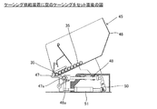
充填装置20は、箱状の本体ケース21を有する。本体ケース21はその底部に脚22及びストッパ23を有する移動可能なもので、本体ケース21の上面24(以下、単に上面24という。)は略矩形状で、後方側から前方側に向かってシリンダー収納箱32、充填ノズル30、充填ノズル回転装置40、ケーシング供給装置45、制動機構55及び搬送装置であるピンチャー装置60が配置され、原料を自動充填する。
The
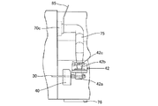
また、充填ノズル30の奥側の上面24上には原料投入口であるホッパー71が配置され、更に、ホッパー71の下方には原料供給ポンプ70が配置される。
Further, a
本体ケース21内には、制御箱25、駆動モーター26、ピンチャー用駆動モーター27、ポンプ駆動モーター28及び真空ポンプ29が配置される。
A
前記制御箱25は、その内部に演算処理装置及びメモリ等を有する制御装置を有し、原料供給ポンプ70、充填ノズル30、制動機構55及びピンチャー装置60等の駆動機構を制御する。
The
前記駆動モーター26は、両端に駆動軸26a、26bを有し、それぞれの駆動軸26a、26bはプーリ及びベルトを介して充填ノズル回転装置40及び制動機構55に連結し、設定される所定回転数で充填ノズル30及び制動機構55を回動する。
The
前記ピンチャー用駆動モーター27は、同様にプーリ及びベルトを介してピンチャー装置60に連結し、設定される所定回転数でピンチャー装置60を回動する。
Similarly, the
前記ポンプ駆動モーター28は歯車を介して原料供給ポンプ70に連結し、設定される所定回転数で原料供給ポンプ70を回動する。
The
前記真空ポンプ29は、真空ポンプ29に直結される真空ポンプ駆動用モーター29aにより設定される所定回転数で回動される。
The
上面24上に設けられる各部材について説明する。前記シリンダー収納箱32は、本体ケース21の後方側に前後方向に設けられる断面矩形状の細長い箱状の部材で、内部に充填ノズル用エアシリンダー33及びケーシング押し用エアシリンダー34が配置される。
Each member provided on the
それぞれの配置位置は、充填ノズル用エアシリンダー33及びケーシング押し用エアシリンダー34ともに前後方向であって、且つ充填ノズル用エアシリンダー33が上方で、ケーシング押し用エアシリンダー34がその直下である。このような配置にすることにより本体ケース21の奥行き方向の長さを短くできる。
The arrangement positions of both the filling
また、図1に示すようにシリンダー収納箱32は、その後端部32aが本体ケース21の後方端21aより後方側に突き出ている。このような形態にすることにより、本体ケース21の前後方向の長さを短くすることができる。
Further, as shown in FIG. 1, the
前記充填ノズル30は、シリンダー収納箱32の前方側に設けられる丸パイプ状の直管部材であり、前後方向且つ水平に設けられ、その一端は接続部材であり、請求項3の接続部材に相当する回転継手31を介して前記充填ノズル用エアシリンダー33のシリンダーロッド33aに連結される。そして、充填時には充填ノズル用エアシリンダー33は回転継手31とともに充填ノズル30を前方側に押し、1本のケーシングへの充填が終わると充填ノズル用エアシリンダー33は回転継手31とともに充填ノズル30を後方側の初期位置である図1及び図2の位置に戻す。そして、充填ノズル30の初期位置では接続部材である回転継手31は、平面視でポッパーの大径端71aの領域内に位置する。
The said filling
充填ノズル30の他端には吐出口30a(図3参照)を有し、原料供給ポンプ70から押し出される原料を、充填ノズル30の外周上に装着される空の収縮ケーシング35の前方の一枚状ケーシング35aの前端部内に供給する。
The other end of the filling
前記ケーシング押し用エアシリンダー34の前方側にはケーシング押し37が連結される。ケーシング押し37は、充填ノズル30の直下で前後方向に配置される部材であり、押しロッド37a及び押し部材37bを有する(図3参照)。
A
押しロッド37aの後方端はケーシング押し用エアシリンダー34の前方端に連結し、押しロッド37aの前方端には押し部材37bが連結される。押し部材37bは、その先端に充填ノズル30の外周が挿入する嵌合穴37bbを有する。
The rear end of the
そして、ケーシング押し37は、収縮ケーシング35に原料を充填する際、収縮ケーシング35の後端部35bに当接し、ケーシング押し用エアシリンダー34の作用により収縮ケーシング35を前方側に押して1本の収縮ケーシング35の全てに原料が効率的に充填されるように補助する。
When the
ケーシング押し37の位置を検知する図示しない検出装置が用意されており、ケーシング押し37が所定距離前進すると1本の収縮ケーシング35の全てが使用されたと判断し、充填ノズル用エアシリンダー33及びケーシング押し用エアシリンダー34を駆動して充填ノズル30及びケーシング押し37を後方側に移動する。その後、ケーシング供給装置45が駆動し、後退した充填ノズル30の軸心X−X上(図3のX−X方向)に新たな収縮ケーシング35をセットする。
A detection device (not shown) for detecting the position of the
前記充填ノズル回転装置40は、シリンダー収納箱32の前方側に設けられる部材で、その内部に充填ノズル30が侵入する図示しない開孔を有している。そして、前記駆動モーター26の駆動軸26aにプーリ、ベルト及びクラッチを介して連結され、充填ノズル30が充填ノズル用エアシリンダー33により前記開孔内を前方側に充填位置まで押されるとクラッチが係合し、充填ノズル30を設定される所定の回転数で回動する。
The filling
充填ノズル回転装置40とケーシング供給装置45との間には、充填ノズル30を支持するノズル支持ケーシング42が設けられる(図10参照)。このノズル支持ケーシング42は、内部空間42aを有しており、充填ノズル30は内部空間42aを通って前後方向に貫通している。
A
また、ノズル支持ケーシング42は、奥側から手前側に開口する貫通口42bを有し、この貫通口42bには原料供給管75の一端が嵌合しクランプ42cにより固定される。そして、充填ノズル30が充填位置に移動すると、充填ノズル30の側面に設けられる図示しない開孔が内部空間42aに位置し、原料供給管75を介して送られる原料はこの開孔より充填ノズル30内に供給される。
The
なお、本発明の原料供給管75は、従来例のものに比べその長さが大幅に短縮されるため、原料供給途中で原料の肉質が変質したり、原料供給管内の送肉圧力低下による原料送肉量の減少が生じたり、充填作業の終了後に原料供給管内に残る原料量が多くなり、その分原料が無駄になる弊害が防止でき、更に、原料供給管の取り外し、組付け及び洗浄が容易になる。
In addition, since the length of the raw
即ち、原料供給管75は原料供給ポンプ70の原料送出口70cとノズル支持ケーシング42とを連結するものであり、略L字形状に曲がった形状を有している。充填装置20は原料供給ポンプ70とノズル支持ケーシング42とを共に本体ケース21に設け、両者の位置関係を一定に保つ構成を有している。そのために、充填装置20の作業場の床面に傾斜や凹凸があっても、原料送出口70cとノズル支持ケーシング42との間での高低差や奥行き方向の位置ズレが起きない。その結果、原料供給管75を原料送出口70cとノズル支持ケーシング42に容易に取付けることができ、毎日の充填装置20洗浄時の原料供給管75取外し・取付け作業が短時間で終了する。
That is, the raw
充填装置20は、下部開口72を本体ケース21の上面に位置させることによって、原料送出口70cからノズル支持ケーシング42迄の前後方向距離と、原料送出口70cから充填ノズル30迄の奥行き方向距離とが短く構成されていて、略L字形状に曲がった原料供給管75の総長さは短い。
The filling
原料供給管75の長さが短く、原料供給管75内の送肉圧力の低下が少ないので、従来公知なギャポンプ式の計量ポンプ9を設けなくても、所要量の原料をケーシングに充填できる。また、原料の変質を起こす上記計量ポンプ9を設けていないので、品質の高いソーセージを製造できる。が、本願発明は計量ポンプ9を備えた充填装置にも適用できる。さらに、原料供給管75の長さが短いので、原料供給管75内での原料の変質を低減できたり、充填作業終了後の原料供給管75内に残る原料量が少なく、原料の無駄が減少する。
Since the length of the raw
前記ケーシング供給装置45は、ノズル支持ケーシング42の前方側に設けられ、充填ノズル30の外周上に自動的に新たな収縮ケーシング35を装着可能にする。その一例を図5及び図6に示す。
The
ケーシング供給装置45は、ケーシングホッパー46、第1クランプ47、第2クランプ48、押圧片50及びクランプ用エアーシリンダー51を有する。
The
前記ケーシングホッパー46は、奥側から手前側に向かって下がるように傾斜される収納部材であり、内部には複数個の空の収縮ケーシング35が収納される。
The
前記第1クランプ47及び第2クランプ48はそれぞれV字状の頭部47a、48aを有し、それらV字状の頭部47a、48aは充填ノズル30の軸心X−Xに直交する奥行き方向(図の左右方向)に対向して配置される。そして、第1クランプ47は前記クランプ用エアーシリンダー51の手前側(図の左側)の端部に連結し、クランプ用エアーシリンダー51の奥側(図の右側)の端部は、一定の距離離れてシーソー状に揺動する押圧片50の一端に対向し、押圧片50の他端は第2クランプ48の奥側の端部に当接している。
The
充填時には、クランプ用エアーシリンダー51は図5の位置にあるが、充填中の1本の収縮ケーシング35が全て使い切られると上記したように充填ノズル30はケーシング供給装置45と充填ノズル回転装置40との間の初期位置まで軸心X−Xに沿って後退する。
At the time of filling, the clamping
その後、クランプ用エアーシリンダー51は第1クランプ47を矢印で示すように奥側に移動するとともに、押圧片50の一端を奥側に押す。すると、押圧片50の他端は第2クランプ48を矢印で示すように手前側に押す。その結果、最下方にある収縮ケーシング35は、V字状の頭部47a、48aに挟まれる図6の位置、即ち、充填ノズル30の軸心X−X上に位置することになる。図6の状態の後、図5の状態に戻る。
Thereafter, the
前記制動機構55は、一枚状ケーシング35aを充填ノズル30と共に回動する部材で、図3及び図4に示すようにプーリー57及び制動部材58を有する。
The
前記プーリー57は、回動可能で前記駆動モーター26によって駆動軸26bを介して回動される。また、プーリー57の中央下部開口内には制動部材58が挿入されプーリー57と共回りする。
The
前記制動部材58は、中央に丸い下部開口を有する筒状の部材で、その下部開口の内周面には軸方向に伸びた複数のリブ状突起58aが等間隔で放射状に伸びている。そして、複数のリブ状突起58aの下部開口の内径は充填ノズル30の外径よりも大径とされており、収縮ケーシング35は、複数のリブ状突起58aと充填ノズル30の外周との間で引き伸ばされて一枚状ケーシング35aになる。
The braking
搬送装置である前記ピンチャー装置60は、原料が充填された充填ケーシング36を狭窄して充填ノズル30の前方へ搬送するものである。ピンチャー装置60は、図4に示すように一対の巻掛伝動手段61、61を平行に配置してなるもので、それぞれの巻掛伝動手段61、61は、駆動軸62と、従動軸63(図1参照)と、駆動軸62と従動軸63との間に巻回されるチェーン64を有するとともに、チェーン64には複数個のラグ65と複数個のピンチャー部材66を有している。
The
前記ラグ65は充填ケーシング36の外周を挟み込む部材であり、前記ピンチャー部材66は、充填ケーシング36を狭窄し端部を形成するとともに、その端部に捻りを生じさせるための断面略V字状の部材である。また、ピンチャー装置60は、回転数が可変可能なピンチャー用駆動モーター27により所望回転数で運転される。
The
そして、平行に配置される一対の巻掛伝動手段61、61が回転すると、それぞれの巻掛伝動手段61、61の複数個のラグ65は、充填ケーシング36を挟み込む形態で前方側に進み、それぞれの巻掛伝動手段61、61の複数個のピンチャー部材66は、充填ケーシング36を狭窄し端部を形成する。その結果、充填ノズル30及び制動機構55の回転によりその狭窄箇所に捻り部が形成される。
And when a pair of winding transmission means 61 and 61 arranged in parallel rotate, a plurality of
尚、本実施例装置のピンチャー装置60は、充填ケーシング36を充填ノズル30の吐出口30aから吐出される原料の吐出方向に搬送する搬送装置の一例である。本願発明の搬送装置は前記ピンチャー装置60に限定されない。例えば、特許文献1に開示されたコンベア手段36のようにリンクを形成しない構成であってもよいし、特開平2−268638号公報に開示された装置のように絞り部材と搬送ベルトとが別体で設けられた構成のソーセージリンク形成装置であってもよい。
The
前記したように上面24上にはホッパー71が配置され、ホッパー71の下方には原料供給ポンプ70が配置される。
As described above, the
前記ホッパー71は、円錐状部材711及び底部材712からなる。そして、円錐状部材711は薄板状で、その上部に円形の大径端71aを有する。また、円錐状部材711の下方は円形の小径端71bと、小径端71bから外方に突き出る円形のフランジ713を有する。なお、円錐状部材711は多角錐状、例えば4角錐状であってもよい。
The
前記底部材712は、円錐状部材711のフランジ713に固定される肉厚の平面視正方形の部材であり、内部に上下に貫通する下方ほど絞られるテーパー状の連通孔714が設けられる。そして、連通孔714の下端は図7に示すようにホッパー71の中心軸より偏心する形態で原料供給ポンプ70のポンプ室70aに連通する楕円状の下部開口72とされる(図8参照)。なお、この下部開口72は請求項2の下部開口に相当する。
The
ホッパー71の底部材712は原料供給ポンプ70のポンプ上部70d(図9参照)に接触した状態で配置されており、底部材712に形成された下部開口72は原料供給ポンプ70上に位置している(図8参照)。本願発明においては、上記したこの位置関係を「下部開口は、平面視で前記本体ケースの上面に位置する(請求項2参照)」という。
The
また、底部材712の後方側の下方には、軸715が設けられており、図1及び図9に示すようにホッパー71を後方側に反時計方向に回動可能にしている。
Further, a
符号73はリフトアームであり、リフトアーム73はアーム部73a及びコ字状の載置部73bを有する。そして、コ字状の載置部73bに肉等の原料を入れたミートワゴン74を載せ、アーム部73aを図示しない油圧機構で時計方向に回動して大径端71aの上方から原料をホッパー71内に投入する。
ところで、ポンプ室70aは汚れるため洗う必要がある。そのため、ホッパー71は図9に示すように軸715を介してリフトアーム73の載置部73b側(後方側)に反時計方向に傾けることができ、ホッパー71を傾けるとポンプ室70aが露出する。そこでポンプ室70a及びベーン70bを清掃する。
By the way, the
このように、ホッパー71を本体ケース21とは反対側のリフトアーム73の載置部73b側に傾ける形態にすることにより、充填装置20の各部材に邪魔されることなく容易に傾動することができるとともに、ポンプ室70a及びベーン70bの清掃を容易にすることができる。
In this way, by tilting the
また、本体ケース21を挟んでピンチャー装置60の反対側にリフトアーム73を設け、リフトアーム73を本体ケース21方向に時計方向に回動させる形態により、本体ケース21とアーム部73aまでの前後方向の長さの増加を最小にすることができる。因みに従来のものは図14に示すように3590mmであったところ、本願発明のものは図2に示すように2565mmにすることができた。
Further, a
前記原料供給ポンプ70は、肉等の原料を充填ノズル30に供給するものであり、ホッパー71の直下に設けられ、ポンプ室70a及び複数のベーン70bを有するベーンポンプである。そして、ポンプ室70aは水平方向に拡がり、ベーン70bの軸は垂直方向で、複数のベーン70bは軸から放射方向に伸びている。
The raw
上記したように下部開口72は、ポンプ室70aに連通する。そのため、ホッパー71の原料は、下部開口72よりポンプ室70aに入り込みポンプ室70aの原料送出口70c(図2及び図10参照)より原料供給管75に送られる。なお、図2に見えない複数のベーン70bを破線で示し、下部開口72直下の見える部分は実線で示している。
As described above, the
そして、原料供給ポンプ70は、変速可能なサーボモーターである前記ポンプ駆動モーター28によって駆動され、所定の量の原料を充填ノズル30に送る。
The raw
本願発明は、原料供給ポンプ70及び原料供給ポンプ70の駆動機構等を充填ノズル30と搬送装置(ピンチャー装置60)を設けた本体ケース21に設けること、即ち一体に組む込むこと、より具体的にはホッパー71のポンプ室70aに連通する下部開口72を本体ケース21の上面24に位置させることであり、更に具体的にはその下部開口72をできるだけ前方側に位置させることにより本体ケース21を小型化することである。
In the present invention, the raw
即ち、より具体的には図2に示すように平面視で下部開口72をシリンダー収納箱32より前方側に位置させたり、平面視で下部開口72をシリンダー収納箱32より前方側で且つ充填ノズル30の奥側(図2では上方)に位置させるとよい。視点を変えると、ホッパー71の大径端71aを本体ケース21の後方端21aより前方側に位置させるとよい。
More specifically, as shown in FIG. 2, the
更に視点を変えると、充填ノズル用エアシリンダー33とケーシング押し用エアシリンダー34を、平面視でホッパー71の大径端71aと底部材712との間の領域に配置し、そして、初期位置上の充填ノズル30と充填ノズル用エアシリンダー33のシリンダーロッド33aとの接続部材である回転継手31を平面視でホッパー71の大径端71aの領域内に位置させて本体ケース21の小型化させるとよい。前記充填ノズル用エアシリンダー33とケーシング押し用エアシリンダー34とを、サーボモータで駆動される公知のリニアアクチュエータに置き換えることができる。
When the viewpoint is further changed, the filling
原料供給ポンプ70のポンプ室70aは、前記真空ポンプ29に連結管29bを介して連通されており、ポンプ室70aを低圧にして原料の流入を容易にしている。ところで、ポンプ室70aを真空ポンプ29で真空引きすると連結管29b内に原料の一部が侵入するため、その原料を捕捉するためのトラップ76が本体ケース21の側面であり作業者Sの作業位置側の側面に設けられる(図1及び図2参照)。
The
このトラップ76は、内部に真空室761を有し、この真空室761内には真空ポンプ29に連通するメッシュのフィルター76b(図11参照)を有し、その原料取出口を開閉する蓋は透明窓76a(図11参照)である。そして、このトラップ76は、図1及び図2に示すように、作業者Sの作業位置近傍の本体ケース21の側面に配置される。そのため、作業者Sは移動することなくトラップ76に原料等が捕捉されているかを確認し、捕捉されていれば透明窓76aを開けて真空室761に溜まった原料等を取り出すことができる。なお、トラップ76の下流側には安全を期して第2トラップ29cが設けられる。
The
上面24上には表示装置80が設けられる。この表示装置80は各種のスイッチ80a及び表示器80bを有し、作業者Sが起動のスイッチ80aを押すと充填装置20は充填作業を開始する。
A
表示装置80は、直角状に湾曲しながら折れ曲がった支柱81と、支柱81の下端部であって上面24上に立設する回動軸82とを有している。そして、回動軸82の回動により表示装置80の表示器80b側を自動充填運転時の作業位置(図2の位置)と手動充填運転時の作業位置(図7の位置)とに変更することができる。
The
そして、回動軸82は、図2に示すように上面24の前方端21b近傍且つ奥側の他の部材がない角近傍に設けられる。更に、図2に示すように自動充填運転時の表示装置80は本体ケース21の前方端21bより前方側に位置する。このような位置にすることにより、手動充填運転時の作業者Sの作業位置が前方側であっても回動させた後の表示装置80の確認が容易になる。別言すれば、作業台87を回動軸82近傍にまで前方側に寄せて配置することができ、本体ケース21の前後方向の長さの増加を抑えることができる。
As shown in FIG. 2, the
この表示装置80には、自動充填に必要なスイッチと手動運転に必要なスイッチが設けられており、作業者Sはそれぞれの運転位置で移動することなく操作し、操作時の状況を表示器80bで確認することができ、作業者Sの負担が低減する。
The
充填装置20の自動充填について説明する。表示装置80の起動のスイッチ80aが押されると、充填ノズル用エアシリンダー33が作動し、充填ノズル30の吐出口30aがピンチャー装置60と制動部材58との間に移動し、その移動中に充填ノズル30の外周にケーシング供給装置45から収縮ケーシング35が装着される。
The automatic filling of the filling
また、ケーシング押し37がケーシング押し用エアシリンダー34によって押され、その押し部材37bは収縮ケーシング35の後端部35bを押す。同時に原料供給ポンプ70、充填ノズル30及び制動部材58が回動する。
Further, the
すると吐出口30aから収縮ケーシング35の一枚状ケーシング35aに向かって連続的に定量の原料が吐出される。原料が吐出されると、収縮ケーシング35は充填圧力によって制動部材58から前方に引き出されピンチャー装置60へ向かって移動する。
Then, a fixed amount of raw material is continuously discharged from the
ピンチャー装置60のピンチャー部材66が充填ノズル30の外周に接近し、吐出口30aの後方から前方に向かって移動してゆき、吐出口30aに近い位置にて充填ケーシング36の狭窄を開始する。
The
ピンチャー部材66は駆動軸62を中心にした移動を続けて充填ケーシング36の狭窄を完了させた後、狭窄状態を保持したまま充填ケーシング36を軸線X方向(図3参照)に沿って引っ張り前方へ搬送する。充填ケーシング36をピンチャー部材66で引っ張ると充填ノズル30上の収縮ケーシング35の前端部は、制動部材58の押圧作用を受けるとともに前方側に引き伸ばされて一枚状ケーシング35aとなって移動する。このように収縮ケーシング35は、前端部から引き伸ばされていく。
The
そして、収縮ケーシング35の後端部35bは、ケーシング押し37によって引き伸ばされた収縮ケーシング35の長さ分が前方に押されて移動することになる。
Then, the
収縮ケーシング35の前端部は、制動部材58によって常に押し付けられているので、収縮ケーシング35の前端部は、制動部材58とともに回転し、充填ケーシング36の狭窄箇所に連続した捻りが与えられる。
Since the front end portion of the
後続するピンチャー部材66による次なる狭窄が終了するまで、上記充填ケーシング36の捻りは続けられる。ピンチャー部材66は一定速度で連続移動を継続し、原料供給ポンプ70の作用により原料は吐出口30aから引っ張り出された一枚状ケーシング35a内に連続的に吐出されており、充填ケーシング36が連続して形成されてゆく。
The filling
上記動作が継続し、収縮ケーシング35の全てが引き伸ばされると、制御装置は、原料供給ポンプ70等の運転を停止させて充填を終了するとともに充填ノズル30及びケーシング押し37を後方側の初期位置に戻す。
When the above operation continues and all of the
次いで、手動充填について説明する。上面24上の回動軸82の近傍には手動充填のための作業台87が設けられる。この作業台87は略矩形状の板状体で、原料供給管75と回動軸82との間で且つケーシング供給装置45の奥側であり、その一部が奥側に張り出す形態である。即ち、作業台87の位置は自動充填時に使用される部材がない箇所であり、その取付けが容易であり、且つ本体ケース21の大型化を低減することができる。
Next, manual filling will be described. A work table 87 for manual filling is provided in the vicinity of the
まず、原料供給管75を取り外すことになる。その取り外しは、原料送出口70c側のレバー85を回動してその一端の係合を解除し、ノズル支持ケーシング42側のクランプ42cを緩めてその他端の係合を解除することにより行われる。このように原料供給管75は原料送出口70c及びノズル支持ケーシング42の貫通口42bに対して着脱自在である(図10参照)。
First, the raw
次いで、手動用充填ノズル86を用意し、その根元部を原料送出口70cに嵌合し、レバー85を回動して固定する。すると、手動用充填ノズル86は前後方向に位置するとともに、その先端の吐出口86aは作業台87の上方に位置するとともに、平面視で作業台87に重なる。その状態を図12に示す。
Next, a
そして、作業者Sは作業台87の前に位置して作業することになる。この手動充填での作業者Sの位置は、自動充填の場合に比べ本体ケース21を挟んで反対側である。そのため、充填時の部材に邪魔されることなく手動作業を容易に行うことができる。
Then, the worker S works in front of the work table 87. The position of the operator S in this manual filling is on the opposite side across the
手動用充填ノズル86が設置されると、手動用充填ノズル86は充填ノズル30と平面視で平行になる。そのため、本体ケース21の奥行き方向の長さの増加を最小限に抑えることができる。
When the manual filling
手動充填を行う際、ケーシング供給装置45のケーシングホッパー46を取り外し、そして表示装置80のスイッチ80a及び表示器80bを有する面を作業者S側になるように表示装置80を回動する。その状態を図12に示す。作業者Sは手動用充填ノズル86に空の収縮ケーシング35を装着し、起動スイッチ80aを押す。
When performing manual filling, the
すると、吐出口86aから原料が押し出されるので、充填ケーシング36を作業台87の上で巻ながら1本分全てを充填し、充填作業を停止する。作業者Sは充填ケーシング36を作業台87から取り除く。その後、別の装置によって必要な長さに捻って必要な長さのソーセージにすることになる。即ち、本充填装置20は、自動充填及び手動充填機能を有するハイブリッド式である。
Then, since the raw material is pushed out from the
本願発明の自動充填とは、搬送装置によって充填ケーシングを搬送しながらケーシングに原料を充填することを言う。従って、収縮ケーシングの充填ノズルへの装着や、収縮ケーシングの後端部の押進を作業者が行なったとしても、搬送装置を使った充填であればそれは自動充填である。 The automatic filling of the present invention means that the casing is filled with the raw material while the filled casing is conveyed by the conveying device. Therefore, even if the operator attaches the shrink casing to the filling nozzle or pushes the rear end portion of the shrink casing, it is automatic filling as long as the filling is performed using the transport device.
本願発明の原料供給ポンプはホッパーの下方に設けられて、ホッパーに連通してホッパー内に貯蔵したソーセージ原料を加圧移送できるポンプであれば、そのポンプの形式は限定されない。例えば、公知のベーンポンプ(例えば、特開平3-189391号公報に開示されているような)、公知のギャポンプ(例えば、特開昭63-33206号公報に開示されているような)、そして公知のネジポンプ(例えば、USP4370779公報に開示されているような)などを原料供給ポンプとして使用することができる。 The form of the raw material supply pump of the present invention is not limited as long as it is a pump provided below the hopper and capable of pressurizing and transferring the sausage raw material communicated with the hopper and stored in the hopper. For example, a known vane pump (for example, as disclosed in JP-A-3-189391), a known gap pump (for example, disclosed in JP-A-63-33206), and a known A screw pump (for example, as disclosed in US Pat. No. 4,370,779) or the like can be used as the raw material supply pump.
本願発明は、上記実施例の構成に限定されるものではなく、発明の要旨を逸脱しない範囲において適宜設計変更可能であり、例えば本願発明は充填ノズル及び/又は制動部材を回転させないもの、捻りのないストレート形状のソーセージ製品用の充填装置にも適用可能である。また、収縮ケーシングとして天然腸ケーシングを使用してもよい。 The present invention is not limited to the configuration of the above embodiment, and can be appropriately changed in design without departing from the gist of the invention. For example, the present invention does not rotate the filling nozzle and / or the braking member, It is also applicable to filling equipment for sausage products with no straight shape. A natural intestine casing may be used as the shrink casing.
20…充填装置 21…本体ケース
21a…後方端 21b…前方端
22…脚 23…ストッパ
24…上面 25…制御箱
26…駆動モーター 27…ピンチャー用駆動モーター
28…ポンプ駆動モーター 29…真空ポンプ
29a…真空ポンプ駆動用モーター 29b…連結管
29c…第2トラップ 30…充填ノズル
30a…吐出口 31…回転継手
32…シリンダー収納箱 32a…後端部
33…充填ノズル用エアシリンダー 33a…シリンダーロッド
34…ケーシング押し用エアシリンダー 35…収縮ケーシング
35a…一枚状ケーシング 35b…後端部
36…充填ケーシング 37…ケーシング押し
37a…押しロッド 37b…押し部材
37bb…嵌合穴 40…充填ノズル回転装置
42…ノズル支持ケーシング 42a…内部空間
42b…貫通口 45…ケーシング供給装置
46…ケーシングホッパー 47…第1クランプ
47a…頭部 48…第2クランプ
48a…頭部 50…押圧片
51…クランプ用エアーシリンダー 55…制動機構
57…プーリー 58…制動部材
58a…リブ状突起 60…ピンチャー装置
61…巻掛伝動手段 62…駆動軸
63…従動軸 64…チェーン
65…ラグ 66…ピンチャー部材
70…原料供給ポンプ 70a…ポンプ室
70b…ベーン 70c…原料送出口
70d…ポンプ上面 71…ホッパー
711…円錐状部材 712…底部材
713…フランジ 714…連通孔
715…軸 71a…大径端
71b…小径端 72…下部開口
73…リフトアーム 73a…アーム部
73b…載置部 74…ミートワゴン
75…原料供給管 76…トラップ
76a…透明窓 76b…フィルタ
761…真空室 80…表示装置
80a…スイッチ 80b…表示器
81…支柱 82…回動軸
85…レバー 86…手動用充填ノズル
86a…吐出口 87…作業台
S…作業者
DESCRIPTION OF
Claims (8)
前記原料供給ポンプの上方には、上方から原料が投入されるホッパーを有し、
前記原料供給ポンプ、前記ポンプ駆動モーター及び前記ホッパーは、前記充填ノズルと前記搬送装置が設けられた前記本体ケースに設けられ、
前記本体ケースは、一つの箱状のもので、
前記充填ノズル及び前記搬送装置は、前記本体ケースの上部に設けられており、
前記ホッパーは、平面視で前記充填ノズルと重なり、前記搬送装置と重ならなく、
前記原料供給ポンプから送られる原料は、原料供給管を介して前記充填ノズルに送られて自動充填されることを特徴とする充填装置。 A main body case, a filling nozzle having a discharge port for discharging the raw material, a raw material supply pump for supplying the raw material to the filling nozzle, a pump drive motor, and a filling casing filled with the raw material are discharged from the discharge port. A conveying device that conveys in the discharge direction of the raw material,
Above the raw material supply pump has a hopper into which the raw material is charged from above,
The raw material supply pump, the pump drive motor and the hopper are provided in the main body case provided with the filling nozzle and the transfer device,
The main body case is one box-shaped,
The filling nozzle and the transport device are provided in an upper part of the main body case,
The hopper overlaps with the filling nozzle in plan view, does not overlap with the transport device,
The raw material sent from the raw material supply pump is sent to the filling nozzle through a raw material supply pipe and automatically filled.
前記充填ノズルは、前記充填ノズルを移動可能な充填ノズル用エアシリンダーのシリンダーロッドと接続部材を介して接続され、充填時には前記搬送装置に近い充填位置に位置し、非充填時には前記搬送装置から離れた初期位置に位置しており、前記充填ノズルの前記初期位置では前記接続部材は、平面視で前記ポッパーの大径端の領域内に位置することを特徴とする請求項1又は請求項2に記載の充填装置。 ,
The filling nozzle is connected to a cylinder rod of a filling nozzle air cylinder that can move the filling nozzle via a connecting member, and is located at a filling position close to the conveying device when filling, and separated from the conveying device when not filling. was located in the initial position, the connecting member is in the initial position of the filling nozzle, to claim 1 or claim 2, characterized in that located on the large diameter end in the region of the hopper in a plan view The filling device as described.
Priority Applications (3)
| Application Number | Priority Date | Filing Date | Title |
|---|---|---|---|
| JP2013094170A JP6232625B2 (en) | 2013-04-26 | 2013-04-26 | Filling equipment |
| DE102014105865.8A DE102014105865B4 (en) | 2013-04-26 | 2014-04-25 | Filling device |
| US14/262,145 US9706781B2 (en) | 2013-04-26 | 2014-04-25 | Stuffing apparatus |
Applications Claiming Priority (1)
| Application Number | Priority Date | Filing Date | Title |
|---|---|---|---|
| JP2013094170A JP6232625B2 (en) | 2013-04-26 | 2013-04-26 | Filling equipment |
Publications (2)
| Publication Number | Publication Date |
|---|---|
| JP2014212752A JP2014212752A (en) | 2014-11-17 |
| JP6232625B2 true JP6232625B2 (en) | 2017-11-22 |
Family
ID=51685216
Family Applications (1)
| Application Number | Title | Priority Date | Filing Date |
|---|---|---|---|
| JP2013094170A Active JP6232625B2 (en) | 2013-04-26 | 2013-04-26 | Filling equipment |
Country Status (3)
| Country | Link |
|---|---|
| US (1) | US9706781B2 (en) |
| JP (1) | JP6232625B2 (en) |
| DE (1) | DE102014105865B4 (en) |
Families Citing this family (3)
| Publication number | Priority date | Publication date | Assignee | Title |
|---|---|---|---|---|
| EP3081813B1 (en) * | 2015-04-16 | 2017-09-20 | Albert Handtmann Maschinenfabrik GmbH & Co. KG | Filling machine and method for filling paste masses |
| PL3081088T3 (en) * | 2015-04-16 | 2019-06-28 | Albert Handtmann Maschinenfabrik Gmbh & Co. Kg | Filling machine and method for monitoring the contamination in a vacuum system of a filling machine |
| IT202200018864A1 (en) * | 2022-09-15 | 2024-03-15 | Borgo 1988 S R L | BINDING MACHINE |
Family Cites Families (25)
| Publication number | Priority date | Publication date | Assignee | Title |
|---|---|---|---|---|
| DE2921427C2 (en) | 1979-05-26 | 1985-12-19 | Vemag Verdener Maschinen- und Apparatebau GmbH, 2810 Verden | Device for intermittently ejecting a sausage mass or the like |
| JPS5658439A (en) * | 1979-09-22 | 1981-05-21 | Kollross Guenter | Method and apparatus for automatically producing continuous sausage row by using synthetic tube for sausage casing |
| US4417368A (en) | 1981-07-24 | 1983-11-29 | Teepak, Inc. | Apparatus for and process of controlled sub-volume filling of casings |
| DE3617560C2 (en) | 1986-05-24 | 1996-08-14 | Schnell Maschfab Karl | Machine for filling doughy media, in particular sausage meat |
| DE3911859A1 (en) | 1989-04-11 | 1990-10-18 | Handtmann Albert Maschf | METHOD AND DEVICE FOR DIVIDING A CONTINUOUS SAUSAGE STRING COMING FROM A FILLING MACHINE INTO INDIVIDUAL SAUSAGES |
| DE8914705U1 (en) | 1989-12-14 | 1990-08-30 | Albert Handtmann Maschinenfabrik GmbH & Co KG, 7950 Biberach | Vane pump for conveying pasty masses, especially sausage meat |
| DE9001076U1 (en) * | 1990-01-31 | 1990-08-30 | Albert Handtmann Maschinenfabrik GmbH & Co KG, 7950 Biberach | Filling machine for producing sausages by cutting a sausage strand |
| JPH05236863A (en) * | 1992-03-02 | 1993-09-17 | Higashimoto Kikai:Kk | Apparatus for vacuum-packing raw material meat |
| JP3189391B2 (en) | 1992-06-23 | 2001-07-16 | 株式会社日立製作所 | Ceramic heater |
| CA2154337C (en) * | 1994-10-11 | 2005-07-05 | Scott A. Lindee | Food loaf slicing machines |
| KR0167655B1 (en) * | 1995-07-29 | 1998-12-01 | 김진곤 | Sausage manufacturing machine |
| JP3723656B2 (en) * | 1996-01-31 | 2005-12-07 | ハイテック株式会社 | Method and apparatus for producing chained food such as sausage |
| JP2934961B2 (en) * | 1997-04-29 | 1999-08-16 | タウンゼント エンジニアリング カンパニー | Method and apparatus for selecting a filling tube in a sausage manufacturing machine using a gathered casing |
| DE29718684U1 (en) * | 1997-10-22 | 1999-02-25 | Vemag Maschinen- Und Anlagenbau Gmbh, 27283 Verden | Casing filling device and machine for filling sausage casings |
| US6666759B2 (en) * | 1998-09-04 | 2003-12-23 | Metalquimia, Sa | Method and device for stuffing meat product sealed by stapling |
| US7033264B1 (en) * | 2000-01-26 | 2006-04-25 | Townsend Engineering Company | Method and means for filling natural casing sausages |
| DE19952102A1 (en) * | 1999-10-29 | 2001-05-10 | Vemag Maschinen & Anlagenbau Gmbh | Method and device for producing chain-like food products such as sausages or the like |
| BR0204684A (en) | 2001-05-14 | 2003-06-10 | Townsend Engineering Co | Built-in sausage making system |
| ATE334595T1 (en) * | 2002-04-17 | 2006-08-15 | Metalquimia Sa | FILLING/DOSING MACHINE WITH A TILTING FUNNEL |
| US7220176B2 (en) * | 2004-03-03 | 2007-05-22 | Tyson Fresh Meats, Inc. | System and method for production of exact weight ground meat |
| DE102009008913B4 (en) | 2009-02-13 | 2015-10-22 | Vemag Maschinenbau Gmbh | Filling machine and filling process |
| DE202009014671U1 (en) * | 2009-10-30 | 2010-01-07 | Vemag Maschinenbau Gmbh | Portioning and / or transporting device for portioning and / or transporting sausages or other elongated food products |
| DE202010006603U1 (en) * | 2010-05-07 | 2010-08-05 | Vemag Maschinenbau Gmbh | Intestinal gripping device |
| ES2427417T3 (en) * | 2011-05-20 | 2013-10-30 | Albert Handtmann Maschinenfabrik Gmbh & Co. Kg | Vacuum regulator in a vacuum filler without outside air supply |
| KR101685452B1 (en) | 2013-07-23 | 2016-12-12 | 가부시키가이샤 고마쓰 세이사쿠쇼 | Hybrid work machine, and information-notification control method for hybrid work machine |
-
2013
- 2013-04-26 JP JP2013094170A patent/JP6232625B2/en active Active
-
2014
- 2014-04-25 DE DE102014105865.8A patent/DE102014105865B4/en active Active
- 2014-04-25 US US14/262,145 patent/US9706781B2/en active Active
Also Published As
| Publication number | Publication date |
|---|---|
| US20140323023A1 (en) | 2014-10-30 |
| DE102014105865A1 (en) | 2014-10-30 |
| DE102014105865B4 (en) | 2021-12-02 |
| US9706781B2 (en) | 2017-07-18 |
| JP2014212752A (en) | 2014-11-17 |
Similar Documents
| Publication | Publication Date | Title |
|---|---|---|
| JP6232625B2 (en) | Filling equipment | |
| KR101730333B1 (en) | Apparatus for making cigarette | |
| JP5301457B2 (en) | Filter component cutting system | |
| KR101823941B1 (en) | Cigarette front closing tool for apparatus for making cigarette and cigarette front closing set using the same | |
| KR100731427B1 (en) | Method and means for rapid loading of casing-bearing sleeves on a sausage making machine | |
| JP2011083602A (en) | Unit-dose package for use in dental mixing device | |
| JP4671949B2 (en) | Powder dispensing machine | |
| FI82224B (en) | Process and device for emptying packagings, especially sacks | |
| KR100948763B1 (en) | Assembling apparatus for car filter | |
| JP3261131B2 (en) | Ham and other manufacturing equipment | |
| JP6554314B2 (en) | Apparatus and method for degassing treatment material | |
| MXPA04011897A (en) | Method and means for rapid loading of casing-bearing sleeves on a sausage making machine. | |
| EP3162211B1 (en) | Automatic table-top machine for kneading and extruding pasta | |
| KR101010734B1 (en) | Apparatus for molding a tube head | |
| CN108657505B (en) | Packaging equipment | |
| RU115294U1 (en) | WRAPPING DEVICE FOR RAW MATERIAL, IN PARTICULAR FOR MUNICIPAL SOLID WASTE | |
| EP3158870B1 (en) | Automatic table-top machine for kneading and extruding pasta | |
| CN218342546U (en) | High-temperature vulcanized rubber compound supply device | |
| CN220950171U (en) | Loading attachment convenient to hazardous chemicals control | |
| CN218245424U (en) | Commercial sausage meat extruder of paddle formula bi-motor | |
| CN109288680B (en) | A control conveying machine for hard capsule preparation | |
| CN219146622U (en) | Sausage filling device for food processing | |
| CN215825983U (en) | Gum cover automatic weld machine | |
| DE102008031019B4 (en) | Filling machine with automatic shutdown | |
| KR101935559B1 (en) | Device for manufacturing and injection shou cream production |
Legal Events
| Date | Code | Title | Description |
|---|---|---|---|
| A621 | Written request for application examination |
Free format text: JAPANESE INTERMEDIATE CODE: A621 Effective date: 20160226 |
|
| A977 | Report on retrieval |
Free format text: JAPANESE INTERMEDIATE CODE: A971007 Effective date: 20170126 |
|
| A131 | Notification of reasons for refusal |
Free format text: JAPANESE INTERMEDIATE CODE: A131 Effective date: 20170221 |
|
| A521 | Request for written amendment filed |
Free format text: JAPANESE INTERMEDIATE CODE: A523 Effective date: 20170421 |
|
| TRDD | Decision of grant or rejection written | ||
| A01 | Written decision to grant a patent or to grant a registration (utility model) |
Free format text: JAPANESE INTERMEDIATE CODE: A01 Effective date: 20170912 |
|
| A61 | First payment of annual fees (during grant procedure) |
Free format text: JAPANESE INTERMEDIATE CODE: A61 Effective date: 20170929 |
|
| R150 | Certificate of patent or registration of utility model |
Ref document number: 6232625 Country of ref document: JP Free format text: JAPANESE INTERMEDIATE CODE: R150 |
|
| R250 | Receipt of annual fees |
Free format text: JAPANESE INTERMEDIATE CODE: R250 |
|
| R250 | Receipt of annual fees |
Free format text: JAPANESE INTERMEDIATE CODE: R250 |
|
| R250 | Receipt of annual fees |
Free format text: JAPANESE INTERMEDIATE CODE: R250 |
|
| R250 | Receipt of annual fees |
Free format text: JAPANESE INTERMEDIATE CODE: R250 |
|
| R250 | Receipt of annual fees |
Free format text: JAPANESE INTERMEDIATE CODE: R250 |