JP3723656B2 - Method and apparatus for producing chained food such as sausage - Google Patents
Method and apparatus for producing chained food such as sausage Download PDFInfo
- Publication number
- JP3723656B2 JP3723656B2 JP03275197A JP3275197A JP3723656B2 JP 3723656 B2 JP3723656 B2 JP 3723656B2 JP 03275197 A JP03275197 A JP 03275197A JP 3275197 A JP3275197 A JP 3275197A JP 3723656 B2 JP3723656 B2 JP 3723656B2
- Authority
- JP
- Japan
- Prior art keywords
- filling nozzle
- intestine
- filling
- natural intestine
- tip
- Prior art date
- Legal status (The legal status is an assumption and is not a legal conclusion. Google has not performed a legal analysis and makes no representation as to the accuracy of the status listed.)
- Expired - Fee Related
Links
Images


Landscapes
- Processing Of Meat And Fish (AREA)
Description
【0001】
【発明の属する技術分野】
本発明は天然腸を使用して連鎖状のソーセージ等の食品を製造する方法及び装置に関する。
【0002】
【従来の技術】
従来の連鎖状ソーセージ製品は、充填物を羊腸、豚腸などの動物の腸すなわち天然腸や、セルロースケーシング・コラーゲンケーシングなどの人工ケーシング内に充填することによって製造される。この場合、ケーシングとして天然腸を使用する場合と、人工ケーシングを使用する場合とではその製造方法及び装置は異なる場合が多い。すなわち、天然腸は充填物を充填したりあるいは充填天然腸をリンクにするときに破れやすいため、種々の工夫をしなければ実用化が困難である。このような問題点は、天然腸内へ充填物を充填して挟搾する充填装置では一層顕著なものとなる。
【0003】
さて、所定間隔ごとにピンチャ−が設けられたエンドレスコンベアと、回転する充填ノズルとを備えた連鎖状の天然腸ソ−セ−ジの製造装置に関しては、特開昭49−101577公報や特開昭50−91489公報で公知である。この公知の製造装置では、回転する充填ノズルと天然腸との間の回転方向の摩擦力を増加させて、回転する充填ノズルと一緒に充填ノズルに装着された天然腸を回転させている。
【0004】
【発明が解決しようとする課題】
ところが、これらの先行技術においては天然腸を回転する充填ノズルや回転する充填ノズルの先端付近に取り付けられたフィンヘッドに局部的に係合させているので、天然腸と回転する充填ノズルあるいはフィンヘッドとの間に滑りが生じることがある。更に回転する充填ノズルやフィンヘッドからの力が天然腸の局部に集中するので、天然腸が回転する充填ノズルやフィンヘッドから引き出される時に腸の破損を引き起こすことがある。
【0005】
又、天然腸ソ−セ−ジの製造においては、天然腸の皮膜が薄くて非常に柔軟であって保形性がなく、ソ−セ−ジ原料が充填された充填天然腸の剛性が小さいのでピンチャ−で挟搾した箇所以外の位置で、充填天然腸に捻りが生じてしまいやすい。特開昭49−101577公報では、ピンチャ−で充填天然腸を挟搾した後に充填ノズルを回転させて、挟搾部に捻りを確実に生じさせる様にしている。この場合、充填ノズルは間欠回転し、ピンチャ−での挟搾工程以外は充填ノズルを停止させているので、充填天然腸に生じさせる捻りの位置が一定しないという問題は生じにくい。しかし、ピンチャーでの挾搾位置が充填ノズル先端から離れているために充填ノズル上で天然腸がスリップしやすく、加えて、充填ノズルを間欠回転させるので、充填ノズルの回転が充填ノズル上の天然腸に伝えられにくく、所要の捻り数を挟搾部に与えられないというおそれを持つ。更に、高速回転する間欠回転式充填ノズルは、充填ノズルの回転振れや装置の耐久性に乏しいなどの問題をも合わせ持つ。
【0006】
特開昭50−91489公報のソーセージ製造装置においては、充填ノズルに円筒部と該円筒部の外周上から放射状に突起して設けられたフィンを持つフィンヘッドが、充填ノズルに着脱自在に取り付けられている。該フィンヘッドは天然腸の内側から引きのばされた腸の径を拡張し、該引きのばされた腸と不連続的、局部的に係合しているため、天然腸の捻り剛性が極めて低くなっている。このため、フィンヘッドの回転を該引き伸ばされた天然腸部を介して充填天然腸部へ伝えにくいものとなっている。加えて、充填ノズルは連続回転するものとなっているので、場合によっては、ピンチャ−での挟搾部ではなくて、フィンヘッドの吐出端前方近接位置にて、捻りが生じてしまうおそれもあった。更らに、このフィンヘッドは天然腸の内径よりも大きいので、天然腸を充填ノズルに装着するに際して、フィンヘッドを充填ノズルから取り除かなければならず、非常に作業性が劣る。更に、これらの先行技術は天然腸と人工ケーシングの兼用を目的としているために、径が不均一な天然腸を使用して、充填径を一定にするという技術的課題を解決していないものである。
【0007】
そこで、本発明の目的は、上記従来公知のソーセージの製造装置の欠点を改善し、以下のようなことを達成する天然腸専用のソーセージ等の連鎖状の食品の製造方法及び装置を提供せんとするにある。
1.天然腸ソーセージ専用の高速生産を可能とするソーセージ等の連鎖状の食品の製造方法及び装置を提供すること。
2.径が不均一な天然腸をケ−シングに使用しながらも、長さ、充填径、充填重量、充填張り具合の略一定な形の良い、新規な天然腸ソ−セ−ジ商品の高速生産を可能とするソーセージ等の連鎖状の食品の製造方法及び装置を提供すること。
3.充填ノズルの回転を充填ノズル上のまっすぐした一枚天然腸部へ確実に伝えることができるソ−セ−ジ等の連鎖状の食品の製造方法及び装置を提供すること。
4.ピンチャ−で挟搾した箇所の充填天然腸にのみ捻りを生じさせ得るソーセージ等の連鎖状の食品の製造方法及び装置を提供すること。
5.天然腸の破損や挟搾部での捻り戻りのないソ−セ−ジ等の連鎖状の食品の製造方法及び装置を提供すること。
6.充填作業性に優れるソーセージ等の連鎖状の食品の製造方法及び装置を提供すること。
【0008】
【課題を解決するための手段】
本発明の特徴とするところは、以下の点にある。
まず、本発明の特徴とするところは、充填ノズルの先端から天然腸内に充填物を連続的に吐出して充填ノズルの先端の前方に充填天然腸を形成する段階と、充填天然腸を充填ノズルの先端の前方へ連続的に移動する段階と、連続的に移動する充填天然腸に引っ張られて充填ノズル上を移動する長手方向に伸びた形態の腸によって、充填ノズルの外径よりも大きな内径の長手方向に縮めた形態の腸を充填ノズルの長手方向へ引っ張って引き伸ばして、長手方向に縮めた形態の腸をその内径よりも縮小した内径の長手方向に伸びた形態の腸に形成することによりその内周面を所望範囲の長さ充填ノズルの外周に充填ノズルと共に回転可能に充填ノズルの長手方向に接触させる段階と、内径を縮小した長手方向に伸びた形態の腸の前記所望範囲の長さの内周面が充填ノズルの外周上を充填ノズルの長手方向へ沿って連続的に摺動しながら回転する充填ノズルと共に回転し、該回転する長手方向に伸びた形態の腸によって、充填ノズルの先端の前方へ連続的に移動する充填天然腸を回転させる段階と、ピンチャー部材による挟搾箇所の天然腸に捻りを形成する段階、を具備したソーセージ等の連鎖状の食品を製造する方法にある。
次に、本発明の他の特徴とするところは、充填ノズルの先端が係合部材の開口を貫通して長手方向に伸びた形態の腸の外面を開口に係合させる段階と、連続的に移動する充填天然腸によって、内径を縮小した長手方向に伸びた形態の腸を充填ノズルの長手方向へ引っ張って係合部材へ向けて充填ノズル上を移動させる段階と、外面が係合部材の開口に係合した長手方向に伸びた形態の腸を充填ノズルの先端へ向けて充填ノズル上を移動させる段階、を更に具備した請求項1に記載のソーセージ等の連鎖状の食品を製造する方法にある。
更にまた、本発明の特徴とするところは、充填ノズルの長手方向に関して対称位置に設けられた一対の回転軸を中心に充填ノズルの先端の後方領域から前方領域へ向かって移動する一対のピンチャー部材で充填天然腸を挟搾開始する段階を更に具備した請求項1または請求項2に記載のソーセージ等の連鎖状の食品を製造する方法にある。
更にまた、本発明の特徴とするところは、充填ノズルに装着された腸押しで長手方向に縮めた形態の腸の後端を充填ノズルの先端へ向けて段階的に押し進める段階を更に具備した請求項1から請求項3のいずれか一項に記載のソーセージ等の連鎖状の食品を製造する方法にある。
更にまた、本発明の特徴とするところは、上記した充填ノズルへの天然腸の装着は、充填ノズルを長手方向へ前進・後退可能に支持する充填ブロックから先端が突出してその長手方向に停止した状態で充填ブロックに支持されている充填ノズルの該先端から充填ブロックへ向けて天然腸を装着する段階を、上記した充填天然腸の形成は、充填ブロックに収容された充填物を充填ノズルへ送り込む段階を、上記した充填天然腸の連続的な移動は、充填ノズル先端の前方に配置されたピンチャー部材を取り付けた巻掛伝動手段によって充填天然腸を挟搾した一対のピンチャー部材を移動させる段階を、上記した係合部材の開口への充填ノズルの先端の貫通は、天然腸が装着された充填ノズルを充填ブロックから充填ノズルの長手方向へ離れて配置された係合部材へ向けて、先端が係合部材とピンチャー部材との間の位置に達する迄前進させる段階、を夫々に有しており、次の天然腸を充填ノズルに装着するために、充填ノズルの先端を充填ブロックへ向けて後退させる段階、を更に具備した請求項1から請求項4のいずれか一項に記載のソーセージ等の連鎖状の食品を製造する方法にある。
更にまた、本発明の特徴とするところは、上記した充填天然腸の連続的な移動は、充填ノズルの先端の前方に設けられた一対の巻掛走行体で充填天然腸を挟持して充填ノズルの先端の前方へ向けて連続的に搬送する段階を有し、移動する充填天然腸を充填ノズルの長手方向に関して対称位置に設けられた一対のピンチャー部材によって、充填ノズルの先端と一対の巻掛走行体との間の位置で周期的に挟搾する段階を更に具備した請求項1から請求項4のいずれか一項に記載のソーセージ等の連鎖状の食品を製造する方法にある。
更にまた、本発明の特徴とするところは、装着された天然腸の長手方向に縮めた形態の腸の内径よりも小さい外径の筒体を有し、先端から天然腸内に充填物を連続的に吐出する充填ノズルと、
装着された天然腸の長手方向に縮めた形態の腸の内径よりも小さい外径の筒体を有し、先端から天然腸内に充填物を連続的に吐出する充填ノズルと、充填物が充填された充填天然腸を挟搾するピンチャー部材と複数の該ピンチャー部材が所定間隔に設けられた連続的に循環移動する巻掛伝動手段を備え、充填天然腸を挟搾したピンチャー部材を充填ノズルの先端の前方へ連続的に移動させて充填天然腸に後続する長手方向に伸びた形態の腸を引っ張って移動させることによって該長手方向に伸びた形態の腸に後続する上記した長手方向に縮めた形態の腸を充填ノズルの長手方向へ引っ張って引き伸ばして、長手方向に縮めた形態の腸をその内径よりも縮小した内径の長手方向に伸びた形態の腸に形成することによりその内周面を所望範囲の長さ充填ノズルの外周に充填ノズルと共に回転可能に充填ノズルの長手方向に接触させる、充填ノズルの先端の前方に設けられたピンチ装置と、長手方向に伸びた形態の腸の前記所望範囲の長さの内周面が長手方向へ沿って連続的に摺動する外周を有した充填ノズルを回転させるノズル回転手段、を具備するソーセージ等の連鎖状の食品を製造する装置にある。
更にまた、本発明の特徴とするところは、ピンチャー部材と共に連続的に移動する充填天然腸によって引っ張られて移動する充填ノズル上の長手方向に伸びた形態の腸の外面に係合する開口を有した係合部材を更に具備した請求項7に記載のソーセージ等の連鎖状の食品を製造する装置にある。
更にまた、本発明の特徴とするところは、係合部材は、長手方向に縮めた形態の腸が長手方向に伸びた形態の腸に変化する部位から充填ノズルの先端方向へ離れた位置に設けられていることを特徴とする請求項8に記載のソーセージ等の連鎖状の食品を製造する装置にある。
更にまた、本発明の特徴とするところは、係合部材は、係合部材の開口と内径を縮小した長手方向へ伸びた形態の腸との係合点が充填ノズルの長手方向に関して対称な二つのピンチャー部材先端移動軌跡円の共通接線よりも後方へ位置して設けられていることを特徴とする請求項8または請求項9に記載のソーセージ等の連鎖状の食品を製造する装置にある。
更にまた、本発明の特徴とするところは、巻掛伝動手段はピンチャー部材を充填ノズルの先端の後方領域から前方領域へ向けて移動させる一対の回転軸を備え、該一対の回転軸は充填ノズルの長手方向に関して対称位置に設けられていることを特徴とする請求項7に記載のソーセージ等の連鎖状の食品を製造する装置にある。
更にまた、本発明の特徴とするところは、長手方向に縮めた形態の腸の後端を充填ノズルの先端へ向けて段階的に押し進める腸押しカラーを更に備え、該腸押しカラーは充填ノズルに装着されていることを特徴とする請求項7から請求項11のいずれか一項に記載のソーセージ等の連鎖状の食品を製造する装置にある。
【0009】
【発明の実施の形態】
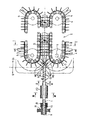
以下、図1を参照して本発明の一実施例について説明する。1は充填ノズルであり、該充填ノズル1には一枚天然腸部C1と収縮天然腸部C2とに区分された天然腸Cが装着されている。収縮天然腸部とは天然腸を長手方向に縮めてジャバラ状の形態をなしている部分である。一枚天然腸部とは、天然腸を長手方向に引き伸ばしてまっすぐな形態をなしている部分である。充填ノズル1は充填物を連続的に供給するための充填ポンプ(図示しない)から送り出された充填物を受け入れて先端から吐出するものである。該充填ノズルは軸線X回りに連続回転可能に設けられており、この実施例では軸線X方向にわたって丸パイプ状の同一断面形状を有している。
【0010】
2はピンチ装置であり、該ピンチ装置2は充填物が充填された充填天然腸Sを挟搾して充填ノズルの前方へ搬送するものである。ピンチ装置2は、充填天然腸の外周から対向して挟搾する一対のピンチャー部材3A、3Aからなるピンチャー3と、該ピンチャー3を連続的に移動する移動手段としての巻掛伝動手段4とを有している。
【0011】
巻掛伝動手段4は、軸5、6と該軸5、6に取り付けられたスプロケット7、7間に張設されたチェーン8とからなり、ピンチャー部材の移動中心としての軸5はピンチャー部材3Aが充填ノズル先端1aの後方領域9から前方領域10に向かって移動する様に、充填ノズル1の軸線Xの側方かつ、充填ノズル先端1aの前方領域10に位置する。
【0012】
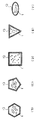
図2の(A)をも参照して、ピンチャー部材3Aには、V字状切欠き部3aが設けられており、該切欠き部3aの開口寸法dは充填天然腸Sの外径以上の大きさに設定されており、開口部半径rは充填ノズル1の先端と軸5間の距離より大となるよう構成されている。11はノズル回転手段としての駆動機構であり、該駆動機構11は図示せぬモーターからの駆動を受けて、充填ノズル1を回転駆動するものである。駆動機構11には充填ノズル1がナット12によって取り付けられており、軸線X方向に延びて貫通する充填物通路孔13が設けられている。
【0013】
以上のように構成された本発明の一実施例にかかるソーセージ等の連鎖状の食品の製造装置について、その作用を説明する。充填ノズル1に天然腸Cを装着し、収縮天然腸部C2を手で充填ノズル1の前方に引き出して、充填ノズル1上に一枚天然腸部C1を形成させると同時に、該一枚天然腸部C1を充填ノズル先端1aから所定長さを垂下させる。装置の運転が開始されると、充填ノズル先端1aから垂下した一枚天然腸部C1に充填ノズル1の先端から連続的に定量の充填物が吐出され、形成された充填天然腸Sは充填圧力によって、充填ノズル1上の一枚天然腸部C1を引き出しながらピンチ装置2へ向かって移動する。
【0014】
ピンチ装置2のピンチャー3の切欠き部3aが充填ノズル1上の一枚天然腸部C1の外周に近接して、充填ノズル先端1aの前方領域10に向かって移動してゆき、充填ノズル先端1aに近い位置にて充填天然腸Sを挟搾開始する。ピンチャー部材3Aは軸5を中心にした移動を続けて充填天然腸Sの挟搾を完了させた後、挟搾状態を保持したまま充填天然腸Sを軸線Xに沿って引っ張り、搬送する。充填天然腸Sをピンチャー3で引っ張り搬送するので充填ノズル1上の一枚天然腸部C1は軸線X方向に引き伸ばされつつ、移動して収縮天然腸部C2を引っ張り、該収縮天然腸部C2は引き伸ばされつつ、その径を縮小させられて、一枚天然腸部C1となる。天然腸の径の縮小を以下「縮径」という。充填ノズル1上で、軸線Xに沿って形成されている一枚天然腸部C1は常に引っ張られているので、充填ノズル1の外周への接触程度を強め充填ノズル1と共に回転しながら、充填ノズル先端1aから引き出されてゆく。充填天然腸Sは充填ノズル1と共に連続回転する一枚天然腸部C1によって回転駆動され、前述したピンチャー3による挟搾箇所の天然腸に継続した捻りを与える。充填ノズル1の外周に接触した一枚天然腸部C1の内周面C3は充填ノズル1から回転力が付与される。この接触を密着した態様にすると、充填ノズル1の回転がより伝わりやすい。
【0015】
後続するピンチャー3による次なる挟搾が終了するまで、上記天然腸の捻りは続けられる。ピンチャー3は一定速度で連続移動を継続し、充填ポンプは充填ノズル先端1aから引っ張り出された一枚天然腸部C1内に充填物を連続的に吐出し、充填天然腸Sが形成されてゆく。ピンチャー3は一定速度で連続して移動しており、該ピンチャー3によって引き伸ばされて径を縮めようとしながら移動する一枚天然腸部内に一定量の充填物を連続吐出する。このため、充填径のばらつきが少ない充填天然腸Sが形成されるものとなる。チェーン8に所定間隔で設けられた後続のピンチャー3は、充填ノズル先端1aに近い位置にて充填天然腸Sを挟搾し始める。該充填ノズル先端1aに近い位置にある充填天然腸Sの充填径は未だ小さいので、容易に捻りが発生し、捻りの発生位置が充填ノズル先端1aに近いので、回転する充填ノズル1上の一枚天然腸部C1の回転が該捻り発生位置に伝わり易く、ピンチャー3による挟搾箇所に十分な捻りを確実に与えるものとなっている。ピンチャー3による充填天然腸Sの搬送速度と充填物の吐出量との関係で、ピンチャー3は充填ノズル1の外径より大きな充填天然腸部位を挟搾することもある。(図4参照)
【0016】
図2の(C)を参照して、充填ノズル1の非回転状態において、充填ノズル1に装着された収縮天然腸部C2は軸線X方向に圧縮されたジャバラ状となって、充填ノズルから垂下する。充填ノズル1の外径よりも、通常、収縮天然腸部C2の内径は十分に大きい。図2の(B)を参照して、回転中の充填ノズル1上の一枚天然腸部C1は既述の如く軸線X方向に引き伸ばされて径が縮小し、充填ノズル1の外周に実質的に密着する。一枚天然腸部C1は充填ノズル1の外周と局部的に僅かな隙間や、皮膜の重なり部があっても、全体として充填ノズル1に一枚天然腸部C1の内周面C3が接触しておれば良い。
【0017】
図1に戻って、回転する充填ノズル1から制動力を受けつつ、充填ノズル先端1aへ向かって移動する一枚天然腸部C1は充填天然腸Sを回転駆動することによって充填ノズル1の外周に巻き付く様にねじれKを生じ、密着力を増加させる。一様な形状を持つ充填ノズル1外周に一枚天然腸部C1を軸線Xに沿って一様に接触好ましくは密着させるので、充填天然腸Sを回転駆動するに必要な充填ノズル1からの制動力を受けても、一枚天然腸部C1は破損することなく充填ノズル1の外周を滑って充填ノズル先端1aから引き出されてゆく。一枚天然腸部C1が引き出されるに連れて、充填ノズル先端1aからの充填ノズル1上の一枚天然腸部C1の長さが増大する。通常、この軸線X方向の接触長さを所望の範囲内に維持することが好ましいので、収縮天然腸部C2の後端を充填ノズル先端1aへ向けて押進させる。
【0018】
使用される天然腸、例えば羊腸の場合、その長さと直径は、例えば1本8mであってその全長にわたって18mmから20mmと直径が変化する。充填ノズル1の直径との関係で、天然腸Cをより縮径させたい場合には、後述する実施例装置での係合部材としての制動部材を用いて天然腸Cへの制動力を増加させることによって達成できる。充填天然腸Sでの捻り発生のしにくさ(天然腸種類、天然腸の状態、充填天然腸サイズ他)に応じて、充填ノズル先端1aをピンチ装置2へ、図示された位置よりも離反あるいは接近して配置する。接近配置の場合、充填ノズル先端1aの後方領域から前方領域に向かって移動するピンチャー3の切り欠き部3a内に充填ノズル先端1aが位置するので、切り欠き部3aによる充填天然腸Sの挟搾開始位置がより充填ノズル先端1aに接近し、捻りの発生をより容易にするものである。
【0019】
図3の(A)ないし図3の(E)を参照して、本発明では種々な外周形状の充填ノズル1を用い得るものである。例えば、充填ノズル1の断面形状は、真円のみならず図3の(A)に示すように楕円形状でも良い。また、図3の(B)に示すように三角形、(C)に示すように四角形、(D)に示すように五角形、(E)に示すように六角形、等のように多角形としても良い。図3に示すような充填ノズル1の断面形状によると、真円断面形状と比べて充填ノズル1と一枚天然腸部C1との回転方向のスリップが低減されるものとなる。
【0020】
更に、図4の(A)に示すように、充填ノズル1の外周に長手方向(軸線X方向)に沿った溝1Sを多数(この例では10個)形成したもの、あるいは、図4の(B)に示すように、充填ノズル1の外周に長手方向に沿った突起1Tを付けたもの、図4の(C)に示すように、充填ノズル1の外周に長手方向に沿った平面部1S′を4個形成したもの、などであって、いずれの充填ノズル1にあっても、収縮天然腸部C2が引き伸ばされることによって、その天然腸の径(18〜20mm)が充填ノズル1の外径、例えば10mm迄縮小して一枚天然腸部C1となって該充填ノズル1の外周に接触するものである。なお、図4に示すような充填ノズル1の形状によると、真円断面形状と比べて充填ノズル1と一枚天然腸部C1との回転方向のスリップが低減されるものとなる。
【0021】
なお、ピンチ装置の巻掛伝動手段は図示のスプロケットとチェーンの構成のみならず、例えば、タイミングプーリーとタイミングベルトなどの公知の巻掛伝動手段も使えるものである。
【0022】
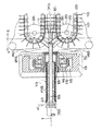
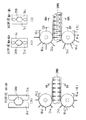
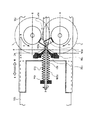
次に、本発明の他の実施例について図5ないし図8を用いて説明する。図5ないし図8は本発明の一実施例にかかる天然腸を使用したソーセージ等の連鎖状の食品の製造方法及び装置について説明する図である。尚、この中で図5は本発明の製造装置の概略正面図であり、図6はその平面図、図7及び図8は充填天然腸に捻り部を形成する作用を説明するための拡大部分断面図である。
【0023】
図において、101は練り状のソーセージ原料等の充填物を加圧供給する充填ポンプ、102は充填ポンプ101から供給された充填物を収容する充填ブロック、103は充填ポンプ101から供給された充填物を後述の天然腸104に充填する丸管状の充填ノズルである。充填ノズル103には孔103aが形成されており、該孔103aが充填ブロック102内に位置しているときに充填物が該孔103aを介して充填ノズル103内に送り込まれるものである。充填ノズル103には羊腸や豚腸からなる天然腸104が装着されている。
【0024】
充填ポンプ101は、供給量が可変となっている。充填ポンプ101を駆動する充填ポンプ駆動機構は以下のとおりである。充填ポンプ用モーター105の回転を変速機106を介して減速機107へ伝達する。ポンプ速度の変速手段としての変速機106は変速プーリー106A、ベルト106B、変速プーリー106Cとからなっている。このため、充填ポンプ用モーター105の回転は変速プーリー106A、ベルト106Bを介して変速プーリー106Cに伝達され、該変速プーリー106Cの回転が減速機107へ入力される。電磁クラッチ106Dは変速プーリー106Cと減速機107との回転伝達をカット、オンさせるものである。使用する天然腸のサイズとピンチ装置の速度に合わせて、ポンプ供給量を所望に設定できる。
【0025】
減速機107の出力回転はカップリング108を介して充填ポンプ101の図示しない回転軸と連結している。上述した可変機構を速比不変なベルト伝動機構に変えて、上記モータ105の代わりに変速モーターを用いえる。あるいは、変速モータ又は減速機付の変速モータの各出力軸を充填ポンプ101の上記回転軸に直結して用いてもよい。変速モータとは例えばサーボモータやインバータ制御によるモータである。
【0026】
充填ノズル103は回転されるものとなっている。ノズル回転手段としての回転機構は以下のとおりである。充填ノズル回転用モーター109は、変速可能なモーターであり、充填ノズル103の回転数を所望に設定できる。該モーター109のプーリー110にはベルト111が巻き掛けられており、該ベルト111は充填ノズル回転プーリー112に巻掛けられている。充填ノズル回転プーリー112はベッド113上に固定されたハウジング114に回転可能に保持されている。充填ノズル回転プーリー112にはクラッチ爪112Aが設けられている。充填ノズル103は回転継ぎ手115を介してエアシリンダー116のシリンダロッド116Aに連結され、これによって充填ノズル103は往復動される。充填ノズル103には前記クラッチ爪112Aと係合するクラッチ爪103Bが設けられている。このため、エアシリンダー116によって充填ノズル103が移動された時にクラッチ爪112A、103Bが係合し、充填ノズル回転プーリー112の回転が充填ノズル103に伝達されるものである。
【0027】
充填ノズル103には天然腸104が収縮天然腸部104Aと一枚天然腸部104Bとに区分されて装着される。そして、収縮天然腸部104Aを充填ノズル103の先端側に押す天然腸押進部材としての腸押し117が充填ノズル103に嵌め込まれている。腸押し117はロッド118を介してエアシリンダー119に連結されており、該エアシリンダー119によって腸押し117は移動されるものとなっている。また、充填ノズル103には腸押し117が当接する段部103Cが設けられており、充填ノズル103の移動と共に腸押し117が移動されるものとなっている。このため、充填ノズル103の移動によって腸押し117が移動され、充填ノズル103が前進完了した位置で腸押し117の位置は図5の初期位置IPとなっている。腸押し117は充填ノズル103に回転自在に装着されており、腸押し117の外周溝にロッド118に固着された押し部材118aが嵌合しており、ロッド118の往復動作を腸押し117に伝える。
【0028】
ベッド113上には腸の後端を検出する検出手段120が設けられている。検出手段120は光電センサー120Aからなるものであり、充填ノズル103に装着された天然腸104の収縮天然腸部104Aによって光が遮断された時には天然腸104の存在が確認され、光が通過した時には収縮天然腸部104Aがなくなり一枚天然腸部104Bとなったことを知るものである。検出手段120はストッパー部120Bを有しており、該ストッパー部120Bと押し部材118aとが接触することにより腸押し117の移動が停止されるものとなっている。
【0029】
ベッド113上には、更にハウジング121が設けられ、該ハウジング121内には係合部材としての制動部材122がプーリー123によって回転可能に設けられている。これを図7でもって更に詳しく説明すると、ハウジング121内にはプーリー123が軸受124によって回転可能に保持されている。プーリー123の中心穴内には制動部材122が設けられている。制動部材122は制動部材抑え125によって固定されている。制動部材122は合成ゴムからなるリング状の部材からなっており、中心には充填ノズル103が貫通する丸い穴の開口を有している。その開口径は充填ノズル103と同径又は小径とする。制動部材抑え125は、充填ノズル103上の収縮天然腸部104Aを部分的に収容し、充填ノズル103の軸線Xに対して、該収縮天然腸部104Aの外周と接触して回転駆動する収縮天然腸回転部材を兼ねるものである。
【0030】
係合部材としての制動部材122を軸線X回りに回転させる回転駆動機構は以下のとおりである。プーリー123にはベルト126が巻掛けられ、該ベルト126は制動部材用モーター127のプーリー128に巻き掛けられている。制動部材用モーター127はインバータによって変速される変速モーターであり、制動部材122の回転数を所望に設定でき、このモータをサーボモーターに置換できる。
【0031】
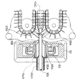
また、ベッド113上には一対のピンチャー部材129A、129Aからなるピンチャー129とその移動手段130とからなるピンチ装置131が設けられている。また、図6を参照して、移動手段130は、回転軸137と、回転軸137に取り付けられたスプロケット132とアイドルスプロケット132Aと、スプロケット132とアイドルスプロケット132Aに各々巻掛けられたチェーン133と、該チェーン133に取り付けられた多数のラグ134とからなっている。ピンチャー部材129Aは所定の間隔毎に複数個、チェーン133に取り付けられており、チェーン133と共に移動しながら対向する2個のピンチャー部材129Aによって充填天然腸を挟搾するものである。ピンチ装置駆動機構は、ピンチ用モーター131A、変速機135、減速機136からなっている。
【0032】
スプロケット132は、変速機135、減速機136、回転軸137を介してピンチ用モーター131Aにより回転されるものとなっている。これによってピンチャー部材129Aの移動速度を所望に設定できる。使用する天然腸のサイズ、種類に合わせて、ピンチ装置の速度(生産量)を所望に設定できる。上述した駆動機構はインバータによって変速される変速モータやサーボモータに代え得るものである。また、変速モータや減速機付き変速モータの出力軸を回転軸137に直結して用い得るものである。ピンチャー部材129AはV字状の溝部を有し、該溝部で充填天然腸を対向する2個のピンチャー部材によって挟搾する。
【0033】
以上に説明した本発明の一実施例にかかるソーセージ等の連鎖状の食品の製造装置について、主に図7及び図8を参照して以下にその作用を説明する。まず、充填ノズル103に天然腸104を装着する。この場合、図5に示すように、収縮天然腸部104Aと、一枚天然腸部104Bとに区分して装着する。そして、エアシリンダー116を作動させて充填ノズル103及び一枚天然腸部104Bを制動部材122の開口に貫通させる。この時、腸押し117は充填ノズル103の段部103Cに押されて初期位置IPまで移動される。ロッド118が腸押し117と一緒に移動されるように、エアシリンダ119の内部は外気と導通状態になっている。
【0034】
次に、充填ポンプ101とピンチ装置131とが作動開始し、充填物が充填ノズル103の先端から吐出される。すると、充填ノズル103から一枚天然腸部104Bが引き出され、その中に充填物が充填されて充填天然腸104Cが形成される。この充填天然腸104Cは最初矢印方向に移動するピンチ装置131のラグ134によって挟まれて引っ張られる。そして次に、ピンチャー129によって充填天然腸104Cを挟搾する。充填天然腸104Cが一枚天然腸部104Bを引っ張ると、一枚天然腸部104Bが充填ノズル103から制動されつつ滑りながら移動し、合わせて該一枚天然腸部104Bは制動部材122の開口部とも係合しているので、更なる制動力を制動部材122からも受ける。一枚天然腸部104Bは特にピンチャー129と制動部材122との間で引きのばされるので、充填ノズル103に装着された該一枚天然腸部104Bはより強くその径を縮小しようとして、一枚天然腸部104Bは充填ノズル103の外周に接触しそして密着する。このため、充填ノズル103の回転が該縮径された一枚天然腸部104Bを介して充填天然腸104Cに伝達され、結局充填ノズル103の回転によって充填天然腸104Cが回転されるものとなる。このため、ピンチャー129によって挟搾された充填天然腸104Cの部分に捻りが生じて連鎖状となる。
【0035】
本発明の一つは充填ノズル上の一枚天然腸部が縮径された状態で充填ノズルとともに回転すれば良い。係合部材としての制動部材が回転駆動機構で回転される本実施例装置において、仮に、制動部材122が実質的な回転力を一枚天然腸部104Bの外周に付与しているとしても、本発明の範囲から外れるものではない。一枚天然腸部の径をより多く減少させようとするために、充填ノズル上の天然腸と係合する係合部材は、種々の形態を採り得るものである。例えば、本実施例に示すように、一枚天然腸部104Bの外周に接する形態や、後述の図9に示される(制動部材122A)ように、充填ノズル103の外径よりも大きな穴径を有し、主に収縮天然腸に接触する形態がある。
【0036】
上記ピンチャー129の作動軌跡について更に詳しく説明する。図7に示すように、ピンチャー129のピンチャー部材129Aは、充填ノズル103の先端(吐出端)を基準として後方の領域Pから前方の領域Qへ向けて移動する。そして、充填ノズル103の先端の前方の噛み合い位置Rで噛み合うものとなっている。ここで、噛み合い位置Rは充填ノズル103の先端に近い程好ましいものである。すなわち、噛み合い位置Rが充填ノズル103の先端に近い程充填天然腸104Cに確実な捻りが生ずるものである。これを図8で説明すると、ピンチャー部材129AのV溝の谷部の回転軌跡が充填ノズル103の先端の外周に接するような軌跡となると、ピンチャー129の噛み合い位置Rが充填ノズル103の先端に近接したものとなる。このような状態でピンチャー129が充填天然腸104Cを挟搾すると、充填天然腸104Cの捻りの位置が該挟搾部分に特定され、捻りの位置が確実となる上、充填天然腸104Cの破れもなくなるものである。
【0037】
充填ノズル103の上の天然腸104の収縮天然腸部104Aが無くなると、検出手段120の光電センサー120Aが作動して電磁クラッチ106Dを切り、充填ポンプ101の作動を停止させる。そして、エアシリンダー116が後退作動して充填ノズル103を図6の右方に移動させ、同時にエアシリンダー119も後退動作して腸押し117を移動させ、充填作業を終了させる。この光電センサ120Aは透過型を用いているが、センサのタイプは限定されない。
【0038】
次に、腸押し117の作用について述べると、充填ノズル103上の天然腸104が順次引き出されると、一枚天然腸部104Bの長さが長くなるので、この長さを減らすために、エアシリンダー119を作動させて、ロッド118の押し部材118aがストッパ部120Bにぶつかる迄移動させる。この移動によって、初期位置IPに停止していた腸押し117は所定位置迄移動し、収縮天然腸部104Aの後端を段階的に押し進めることになる。腸押し117は上記所定位置にて、全ての充填が終了する迄、停止している。尚、初期位置IPから所定位置迄を多段階に押し進めても良い。
【0039】
本実施例では、充填ノズル103と腸押し117とをエアシリンダによって作動させたが、これに代えて、これらを手で作動させることもできる。エアシリンダ116、119内を大気に導通させ、エアシリンダ116のロッド116Aにハンドルを固着し、ロッド118にも別のハンドルを固着し、これらのハンドルを図5の左右方向に押すことによって、充填ノズル103と腸押し117とを手で作動できる。検出手段の光電センサー120Aの設置位置を、ストッパ部120Bにて停止している押し部材118aを検出できる位置に変更し、その位置にて光電センサー120Aが押し部材118aを検出するように作動させても良い。手で腸押し117を作動させる使い方において、この検出方法によって充填ポンプ101を停止させるのは有効である。
【0040】
上述の充填作用時においては、制動部材122を制動部材用モータ127によって回転させるものとなっているが、制動部材122は必ずしも強制的に回転させる必要はなく、例えば制動部材122を回転可能に保持させて充填ノズル103の回転によって該制動部材122を回転させる構造としても良い。また、上述までの実施例装置において、後述の他の実施例装置(図16及び図17参照)の充填ノズルと制動部材との構成を用いても良い。
【0041】
上記図1ないし図8に示す実施例では、例えば、充填ノズルが曲がったり、あるいは剛性が少なかったりして上下左右に揺れ動き、ピンチャーと接触するおそれが生じる場合もある。そこで、図9に示すように、充填ノズル103の振れを防止する部材を取り付けてピンチャー部材129Aとの接触を防止する構造とすることもできる。すなわち、ハウジング121内に設けられたプーリー123の内周面には制動部材122Aを有する振れ防止部材抑え125Aによって、振れ防止部材138がプーリー123と一体的に回転するように固定されている。振れ防止部材138の内径は、充填ノズル103の外径より大きく設定されている。充填ノズル103に振れが生じても、振れ防止部材138の穴部によって振れ量が規制され、充填ノズル103がピンチャー部材129Aに接触するのを防ぐものである。振れ防止部材138の材質は適宜選択採用されるものであるが、変形が生じにくい合成樹脂が好ましい。制動部材122Aに変形しにくい材質を用いるならば、振れ防止部材138を設ける必要はない。制動部材122Aは、充填天然腸104Cに引っ張られて移動する一枚天然腸部104Bが、収縮天然腸部104Aを引き伸ばす過程で、天然腸Cをしごいて、一枚天然腸部104Bの微小な重なりをほぐす。
【0042】
図5ないし図8で示す実施例では、ピンチ装置が充填天然腸を挾搾しながら搬送することによって、天然腸を縮径させているが、本発明は上述の実施例に限定されるものではなく、以下に説明するように、充填天然腸を挾搾するピンチ装置とは別に設けた搬送装置によって天然腸を縮径させる構造とすることもできる。
【0043】
図10ないし図12を参照して、充填ノズル61は回転自在とはなっているものの、往復動はしないものとなっている。充填ノズル61には一枚天然腸部66Bと収縮天然腸部66Aとに区分された天然腸66が装着される。充填ノズル61には充填ポンプ62から定量の充填物が連続的に供給される。充填ポンプ62は回転式の計量ポンプ、例えば歯車式ポンプである。また、充填ノズル61を回転させるノズル回転手段は、充填ノズル回転用変速モーター63に取り付けられた伝動歯車64が伝動歯車付き駆動部材65に噛合し、これによって該伝動歯車付き駆動部材65に取り付けられた充填ノズル61が回転するようになっている。充填ポンプ62のポンプ軸62Aには充填ポンプ用変速モータ62Bの出力軸が接続されている。充填ポンプ62は変速モータ62Bを有する駆動機構によって所望の速度に設定され、使用する天然腸のサイズや搬送装置の搬送速度に合った、所定の充填量を充填ノズルに供給する。
【0044】
また、図5ないし図8で示す実施例では腸押しをエアシリンダーによって自動的に移動させているが、この実施例では、充填ノズル61に装着された天然腸66は、作業員が手動で天然腸押進部材としての腸押しカラー67を充填ノズル61の先端61Aへ向けて押すようになっている。腸押しカラー67の移動を停止させるため、ストッパー68が設けられており、該ストッパー68は充填ノズル61に装着された天然腸66の後端を検出する光電センサ69Aとともに検出手段69を構成している。検出手段69からの信号によって、充填ポンプ62を駆動する充填ポンプ用変速モータ62Bを停止する。検出手段69の作用は前述の実施例と実質的に同じである。
【0045】
ピンチ装置70は充填ノズル61の先端61Aに近接して設けられており、その下流には、充填物が充填された充填天然腸66Cを挟持して、所定速度で連続的に搬送する搬送装置71が設けられており、これらの装置は取付け部材72に取り付けられている。取付け部材72はピン73を介して充填ノズル61が取り付けられたハウジング74に矢印D方向に回動自在に取付けられている。
【0046】
この実施例におけるピンチ装置70は、上下に対向して設けられた2個の回転部材70Aに凹溝70Eを形成したピンチャー部材70Cを取り付けた構成となっており、該2個のピンチャー部材70Cの凹溝70Eによって充填天然腸66Cに挟搾部を形成するものである。ピンチ装置70を駆動するピンチ装置駆動機構が取付部材72に設けられている。ピンチ装置駆動機構はピンチャー用モータ75と一対のギャ76を有している。ピンチ装置70の一方の回転部材70Aはピンチャー用モーター75の軸に接続された回転軸70Dに取り付けられており、該モーター75によって、設定された所望の回転数でもって回転され、ギヤー76は対向する他方の回転部材70Aを回転させるためのものである。上記した回転部材70Aと回転軸70Dはピンチャー70Bを移動させる移動手段である。回転部材70Aを除いて、ピンチャー部材70Cを回転軸70Dに取り付けても良い。
【0047】
ピンチャー部材70Cは充填ノズル61の先端61Aの後方領域Pから前方領域Qに向かって移動するように、その移動中心としての回転軸70Dが充填ノズル61の軸線Xに関して対称な位置に配されている。ピンチャー70Bを構成する一対のピンチャー部材70C、70Cは回転軸70Dとともに回転し、搬送装置71によって搬送されてゆく充填天然腸66Cを挟搾した後その挟搾を解除する迄、挾搾部位を搬送する。ピンチャー部材70Cの噛合い位置Rが充填ノズル61の先端61Aに近接している構成、並びにそれによる作用については、前述した他の実施例と実質的に同じである。
【0048】
ノズル回転手段は、ピンチャー70Bによって挟搾された充填天然腸66Cの部位に捻りを与えるように、充填ノズル61を連続的に回転させる。充填ノズル61を連続回転させずに、ピンチャー70Bが充填天然腸66Cを挟搾している間のみで捻りの形成を完成させるように、変速モータ63は充填ノズル61を間歇的に回転させても良い。
【0049】
本実施例ではソーセージの長さを所望に変えることができる。搬送装置71によって搬送される充填天然腸66Cに対して、ピンチャー70Bの挟搾周期を所望に設定することによって、所望な充填天然腸の捻りの間隔(ソーセージの長さ)が得られる。ピンチャー部材70Cの回転数は、変速モーターであるピンチャー用モーター75によって、搬送装置71の搬送速度は、搬送装置71を駆動する変速モータである搬送装置用モーター77によって、各々所望に設定できる。ピンチャー部材70Cは、等速で連続回転し、この結果、ピンチャー部材70Cが充填天然腸66Cを挟搾している時のピンチャー部材70Cの速度と充填天然腸66Cの搬送速度との間に速度差が生じるが、充填天然腸66Cを挟搾する本発明においては、速度差があっても確実に捻ることができる。ピンチャー部材70Cを不等速回転することもできる。この不等速回転の場合は、充填天然腸66Cを挟搾中のピンチャー部材70Cの速度を充填天然腸66Cの搬送速度と同速度にできる。モーター75は不等速回転となるように適宜な制御装置で制御される。
【0050】
また、回転部材70Aに取り付けられるピンチャー部材70Cの数は図示のように1個でも良いが、2個以上とすることもできる。所望の数のピンチャー部材が等分割角度で固設された回転部材、たとえば、2個のピンチャー部材70Cが180度間隔で固設された回転部材70Aに置き換えて用いるならば、ソーセージの長さの変更によって生じる、天然腸搬送速度とピンチャー部材の挾搾速度との間の速度差を減少できる。必要に応じて、回転部材70Aが着脱可能に取付けられた一対の回転軸70D、70Dの軸間距離を変更することもできる。
【0051】
搬送装置71は上下に対向して設けられたチェーン71Aをスプロケット71Bでエンドレスに回転させ、該チェーン71Aに設けられたラグ71Cで充填天然腸66Cを挟持することにより該充填天然腸66Cを連続的に一定速度で搬送するものである。なお、充填天然腸66Cを搬送させて、充填ノズル61に装着された一枚天然腸部66Bを引っ張って移動させることによって、天然腸66を縮径させて充填ノズル61に接触、好ましくは密着させることは前述のとおりであるから、ここでは詳細な説明は省略する。
【0052】
ラグ71Cによる充填天然腸66Cの挟持は、スリップが極力防止されることが必要となる。そこで、図12に示すような構造としている。まず、図12の(A)、(C)、(D)では、対向して配置されたラグ71Cが相互に喰い違いの位置に配置されたものである。この構造によると、両チェーン上のラグ71C同士が衝突しないので、充填天然腸66Cを強く挟持することができるものとなる。また、図12の(B)、(E)では、対向して配置されたラグ71C同士を同じ位置に配置したものである。この構造によっても、充填天然腸66Cのスリップが防止されるものである。
【0053】
上述のように、充填天然腸66Cのスリップを防止することは、その分だけ搬送装置71の長さを短くできるということを意味し、これによって取り付け部材72の小型化が得られ、取り付け部材72の開閉動作を迅速に行える。本実施例装置において、充填ノズル61が貫通しており、充填ノズル61に装着された天然腸66と係合する係合部材を更に設けることもできる。該係合部材は充填ノズル61によって回転駆動させても良い。また、係合部材を充填ノズル61の軸線X回りに回転させる回転駆動機構を更に設けることもできる。この回転駆動機構に係合部材を回転させるモータを備えても良い。このモータを変速可能なモータとしても良い。
【0054】
更にまた、天然腸押進部材としての腸押しカラー67を特開平6ー7073号や特開平7ー123906号で公知な方法や、前述の実施例装置と同じ方法でもって、段階的に移動させるように構成することもできる。連続的に回転して充填量を供給する充填ポンプ、連続的に等速回転する充填ノズル、連続的に等速回転するピンチャー部材を有するピンチ装置、連続的に一定で移動する巻掛走行体を有する搬送装置で構成するならば、複雑な制御を必要としない、簡潔で高速運転可能かつ廉価な装置となる。
【0055】
本発明は、また図13に示すような実施例とすることもできる。この実施例では、所望の長さのソーセージを得る点において前記図10、図11に示す実施例と同様だが、以下に説明するようにピンチ装置の構成が相違するものである。ピンチ装置81は、チェーン82に等間隔で設けられた二対のピンチャー部材83A、83Bと、該ピンチャー部材83A、83Bを移動させる回転軸80、チェーン82とスプロケット84、とからなる移動手段85を有する。上下に対向して噛み合ったピンチャー部材83Aは充填ノズル86の前方へ直線に移動した後に該噛み合いを解除する。充填ノズル86の軸線Xに関して対称位置に設けられた一対のピンチャー部材83A、83A並びに一対のピンチャー部材83B、83Bがピンチャー83を構成する。搬送装置87は対向した2つの平ベルト87Aからなる。ここで、87Cは、搬送装置87を駆動する変速モータである。
【0056】
充填ノズル86は図13の(B)に示すように、四角状断面を有するパイプであり、係合部材としての制動部材88は丸穴の貫通孔を有し、充填ノズル86の四つの各角と接触する。制動部材88は充填ノズル86の回転によってブラケット91内で充填ノズル86と一緒に回転する。制動部材88は収縮天然部89Aのジャバラ状を確実に引き伸ばして一枚天然腸部89Bにするために天然腸89の外面と係合する。
【0057】
この実施例は、ピンチャー部材83A、83Bの挾搾周期を所望に設定することによって、所望の捻りの間隔を得る点において、前記図10、図11の実施例と同様である。また、充填天然腸89Cを挾搾したピンチャー部材83A、83Bは直動する距離を有するので、搬送装置87の平ベルト87Aの移動速度とピンチャー部材83A、83Bの直線動の速度とを同速度とすることが望ましい。ピンチャー用変速モーター90は、2対のピンチャー部材83A、83Bが各々交互に所望の周期で充填天然腸89Cを挾搾し、かつ、挾搾したピンチャー部材83A、83Bが平ベルト87Aの移動速度と同速度で移動する様に、ピンチ装置81を制御する。ここで、ピンチャー用変速モータ90はピンチ装置駆動機構を構成する。
【0058】
なお、上述の図13に示す実施例において、一対のピンチャー部材83A、83Aのみを有するチェーン82、82を備えたピンチ装置81であっても良い。ここで、チェーン82、スプロケット84はタイミングベルト、タイミングプーリーなどの公知のエンドレス部材に置き換えられるものである。これらの実施例によると、ピンチャー83が直線動領域を持つので、挾搾時間が長く捻りがより確実になるものである。
【0059】
前述までの実施例に示すピンチャーは、充填ノズルの軸線Xに関して対向する一対のピンチャー部材が相互に噛合うことによって充填天然腸の挟搾が行われるタイプのものであるが、本発明は以下の図14及び図15に示すような開閉式のピンチャーとすることもできる。すなわち、ピンチャー53は充填ノズル49の軸線Xの側方に設けられた開閉可能な一対のピンチャー部材53A、53Bを具備しており、ピンチャー53は一対の回転軸50、二対のスプロケット60、一対のエンドレスチェーン51、ブラケット52からなる移動手段に取り付けられている。また、垂直配置された回転軸50の上下方向に離間して設けられたスプロケット60、60に噛合して、エンドレスに回転するチェーン51、51間にわたってブラケット52を取り付ける。そして、ブラケット52にピンチャー53を開閉自在に取り付けるものである。
【0060】
ここで、ピンチャー53は、カム54およびカム54Aによって開閉されるものであり、その開閉機構は以下のとおりである。カム54に接してカムフォロア55が設けられている。該カムフォロア55は揺動するレバー56の端に設けられている。レバー56は支点57を中心として回転される。ピンチャー53は2枚のピンチャー部材53A、53Bからなっており、該ピンチャー部材53A、53Bが挟みのように交差することにより充填天然腸58Cを挟搾する。ピンチャー部材53A、53Bはレバー56の上端に連結されたリンク56A、56Bと各々連結されており、各連結はピンによってなされる。
【0061】
ピンチャー部材53A、53Bの開状態はカム54によって、閉状態はカム54Aによってなされる。ピンチャー部材53A、53Bの閉完了位置はピンチャー移動中心である回転軸50を通る軸線Y直近にあり、該Y軸に近接した位置に充填ノズル49の先端(吐出端)がある。この実施例では、係合部材としての制動部材48はブラケット47内に収容され、抑え部材46が該制動部材48を軸方向に対して固定している。制動部材48の穴径は充填ノズル49の外径に対して同じかあるいは小となっており、制動部材48は充填ノズル49の回転によって、ブラケット47内にて一緒に回転している。
【0062】
その作用を説明すると、カム54およびカム54Aにならって移動するカムフォロア55によって揺動レバー56が揺動され、該揺動するレバー56によりピンチャー部材53A、53Bが支点59を中心として回動する。これによってピンチャー部材53A、53Bが充填天然腸58Cを挟搾するものである。カム54によって開状態のピンチャー53がZ位置に達すると、この時点からカム54Aによる閉動作を開始し、ほぼY軸線上にて全閉となる。49は大径部49Aと小径部49Bとを有する丸形パイプ形状の充填ノズルである。大径部49Aには、天然腸58の収縮天然腸部58Aが、小径部49Bには一枚天然腸部58Bが装着される。この充填ノズル49によると収縮天然腸部58Aとのすきまが少ないので、充填ノズル49の回転が収縮天然腸部58Aへ伝わりやすい。他の構造については、前述までの実施例と実質的に同様であるから説明は省略する。
【0063】
このカム式の開閉ピンチャー53を使用した方式は、充填天然腸58Cを充填ノズルの先端の直後で挟搾開始でき、挟搾完了迄のピンチャーの移動距離を極小とできるので、挾搾完了位置を充填ノズル49の先端真近となしえる。本発明においては、充填ポンプ装置、充填ノズル、ピンチ装置、搬送装置の作動は、上述の実施例に限定されるものではなく、例えば、以下に説明するような態様例とすることもできる。図1ないし図9、及び図14、図15に示される実施例装置において、連続移動するピンチャーに対して、充填ノズルの回転状態は連続または間歇のいずれを採用しても良い。
【0064】
図10ないし図13に示される実施例において、連続駆動される搬送装置に対して、充填物を間欠定量供給するために充填ポンプを間欠駆動する構造とすることもできる。また、間欠駆動する搬送装置に対して充填物を間欠吐出させるために、充填ポンプの間欠駆動を間欠駆動する搬送装置に同期させる構造とすることもできる。充填ノズルの回転状態は、上述と同じく、連続または間欠のいずれを採用しても良い。
【0065】
本発明においては、既述した全ての実施例装置において開示されている充填ポンプを駆動するモータ、充填ノズルを回転させるモータ、係合部材(制動部材)を回転させるモータ、ピンチ装置を駆動させるモータ、並びに搬送装置を駆動させるモータに、各々変速モータ(減速機付き変速モータを含む)を採用できるものである。これらの各変速モータは、例えば、サーボモータやインバータ制御によるモータであり、モータの回転数を変更する公知の変速手段たとえば、インバータやサーボドライバーによって変速されるものである。
【0066】
図10に示す実施例では、充填ノズル61に制動部材が装着されていないので、天然腸66の一枚天然腸部66Bの長さを管理する必要がある。そこで、本発明は図16に示すように、係合部材としての制動部材142が充填ノズル141によって貫通されており、充填ノズル141上の縮径された天然腸143Aとの係合点が、充填ノズル軸線Xに対して平行なピンチャー部材移動中心線Hとピンチャー部材147Aの移動軌跡円Lとの交差点上の充填ノズル軸線Xに対する垂直線KCよりも後方(P方向)に位置して配されている構造とすることもできるものである。
【0067】
これを詳しく説明すると、充填ノズル141は図示しない回転手段によって回転されており、該充填ノズル141には天然腸143が装着されている。天然腸143を充填ノズル141の先端側へ押進するため、押進部材144が該充填ノズル141上を移動可能に設けられている。押進部材144は手動で押進させるものであるが、エアシリンダー等による機械的押進作動としても良い。また、充填ノズル141の先端側には制動部材142が装着されている。制動部材142は、ハウジング145に対して図の矢印M、Nで示す方向に接近、離反可能に設けられた移動ベッド146上に設置されている。移動ベッド146上には一対のピンチャー部材147Aからなるピンチャー147が設けられている。ピンチャー部材147Aは、図の矢印U方向に回転されている。制動部材142は、充填ノズル141の回転によって引き連れられて回転されるように回転可能に設けられている。制動部材142は移動ベッド145に固設されたブラケット148に回転可能に保持されている。尚、制動部材142は回転可能に設けられるものに限定されるものではなく、固定された構造としても良い。
【0068】
充填ノズル141の先端は制動部材142を貫通して図示の位置Oまで延び出しており、ピンチャー部材147Aの先端の移動軌跡円Lは位置Oを境界としてその前方領域Qから後方領域Pへ侵入し、そこからまた前方領域Qへ至る円形軌跡となっている。制動部材142の位置はピンチャー部材147Aの先端の移動軌跡円Lの前記後方領域Pの最奥端位置KCの外側となっている。
【0069】
図16に示す実施例では、制動部材142によって一枚天然腸部143Aに制動力を与えるので、図10に示す実施例のものと比べて、天然腸143の縮径による充填ノズル141への密着が更に良くなるものである。また、この実施例によると、制動部材142と充填ノズル141の先端との間の距離が定められたものとなるから、押進部材144によって収縮天然腸部143Bを制動部材142に常時押し付けていても一枚天然腸部143Aの長さの管理が確実となるものである。よって、収縮天然腸部143Bを押進部材144で多少ラフに押進することができる。
【0070】
また、天然腸143を充填ノズル141に装着するときには、移動ベッド146をハウジング145から離反する方向(図の矢印Mの方向)へ移動させることにより、簡単に天然腸143の装着作業を行うことができるものである。尚、制動部材142は、充填ノズル141から引き出される一枚天然腸部143Aに制動力を与える構造に限定されるものではなく、これに代えて、収縮天然腸部143Bのジャバラ状部分を確実に引き伸ばして一枚天然腸部143Aとするために天然腸143の外面と係合するような構造としても良い。
【0071】
図16に示す実施例では、充填ノズル141の先端が制動部材142を貫通してピンチャー147側へ延び出した構造となっているが、本発明は、図17に示すような、制動部材152が充填ノズル151によって貫通されており、充填ノズル151上の縮径された天然腸153Aとの係合点が、充填ノズル軸線Xに対して平行なピンチャー部材移動中心線Hとピンチャー部材157Aの移動軌跡円Lとの交差点上の充填ノズル軸線Xに対する垂直線KCよりも前方(矢印Q方向)に位置しているものも含むものである。
【0072】
これを詳しく説明すると、充填ノズル151は図示しない回転手段によって回転されており、該充填ノズル151には天然腸153が装着されている。天然腸153を充填ノズル151の先端側へ押進するため、押進部材154が該充填ノズル151上を移動可能に設けられている。押進部材154は手動で押進させるものであるが、エアシリンダー等による機械的押進作動としても良い。また、充填ノズル151の略先端には制動部材152が装着されている。制動部材152は、ハウジング155に対して図の矢印M、Nで示す方向に接近、離反可能に設けられた移動ベッド156上に設置されている。移動ベッド156上には一対のピンチャー部材157Aからなるピンチャー157が設けられている。ピンチャー部材157Aは、図の矢印U方向に回転されている。制動部材152は、充填ノズル151の回転によって引き連れられて回転されるように回転可能にブラケット148の内に設けられている。尚、制動部材152は充填ノズル151によって回転可能に設けられるものに限定されるものではなく、駆動機構によって強制的に回転される構造としても良い。
【0073】
充填ノズル151の先端は位置Oとなっており、ピンチャー部材157Aの先端の移動軌跡円Lは位置Oを境界としてその前方領域Qから後方領域Pへ侵入し、そこからまた前方領域Qへ至る円形軌跡となっている。制動部材152の位置はピンチャー部材157Aの先端の移動軌跡円Lの前記後方領域Pの最奥端位置KCの内側、即ち位置O寄りとなっている。
【0074】
図17に示す実施例では、縮径された一枚天然腸部153Aの長さが短くなっているが、その短くされた一枚天然腸部153Aでは回転力が不足であっても、制動部材152によって回転駆動力を増大させることによって十分に充填天然腸を回転させることができるものである。このように、充填ノズル151からのみの縮径された一枚天然腸部153Aに付加される充填ノズルの回転駆動力が小さくて、充填天然腸を回転させるに十分でない構成のものも本発明には含まれる。更に、押進部材154によって収縮天然腸部153Bを制動部材152側へ押進させる作用が簡単かつ容易に行えるものとなる。その理由は、収縮天然腸部153Bを多少ラフに押進させても、制動部材152によって押進させる終端が定まっているからである。
【0075】
また、天然腸153を充填ノズル151に装着するときには、移動ベッド156をハウジング155から離反する方向(図の矢印Mの方向)へ移動させることにより、簡単に天然腸153の装着作業を行うことができるものである。尚、制動部材152は、充填ノズル151から引き出される一枚天然腸部153Aに制動力を与える構造に限定されるものではなく、これに代えて、収縮天然腸部153Bのジャバラ状部分を確実に引き伸ばして一枚天然腸部153Aとするために天然腸153の外面に係合する係合部材としても良い。
【0076】
【発明の効果】
動物の腸である天然腸の有する伸長性を利用した本発明のソーセージ等の連鎖状の食品の製造方法及び装置によると、以下のような効果を奏する。
【0077】
1.充填径と充填の張り具合のばらつきの少ない天然腸ソーセージを高速生産できる。
2.天然腸ソーセージでありながら、充填径と充填の張り具合のばらつきの少ない形の良い、新規な定寸・定貫商品を高速生産することができる。
【0078】
3.径のばらつきの少ない天然腸を選別しながら使用する必要が減り、天然腸のコスト低減を図ることができる。
4.充填ノズルの回転を充填ノズル上の天然腸へ確実に伝えることができるものとなる。
5.ピンチャーで挟搾した箇所の充填天然腸にのみ捻りを生じさせ得るものとなり、不良率が低減し、腸の歩留りが向上する。
【0079】
6.ピンチャ−で充填天然腸を挟搾するときに、充填天然腸を絞ることによる破損が減少する。また、引き伸ばされた一枚天然腸部が充填ノズルへ過度に巻き付くことがなくなり、これによっても天然腸の破損が減少する。
【0080】
7.充填ノズルの回転が引っ張られた一枚天然腸部と充填天然腸とを介して、充填天然腸の挟搾部迄、確実に伝達されるものとなる。よって、捻り回数のバラツキが減少し、捻りの戻りも減少するものとなる。
【0081】
8.収縮天然腸部の径よりも小径な充填ノズルを使用することができるので、充填ノズルへの天然腸の装着が容易となり、作業時間の短縮が得られる。
【図面の簡単な説明】
【図1】 図1は、本発明の一実施例によるソーセージ等の連鎖状の食品の製造装置を示す一部破断平面図である。
【図2】 図2は、図1の充填装置の部分構造を示す図であり、(A)は図1のピンチャーの詳細図であり、(B)は図1の充填ノズルと一枚天然腸部を示す断面図であり、(C)は図1の充填ノズルと収縮天然腸部を示す断面図である。
【図3】 図3の(A)、(B)、(C)、(D)、(E)は、図1の充填ノズルとして使用される充填ノズル形状を示す断面図である。
【図4】 図4の(A)、(B)、(C)は、充填ノズルの他の実施例形状を示す図である。
【図5】 図5は、本発明の他の実施例になるソーセージ等の連鎖状の食品の製造装置を示す一部破断正面図である。
【図6】 図6は、図5の一部破断平面図である。
【図7】 図7は、図5及び図6の充填ノズル、制動部材及びピンチャー部分の拡大断面平面図である。
【図8】 図8は、ピンチャーの作用を説明するための図であり、図8(A)はピンチャーの正面図であり、図8(B)はピンチャー部分の拡大断面図である。
【図9】 図9は、充填ノズルの先端の振れを防止した本発明の実施例を示す断面平面図である。
【図10】 図10は、本発明の他の実施例を示す一部破断正面図である。
【図11】 図11は、図10の一部破断平面図である。
【図12】 図12の(A)、(B)、(C)、(D)、(E)は、ラグによって挾持された充填天然腸の断面の形状を説明するための図である。
【図13】 図13は、本発明の更に他の実施例を示す図であり、(A)は一部破断正面図であり、(B)は(A)の充填ノズルと制動部材の断面図である。
【図14】 図14は、本発明の更に他の実施例を示す一部破断平面図である。
【図15】 図15は、図14の一部破断側面図である。
【図16】 図16は、本発明の更に他の実施例を示す一部破断平面図である。
【図17】 図17は、本発明の更に他の実施例を示す一部破断平面図である。
【符合の説明】
1 充填ノズル 1a 充填ノズル先端
1S 溝 1S′ 平面部
1T 突起 IP 初期位置
C 天然腸 C1 一枚天然腸部
C2 収縮天然腸部 C3 内周面
2 ピンチ装置 S 充填天然腸
d 開口寸法 3 ピンチャー
3A ピンチャー部材 3a 切欠き部
4 巻掛伝動手段 5 軸
6 軸 7 スプロケット
8 チェーン 9 後方領域
10 前方領域 r 開口部半径
11 駆動機構(ノズル回転手段) 12 ナット
13 充填物通路孔 X 軸線
K ねじれ 46 抑え部材
47 ブラケット 48 制動部材
49 充填ノズル 50 回転軸
51 チェーン 52 ブラケット
53 ピンチャー 53A ピンチャー部材
53B ピンチャー部材 54 カム
54A カム 55 カムフォロワー
56 レバー 56A リンク
56B リンク 57 支点
58 天然腸 58A 収縮天然腸部
58B 一枚天然腸部 58C 充填天然腸
59 支点 60 スプロケット
61 充填ノズル 61A 先端
62 充填ポンプ 62A ポンプ軸
62B 充填ポンプ用変速モータ 63 充填ノズル回転用変速モータ
64 伝動歯車 65 伝動歯車付き駆動部材
66 天然腸 66A 収縮天然腸部
66B 一枚天然腸部 66C 充填天然腸
67 腸押しカラー 68 ストッパー
69 検出手段 69A 光電センサ
70 ピンチ装置 70A 回転部材
70B ピンチャー 70C ピンチャー部材
70D 回転軸 70E 凹溝
71 搬送装置 71A チェーン
71B スプロケット 71C ラグ
72 取付け部材 73 ピン
74 ハウジング 75 ピンチャー用モーター
76 ギャー 77 搬送装置用モーター
80 回転軸 81 ピンチ装置
82 チェーン 83 ピンチャー
83A ピンチャー部材 83B ピンチャー部材
84 スプロケット 85 移動手段
86 充填ノズル 87 搬送装置
87A 平ベルト 88 制動部材(係合部材)
89 天然腸 90 ピンチャー用変速モーター
91 ブラケット 101 充填ポンプ
102 充填ブロック 103 充填ノズル
103a 孔 103B クラッチ爪
103C 段部 104 天然腸
104A 収縮天然腸部 104B 一枚天然腸部
104C 充填天然腸 105 充填ポンプ用モーター
106 変速機 106A 変速プーリー
106B ベルト 106C 変速プーリー
106D 電磁クラッチ 107 減速機
108 カップリング 109 充填ノズル回転用モーター
110 プーリー 111 ベルト
112 充填ノズル回転プーリー 112A クラッチ爪
113 ベッド 114 ハウジング
115 回転継ぎ手 116 エアシリンダー
116A シリンダロッド 117 腸押し(天然腸押進部材)
118 ロッド 118a 押し部材
119 エアシリンダー 120 検出手段
120A 光電センサー 120B ストッパー部
121 ハウジング 122 制動部材(係合部材)
123 プーリー 124 軸受
125 制動部材抑え(収縮天然腸回転部材) 125A 振れ防止部材抑え
126 ベルト 127 制動部材用モーター
128 プーリー 129 ピンチャー
129A ピンチャー部材 130 移動手段
131 ピンチ装置 131A ピンチ用モータ
132 スプロケット 132A アイドルスプロケット
133 チェーン 134 ラグ
135 変速機 136 減速機
137 回転軸 138 振れ防止部材
141 充填ノズル 142 制動部材
143 天然腸 143A 一枚天然腸部
143B 収縮天然腸部 144 押進部材
145 ハウジング 146 移動ベッド
147 ピンチャー 147A ピンチャー部材
148 ブラケット 151 充填ノズル
152 制動部材 153 天然腸
153A 一枚天然腸部 153B 収縮天然腸部
154 押進部材 155 ハウジング
156 移動ベッド 157 ピンチャー
157A ピンチャー部材 158 ブラケット[0001]
BACKGROUND OF THE INVENTION
The present invention relates to a method and apparatus for producing foods such as chained sausages using natural intestine.
[0002]
[Prior art]
A conventional chain sausage product is manufactured by filling the filling into an animal intestine such as sheep intestine or pig intestine, that is, a natural intestine, or an artificial casing such as a cellulose casing or a collagen casing. In this case, the production method and apparatus are often different between the case where the natural intestine is used as the casing and the case where the artificial casing is used. That is, the natural intestine is easily broken when it is filled with a filling material or when the filled natural intestine is used as a link. Such a problem becomes more conspicuous in a filling apparatus that fills and squeezes a filling material into the natural intestine.
[0003]
Now, with regard to an apparatus for producing a chain-like natural intestine sausage provided with an endless conveyor provided with pinchers at predetermined intervals and a rotating filling nozzle, Japanese Patent Laid-Open Nos. 49-101579 and It is known in Japanese Patent Laid-Open No. 50-91489. In this known manufacturing apparatus, the frictional force in the rotating direction between the rotating filling nozzle and the natural intestine is increased, and the natural intestine mounted on the filling nozzle is rotated together with the rotating filling nozzle.
[0004]
[Problems to be solved by the invention]
However, in these prior arts, the filling nozzle or fin head that rotates with the natural intestine is locally engaged with the filling nozzle that rotates the natural intestine or the fin head that is attached near the tip of the rotating filling nozzle. There may be slippage between the two. Furthermore, since the force from the rotating filling nozzle or fin head concentrates on the local portion of the natural intestine, the intestine may be damaged when the natural intestine is pulled out from the rotating filling nozzle or fin head.
[0005]
In the production of natural intestine sausage, the natural intestine film is thin and very flexible, has no shape retention, and the filling natural intestine filled with the sausage raw material has low rigidity. Therefore, the filled natural intestine tends to be twisted at a position other than the portion pinched by the pincher. In Japanese Patent Laid-Open No. 49-101577, after the filled natural intestine is squeezed with a pincher, the filling nozzle is rotated so that twisting is surely generated in the squeezed portion. In this case, since the filling nozzle rotates intermittently and stops the filling nozzle except for the pinching process by the pincher, the problem that the position of the twist generated in the filling natural intestine is not constant is unlikely to occur. However, since the squeezing position of the pincher is away from the tip of the filling nozzle, the natural intestine easily slips on the filling nozzle, and in addition, the filling nozzle is rotated intermittently. It is difficult to transmit to the intestines, and there is a risk that the required number of twists cannot be given to the pinching part. Furthermore, the intermittently rotating filling nozzle that rotates at a high speed also has problems such as rotational fluctuation of the filling nozzle and poor durability of the apparatus.
[0006]
In the sausage manufacturing apparatus disclosed in Japanese Patent Laid-Open No. 50-91489, a fin head having a cylindrical portion on a filling nozzle and fins protruding radially from the outer periphery of the cylindrical portion is detachably attached to the filling nozzle. ing. Since the fin head expands the diameter of the intestine extended from the inside of the natural intestine and is discontinuously and locally engaged with the extended intestine, the torsional rigidity of the natural intestine is extremely high. It is low. For this reason, it is difficult to transmit the rotation of the fin head to the filled natural intestine through the stretched natural intestine. In addition, since the filling nozzle is continuously rotated, in some cases, there is a possibility that twisting may occur at a position near the front end of the discharge end of the fin head, not at the pinching portion of the pincher. It was. Furthermore, since this fin head is larger than the inner diameter of the natural intestine, when the natural intestine is attached to the filling nozzle, the fin head must be removed from the filling nozzle, and workability is very poor. Further, since these prior arts are intended for the combined use of the natural intestine and artificial casings, they do not solve the technical problem of using a natural intestine with a non-uniform diameter to make the filling diameter constant. is there.
[0007]
Accordingly, an object of the present invention is to provide a method and an apparatus for producing a chain-like food such as sausage exclusively for natural intestines, which improves the above-mentioned drawbacks of the conventional sausage production apparatus and achieves the following. There is.
1. To provide a method and an apparatus for producing a chain-like food such as sausage that enables high-speed production exclusively for natural intestinal sausage.
2. High-speed production of new natural intestine sausage products with a uniform shape, length, filling diameter, filling weight and filling tension, while using a natural intestine with non-uniform diameter To provide a method and apparatus for producing chain-like foods such as sausages that can be used.
3. To provide a method and an apparatus for producing a chain-like food product such as sausage capable of reliably transmitting rotation of a filling nozzle to a straight single natural intestine on the filling nozzle.
4). To provide a method and an apparatus for producing a chain-like food such as sausage that can cause twisting only in a filled natural intestine at a place pinched by a pincher.
5. To provide a method and an apparatus for producing a chain-like food such as a sausage that does not break the natural intestine or twist back at a pinched portion.
6). To provide a method and an apparatus for producing a chain-like food such as sausage which is excellent in filling workability.
[0008]
[Means for Solving the Problems]
The features of the present invention are as follows.
First, the present invention is characterized in that a filling natural intestine is formed in front of the tip of the filling nozzle by continuously discharging the filling material from the tip of the filling nozzle into the natural intestine, and filling the filling natural intestine. Larger than the outer diameter of the filling nozzle by the stage of continuous movement forward of the tip of the nozzle and the longitudinally extended intestine which is pulled by the continuously moving filling natural intestine and moves over the filling nozzle The intestine in the form shortened in the longitudinal direction of the inner diameter is pulled and stretched in the longitudinal direction of the filling nozzle, and the intestine in the form shortened in the longitudinal direction is formed into the intestine in the form extended in the longitudinal direction of the inner diameter reduced from the inner diameter.ByIts inner surfaceDesired range lengthAround the filling nozzleIn the longitudinal direction of the filling nozzle for rotation with the filling nozzleIn contact with the longitudinally elongated intestine with a reduced inner diameterThe length of the desired rangeThe tip of the filling nozzle is rotated by the rotating intestinal shape of the intestine rotating with the filling nozzle rotating while the inner peripheral surface continuously slides on the outer periphery of the filling nozzle along the longitudinal direction of the filling nozzle. There is a method for producing a chain-like food product such as sausage comprising the step of rotating the filled natural intestine continuously moving forward and the step of forming a twist in the natural intestine at the pinched portion by the pincher member.
Next, another feature of the present invention is that the tip of the filling nozzle penetrates the opening of the engaging member and the outer surface of the intestine extending in the longitudinal direction is engaged with the opening. The moving natural intestine pulls the intestine in the longitudinally elongated form with a reduced inner diameter to move the filling nozzle in the longitudinal direction of the filling nozzle toward the engaging member, and the outer surface is the opening of the engaging member. The method for producing a chain-like food product such as sausage according to
Furthermore, a feature of the present invention is that a pair of pincher members that move from a rear region to a front region of the front end of the filling nozzle around a pair of rotation shafts provided at symmetrical positions with respect to the longitudinal direction of the filling nozzle. The method for producing a chain-like food product such as sausage according to
Still further, the present invention is characterized in that it further comprises a step of stepwise pushing the rear end of the intestine in the form compressed in the longitudinal direction by the intestinal push attached to the filling nozzle toward the tip of the filling nozzle. It exists in the method of manufacturing chain foods, such as a sausage, as described in any one of Claims 1-3.
Furthermore, the feature of the present invention is that the mounting of the natural intestine to the filling nozzle described above is stopped in the longitudinal direction as the tip protrudes from the filling block that supports the filling nozzle to be able to advance and retract in the longitudinal direction. The step of mounting the natural intestine from the tip of the filling nozzle supported by the filling block in the state toward the filling block is the formation of the filling natural intestine described above, and the filling contained in the filling block is sent to the filling nozzle. The above-described continuous movement of the filled natural intestine includes the step of moving a pair of pincher members sandwiching the filled natural intestine by a winding transmission means to which a pincher member arranged in front of the tip of the filling nozzle is attached. The penetrating tip of the filling nozzle into the opening of the engagement member is arranged by disposing the filling nozzle with the natural intestine away from the filling block in the longitudinal direction of the filling nozzle. Each of the first and second engagement members is advanced until the tip reaches a position between the engagement member and the pincher member, and in order to attach the next natural intestine to the filling nozzle, The method for producing a chain-like food product such as sausage according to any one of
Furthermore, a feature of the present invention is that the above-described continuous movement of the filling natural intestine is performed by sandwiching the filling natural intestine with a pair of winding traveling bodies provided in front of the tip of the filling nozzle. And a pair of pincher members provided at symmetrical positions with respect to the longitudinal direction of the filling nozzle to move the filling natural intestine toward the front of the tip of the filling nozzle. The method for producing a chain-like food product such as sausage according to any one of
Furthermore, the present invention is characterized by having a cylindrical body having an outer diameter smaller than the inner diameter of the intestine contracted in the longitudinal direction of the attached natural intestine, and continuously filling the natural intestine from the tip. A filling nozzle that discharges automatically,
A filling nozzle that has a cylindrical body with an outer diameter smaller than the inner diameter of the intestine contracted in the longitudinal direction of the attached natural intestine, and continuously discharges the filling from the tip into the natural intestine, and the filling is filled A pincher member for squeezing the filled natural intestine, and a plurality of pincher members that are continuously circulated and moved at predetermined intervals. By continuously moving forward in front of the tip and pulling and moving the longitudinally extended intestine following the filled natural intestine, the longitudinally contracted longitudinally following intestine of the longitudinally extended form The intestine of the form is pulled and stretched in the longitudinal direction of the filling nozzle, and the intestine of the form contracted in the longitudinal direction is formed into the intestine of the form extending in the longitudinal direction of the inner diameter reduced from its inner diameterByIts inner surfaceDesired range lengthAround the filling nozzleContact with the filling nozzle in the longitudinal direction for rotation with the filling nozzleA pinch device provided in front of the tip of the filling nozzle and an intestine in a longitudinally extending formThe length of the desired rangeIt exists in the apparatus which manufactures chain-like foodstuffs, such as a sausage, which comprises the nozzle rotation means which rotates the filling nozzle which has the outer periphery which an inner peripheral surface continuously slides along a longitudinal direction.
Furthermore, a feature of the present invention is that it has an opening that engages the outer surface of the intestine in a longitudinally elongated form on a filling nozzle that is pulled and moved by a filling natural intestine that moves continuously with the pincher member. It exists in the apparatus which manufactures chain-like foodstuffs, such as sausage of
Furthermore, a feature of the present invention is that the engaging member is provided at a position away from the site where the intestine contracted in the longitudinal direction changes to the intestine in the longitudinal direction to the distal end of the filling nozzle. It exists in the apparatus which manufactures chain-like foodstuffs, such as sausage of
Furthermore, it is a feature of the present invention that the engagement member has two engagement points that are symmetrical with respect to the longitudinal direction of the filling nozzle at the engagement point between the opening of the engagement member and the intestine in the longitudinally extended form with a reduced inner diameter. The apparatus for producing a chain-like food product such as sausage according to
Furthermore, a feature of the present invention is that the winding transmission means includes a pair of rotating shafts for moving the pincher member from the rear region to the front region of the tip of the filling nozzle, and the pair of rotating shafts is the filling nozzle. It exists in the symmetrical position with respect to the longitudinal direction of this, It exists in the apparatus which manufactures chain-like foodstuffs, such as sausage of
Furthermore, the present invention is characterized in that it further comprises an intestinal pressing collar that gradually pushes the rear end of the intestine contracted in the longitudinal direction toward the tip of the filling nozzle, and the intestinal pressing collar is provided in the filling nozzle. It exists in the apparatus which manufactures chain-like foodstuffs, such as a sausage, as described in any one of Claims 7-11 characterized by the above-mentioned.
[0009]
DETAILED DESCRIPTION OF THE INVENTION
Hereinafter, an embodiment of the present invention will be described with reference to FIG.
[0010]
Reference numeral 2 denotes a pinch device. The pinch device 2 squeezes the filled natural intestine S filled with a filling material and conveys it to the front of the filling nozzle. The pinch device 2 includes a pincher 3 composed of a pair of
[0011]
The winding transmission means 4 includes
[0012]
Referring also to FIG. 2A, the
[0013]
The operation of the apparatus for producing a chain-like food product such as sausage according to one embodiment of the present invention configured as described above will be described. A natural intestine C is attached to the filling
[0014]
The
[0015]
Until the subsequent pinching by the subsequent pincher 3 is finished, the twist of the natural intestine is continued. The pincher 3 continues to move continuously at a constant speed, and the filling pump is a single natural intestinal part C pulled out from the filling nozzle tip 1a.1The filling material is continuously discharged into the inside, and the filling natural intestine S is formed. The pincher 3 moves continuously at a constant speed, and is pulled by the pincher 3.ExtensionA fixed amount of filling material is continuously discharged into a single natural intestine that moves while trying to reduce its diameter. For this reason, the filling natural intestine S with little variation in the filling diameter is formed. Subsequent pinchers 3 provided at predetermined intervals on the
[0016]
Referring to FIG. 2C, the contracted natural intestine C attached to the filling
[0017]
Returning to FIG. 1, a single natural intestine portion C that moves toward the tip of the filling nozzle 1 a while receiving a braking force from the rotating filling nozzle 1.1Causes the twist K to be wound around the outer periphery of the filling
[0018]
In the case of the natural intestine used, for example, the sheep intestine, its length and diameter are, for example, 8 m each, and the diameter varies from 18 mm to 20 mm over its entire length. When it is desired to further reduce the diameter of the natural intestine C in relation to the diameter of the filling
[0019]
Referring to FIGS. 3A to 3E, in the present invention, various outer
[0020]
Furthermore, as shown in FIG. 4A, a large number (in this example, 10) of grooves 1S along the longitudinal direction (axis X direction) are formed on the outer periphery of the filling
[0021]
In addition, the winding transmission means of the pinch device can use not only the illustrated sprocket and chain configuration but also known winding transmission means such as a timing pulley and a timing belt.
[0022]
Next, another embodiment of the present invention will be described with reference to FIGS. 5 to 8 are diagrams for explaining a method and an apparatus for producing a chain-like food such as sausage using the natural intestine according to one embodiment of the present invention. 5 is a schematic front view of the manufacturing apparatus of the present invention, FIG. 6 is a plan view thereof, and FIGS. 7 and 8 are enlarged portions for explaining the action of forming a twisted portion in the filled natural intestine. It is sectional drawing.
[0023]
In the figure, 101 is a filling pump that pressurizes and supplies a filling material such as kneaded sausage raw material, 102 is a filling block that contains the filling material supplied from the filling
[0024]
The supply amount of the filling
[0025]
The output rotation of the
[0026]
The filling
[0027]
The filling
[0028]
On the
[0029]
A
[0030]
The rotational drive mechanism that rotates the
[0031]
A
[0032]
The
[0033]
The operation of the apparatus for producing a chain-like food product such as sausage according to one embodiment of the present invention described above will be described below mainly with reference to FIGS. First, the
[0034]
Next, the filling
[0035]
One aspect of the present invention is that the single natural intestine portion on the filling nozzle may be rotated together with the filling nozzle in a state where the diameter is reduced. In the present embodiment device in which the braking member as the engaging member is rotated by the rotation driving mechanism, even if the
[0036]
The operation locus of the
[0037]
When the contracted
[0038]
Next, the action of the
[0039]
In the present embodiment, the filling
[0040]
During the above-described filling operation, the
[0041]
In the embodiment shown in FIGS. 1 to 8, for example, the filling nozzle may be bent or less rigid, and may swing up and down and left and right, possibly causing contact with the pincher. Therefore, as shown in FIG. 9, a member that prevents the filling
[0042]
In the embodiment shown in FIGS. 5 to 8, the pinch device reduces the diameter of the natural intestine by conveying the filled natural intestine while squeezing it. However, the present invention is not limited to the above-described embodiment. Alternatively, as described below, the natural intestine can be reduced in diameter by a transport device provided separately from the pinch device for squeezing the filled natural intestine.
[0043]
Referring to FIGS. 10 to 12, the filling
[0044]
In the embodiment shown in FIGS. 5 to 8, the intestinal push is automatically moved by the air cylinder. In this embodiment, the
[0045]
The pinch device 70 is the tip of the filling nozzle 6161AIn the downstream thereof, there is provided a conveying
[0046]
In this exampleOhThe pinch device 70 has a configuration in which a
[0047]
The pincher member 70 </ b> C moves from the rear region P of the
[0048]
The nozzle rotating means continuously rotates the filling
[0049]
In this embodiment, the sausage length can be changed as desired. By setting the pinching cycle of the pincher 70B to a desired value for the filled
[0050]
Further, a pincher attached to the rotating member 70AElementThe number of 70C may be one as illustrated, but may be two or more. If a desired number of pincher members are fixedly used at a rotation angle, for example, a
[0051]
The
[0052]
The holding of the filled
[0053]
As described above, preventing slipping of the filled
[0054]
Furthermore, the intestinal pressing
[0055]
The present invention may also be an embodiment as shown in FIG. This embodiment is the same as the embodiment shown in FIGS. 10 and 11 in that a sausage having a desired length is obtained, but the configuration of the pinch device is different as described below. The
[0056]
As shown in FIG. 13B, the filling
[0057]
This embodiment is the same as the embodiment shown in FIGS. 10 and 11 in that a desired twist interval is obtained by setting the squeezing cycle of the
[0058]
In the embodiment shown in FIG. 13 described above, the
[0059]
The pincher shown in the above-described embodiments is a type in which the filled natural intestine is squeezed when a pair of pincher members facing each other with respect to the axis X of the filling nozzle are engaged with each other. An openable pincher as shown in FIGS. 14 and 15 can also be used. That is, the
[0060]
Here, the
[0061]
The
[0062]
Explaining the operation, the
[0063]
In this method using the cam-type opening /
[0064]
Figure10In the embodiment shown in FIG. 13, the filling material is applied to the continuously driven conveying device.intermittentFill pump for meteringintermittentA driving structure may be employed. Also,intermittentFill the driven conveyorintermittentOf the filling pump to dischargeintermittentDriveintermittentIt can also be set as the structure synchronized with the conveying apparatus to drive. As the rotation state of the filling nozzle, either continuous or intermittent may be adopted as described above.
[0065]
In the present invention, a motor for driving a filling pump, a motor for rotating a filling nozzle, a motor for rotating an engaging member (braking member), and a motor for driving a pinch device disclosed in all the above-described embodiments. In addition, a speed change motor (including a speed change motor with a speed reducer) can be adopted for each of the motors that drive the conveying device. Each of these speed change motors is, for example, a servo motor or a motor controlled by an inverter, and is changed by a known speed change means for changing the rotational speed of the motor, for example, an inverter or a servo driver.
[0066]
In the embodiment shown in FIG. 10, since the braking member is not attached to the filling
[0067]
More specifically, the filling
[0068]
The tip of the filling
[0069]
In the embodiment shown in FIG. 16, a braking force is applied to the single
[0070]
Natural intestines143In the direction in which the moving
[0071]
In the embodiment shown in FIG. 16, the tip of the filling
[0072]
More specifically, the filling
[0073]
The tip of the filling
[0074]
In the embodiment shown in FIG. 17, the length of the single
[0075]
Natural intestines153In the direction in which the moving
[0076]
【The invention's effect】
According to the method and apparatus for producing a chain-like food such as sausage of the present invention using the extensibility of the natural intestine which is an intestine of an animal, the following effects are produced.
[0077]
1. Natural intestinal sausage with little variation in filling diameter and filling tension can be produced at high speed.
2. Although it is a natural intestine sausage, it can produce new fixed-size and fixed-size products with good shape with little variation in filling diameter and filling tension.
[0078]
3. It is possible to reduce the cost of natural intestines by reducing the need to use natural intestines with little variation in diameter.
4). The rotation of the filling nozzle can be reliably transmitted to the natural intestine on the filling nozzle.
5. Only the filled natural intestine at the location pinched by the pincher can be twisted, the defect rate is reduced, and the intestinal yield is improved.
[0079]
6). When pinching the filled natural intestine with a pincher, damage due to squeezing the filled natural intestine is reduced. Also, pullStretchThe single natural intestine portion thus formed is not excessively wrapped around the filling nozzle, which also reduces the damage to the natural intestine.
[0080]
7). The rotation of the filling nozzle is reliably transmitted to the squeezed part of the filled natural intestine through the single natural intestine part pulled and the filled natural intestine. Therefore, the variation in the number of twists is reduced, and the return of twist is also reduced.
[0081]
8). Since a filling nozzle having a diameter smaller than the diameter of the contracted natural intestine portion can be used, the natural intestine can be easily attached to the filling nozzle, and the working time can be shortened.
[Brief description of the drawings]
FIG. 1 shows the production of a chain-like food product such as sausage according to an embodiment of the present invention.DressingFIG.
2 is a diagram showing a partial structure of the filling device of FIG. 1, (A) is a detailed view of the pincher of FIG. 1, and (B) is a filling nozzle and a single natural intestine of FIG. It is sectional drawing which shows a part, (C) is sectional drawing which shows the filling nozzle and shrinkage | contraction natural intestine part of FIG.
3 (A), (B), (C), (D), and (E) of FIG. 3 are cross-sectional views showing a filling nozzle shape used as the filling nozzle of FIG.
FIGS. 4A, 4B, and 4C are views showing other shapes of the filling nozzle according to another embodiment.
FIG. 5 is a diagram showing the production of a chain-like food product such as sausage according to another embodiment of the present invention.DressingFIG.
FIG. 6 is a partially broken plan view of FIG. 5;
7 is an enlarged cross-sectional plan view of a filling nozzle, a braking member, and a pincher portion of FIGS. 5 and 6. FIG.
FIG. 8 is a diagram for explaining the action of the pincher, FIG. 8 (A) is a front view of the pincher, and FIG. 8 (B) is an enlarged sectional view of the pincher portion.
FIG. 9 is a cross-sectional plan view showing an embodiment of the present invention in which the tip of the filling nozzle is prevented from shaking.
FIG. 10 is a partially cutaway front view showing another embodiment of the present invention.
FIG. 11 is a partially cutaway plan view of FIG.
12 (A), (B), (C), (D), and (E) of FIG. 12 are views for explaining the cross-sectional shape of a filled natural intestine held by a lug.
13A and 13B are views showing still another embodiment of the present invention, in which FIG. 13A is a partially broken front view, and FIG. 13B is a sectional view of a filling nozzle and a braking member of FIG. It is.
FIG. 14 is a partially broken plan view showing still another embodiment of the present invention.
FIG. 15 is a partially cutaway side view of FIG. 14;
FIG. 16 is a partially broken plan view showing still another embodiment of the present invention.
FIG. 17 is a partially broken plan view showing still another embodiment of the present invention.
[Explanation of sign]
1 Filling nozzle 1a Filling nozzle tip
1S groove 1S 'plane part
1T protrusion IP initial position
C Natural intestine C1 One piece of natural intestine
C2 Contracted natural intestine C3Inner surface
2 Pinch device S Filled natural intestine
d Opening size 3 Pincher
4 winding transmission means 5 axes
6
8 Chain 9 Rear area
10 Front region r Opening radius
11 Drive mechanism(Nozzle rotating means) 12 nuts
13 Filling passage hole X axis
47
49 Filling
51
53 Pincher 53APincher material
56
56B link 57 fulcrum
58
58B Single
59
61
62
62B Variable speed motor for filling pump 63For filling nozzle rotationVariable speed motor
64
66
66B Single
67
69 detection means 69A photoelectric sensor
70
70D
71
72 Mounting
74
76
80 Rotating
82
83A pincher member 83B pincher member
84
86 Filling
87A
91
102
104A contraction
104C Filling
106
106D Electromagnetic clutch 107 Reducer
108
110
112 Filling
113
115 Rotating joint 116 Air cylinder
118
119
121
123
125 Braking member restraint(Shrinking natural intestine rotating member) 125A Runout prevention member restraint
126
128
131
132
133
137
141
143
143B contracted
145
147
148
152
153A Single
154 Pushing
156
Claims (12)
充填天然腸を充填ノズルの先端の前方へ連続的に移動する段階と、
連続的に移動する充填天然腸に引っ張られて充填ノズル上を移動する長手方向に伸びた形態の腸によって、充填ノズルの外径よりも大きな内径の長手方向に縮めた形態の腸を充填ノズルの長手方向へ引っ張って引き伸ばして、長手方向に縮めた形態の腸をその内径よりも縮小した内径の長手方向に伸びた形態の腸に形成することによりその内周面を所望範囲の長さ充填ノズルの外周に充填ノズルと共に回転可能に充填ノズルの長手方向に接触させる段階と、
内径を縮小した長手方向に伸びた形態の腸の前記所望範囲の長さの内周面が充填ノズルの外周上を充填ノズルの長手方向へ沿って連続的に摺動しながら回転する充填ノズルと共に回転し、該回転する長手方向に伸びた形態の腸によって、充填ノズルの先端の前方へ連続的に移動する充填天然腸を回転させる段階と、
ピンチャー部材による挟搾箇所の天然腸に捻りを形成する段階、
を具備したソーセージ等の連鎖状の食品を製造する方法。Continuously discharging the filling material from the tip of the filling nozzle into the natural intestine to form the filling natural intestine in front of the tip of the filling nozzle;
Continuously moving the filling natural intestine forward of the tip of the filling nozzle;
The intestines in the longitudinal direction with the inner diameter larger than the outer diameter of the filling nozzle are drawn into the intestines in the longitudinal direction by being pulled by the continuously moving natural intestine and moving on the filling nozzle. stretched by pulling longitudinally, the desired range of lengths filling nozzle an inner peripheral surface thereof by forming the intestinal forms shortened longitudinally intestinal form extending in the longitudinal direction of the inside diameter to be reduced from the inner diameter thereof Contacting the outer circumference of the filling nozzle with the filling nozzle so as to be rotatable in the longitudinal direction ;
Along with the filling nozzle that rotates while the inner circumferential surface of the length of the desired range of the intestine having a reduced inner diameter in the longitudinal direction slides continuously on the outer circumference of the filling nozzle along the longitudinal direction of the filling nozzle Rotating and rotating the filling natural intestine continuously moving forward of the tip of the filling nozzle by the rotating longitudinally extending intestine;
Forming a twist in the natural intestine of the pinched portion by the pincher member,
A method for producing a chain-like food product such as sausage.
連続的に移動する充填天然腸によって、内径を縮小した長手方向に伸びた形態の腸を充填ノズルの長手方向へ引っ張って係合部材へ向けて充填ノズル上を移動させる段階と、
外面が係合部材の開口に係合した長手方向に伸びた形態の腸を充填ノズルの先端へ向けて充填ノズル上を移動させる段階、を更に具備した請求項1に記載のソーセージ等の連鎖状の食品を製造する方法。Engaging the outer surface of the intestine in a form in which the tip of the filling nozzle extends longitudinally through the opening of the engaging member;
Pulling the longitudinally extended intestine with a reduced inner diameter in the longitudinal direction of the filling nozzle by the continuously moving natural intestine to move it over the filling nozzle toward the engaging member;
2. A chain of sausages or the like according to claim 1, further comprising a step of moving the intestine having an outer surface engaged with the opening of the engaging member in the longitudinal direction on the filling nozzle toward the tip of the filling nozzle. To produce food.
上記した充填天然腸の形成は、充填ブロックに収容された充填物を充填ノズルへ送り込む段階を、
上記した充填天然腸の連続的な移動は、充填ノズル先端の前方に配置されたピンチャー部材を取り付けた巻掛伝動手段によって充填天然腸を挟搾した一対のピンチャー部材を移動させる段階を、
上記した係合部材の開口への充填ノズルの先端の貫通は、天然腸が装着された充填ノズルを充填ブロックから充填ノズルの長手方向へ離れて配置された係合部材へ向けて、先端が係合部材とピンチャー部材との間の位置に達する迄前進させる段階、を夫々に有しており、
次の天然腸を充填ノズルに装着するために、充填ノズルの先端を充填ブロックへ向けて後退させる段階、を更に具備した請求項1から請求項4のいずれか一項に記載のソーセージ等の連鎖状の食品を製造する方法。The above-mentioned filling nozzle is mounted with the natural intestine of the filling nozzle supported by the filling block in a state where the tip protrudes from the filling block that supports the filling nozzle so as to be able to advance and retract in the longitudinal direction and stops in the longitudinal direction. Attaching the natural intestine from the tip to the filling block,
The formation of the above-mentioned filled natural intestine is the step of sending the filling contained in the filling block to the filling nozzle,
The above-mentioned continuous movement of the filled natural intestine is a step of moving a pair of pincher members sandwiched by the filled natural intestine by means of winding transmission means to which a pincher member arranged in front of the filling nozzle tip is attached.
The penetration of the tip of the filling nozzle into the opening of the engagement member described above is such that the tip is engaged with the filling nozzle having the natural intestine attached to the engagement member disposed away from the filling block in the longitudinal direction of the filling nozzle. Respectively, advancing until reaching a position between the combination member and the pincher member,
The chain of sausages or the like according to any one of claims 1 to 4, further comprising a step of retracting the tip of the filling nozzle toward the filling block in order to attach the next natural intestine to the filling nozzle. A method of manufacturing a food product.
移動する充填天然腸を充填ノズルの長手方向に関して対称位置に設けられた一対のピンチャー部材によって、充填ノズルの先端と一対の巻掛走行体との間の位置で周期的に挟搾する段階を更に具備した請求項1から請求項4のいずれか一項に記載のソーセージ等の連鎖状の食品を製造する方法。The continuous movement of the filling natural intestine described above is performed by sandwiching the filling natural intestine with a pair of wrapping traveling bodies provided in front of the tip of the filling nozzle and continuously transporting it toward the front of the tip of the filling nozzle. Has steps,
The step of periodically squeezing the moving filled natural intestine at a position between the tip of the filling nozzle and the pair of winding traveling bodies by a pair of pincher members provided at symmetrical positions with respect to the longitudinal direction of the filling nozzle. A method for producing a chain-like food product such as sausage according to any one of claims 1 to 4.
充填物が充填された充填天然腸を挟搾するピンチャー部材と複数の該ピンチャー部材が所定間隔に設けられた連続的に循環移動する巻掛伝動手段を備え、充填天然腸を挟搾したピンチャー部材を充填ノズルの先端の前方へ連続的に移動させて充填天然腸に後続する長手方向に伸びた形態の腸を引っ張って移動させることによって該長手方向に伸びた形態の腸に後続する上記した長手方向に縮めた形態の腸を充填ノズルの長手方向へ引っ張って引き伸ばして、長手方向に縮めた形態の腸をその内径よりも縮小した内径の長手方向に伸びた形態の腸に形成することによりその内周面を所望範囲の長さ充填ノズルの外周に充填ノズルと共に回転可能に充填ノズルの長手方向に接触させる、充填ノズルの先端の前方に設けられたピンチ装置と、
長手方向に伸びた形態の腸の前記所望範囲の長さの内周面が長手方向へ沿って連続的に摺動する外周を有した充填ノズルを回転させるノズル回転手段、を具備するソーセージ等の連鎖状の食品を製造する装置。A filling nozzle that has a cylindrical body with an outer diameter smaller than the inner diameter of the intestine that is in the longitudinal direction of the attached natural intestine, and continuously discharges the filling material from the tip into the natural intestine;
A pincher member for pinching the filled natural intestine, comprising a pincher member for pinching the filled natural intestine filled with a filler, and a winding transmission means for continuously circulating the plural pincher members provided at predetermined intervals. Is continuously moved forward in front of the tip of the filling nozzle to pull and move the longitudinally extended intestine following the filled natural intestine, thereby to follow the longitudinally extended form of the intestine. The intestine in the direction contracted in the direction is pulled and stretched in the longitudinal direction of the filling nozzle, and the intestine in the form contracted in the longitudinal direction is formed into the intestine in the longitudinal direction of the inner diameter reduced from the inner diameter. A pinch device provided in front of the front end of the filling nozzle, wherein the inner peripheral surface is brought into contact with the outer periphery of the filling nozzle in a desired range in the longitudinal direction of the filling nozzle so as to be rotatable together with the filling nozzle;
A sausage or the like having nozzle rotating means for rotating a filling nozzle having an outer periphery in which an inner peripheral surface of the length of the desired range of the intestine extending in the longitudinal direction continuously slides along the longitudinal direction; Equipment for producing chained food.
Priority Applications (2)
| Application Number | Priority Date | Filing Date | Title |
|---|---|---|---|
| JP03275197A JP3723656B2 (en) | 1996-01-31 | 1997-01-31 | Method and apparatus for producing chained food such as sausage |
| US09/061,277 US6050888A (en) | 1996-01-31 | 1998-04-17 | Method and apparatus for manufacturing chain-like food products such as sausages or the like |
Applications Claiming Priority (3)
| Application Number | Priority Date | Filing Date | Title |
|---|---|---|---|
| JP3570296 | 1996-01-31 | ||
| JP8-35702 | 1996-01-31 | ||
| JP03275197A JP3723656B2 (en) | 1996-01-31 | 1997-01-31 | Method and apparatus for producing chained food such as sausage |
Publications (2)
| Publication Number | Publication Date |
|---|---|
| JPH09266753A JPH09266753A (en) | 1997-10-14 |
| JP3723656B2 true JP3723656B2 (en) | 2005-12-07 |
Family
ID=26371331
Family Applications (1)
| Application Number | Title | Priority Date | Filing Date |
|---|---|---|---|
| JP03275197A Expired - Fee Related JP3723656B2 (en) | 1996-01-31 | 1997-01-31 | Method and apparatus for producing chained food such as sausage |
Country Status (1)
| Country | Link |
|---|---|
| JP (1) | JP3723656B2 (en) |
Cited By (2)
| Publication number | Priority date | Publication date | Assignee | Title |
|---|---|---|---|---|
| JP2012060906A (en) * | 2010-09-15 | 2012-03-29 | Hightech Kk | Filling apparatus and casing breakage detecting device for filling apparatus |
| US8152604B2 (en) | 2009-05-22 | 2012-04-10 | Hitec Co., Ltd. | Detecting structure for a stuffing apparatus |
Families Citing this family (6)
| Publication number | Priority date | Publication date | Assignee | Title |
|---|---|---|---|---|
| US6050888A (en) * | 1996-01-31 | 2000-04-18 | Hitech Co. Ltd. | Method and apparatus for manufacturing chain-like food products such as sausages or the like |
| US6439990B1 (en) | 1999-05-02 | 2002-08-27 | Hitec Co., Ltd. | Method and apparatus for manufacturing chain-like food products such as sausages or the like |
| DE10115466A1 (en) | 2000-03-31 | 2001-10-31 | Hitec Co Ltd | Method and apparatus for making associated twisted area food products such as sausages |
| JP4773674B2 (en) * | 2000-07-21 | 2011-09-14 | ハイテック株式会社 | Method and apparatus for producing natural intestinal sausage |
| JP4796675B2 (en) * | 2005-10-17 | 2011-10-19 | ハイテック株式会社 | Apparatus for producing chain-like natural intestinal sausage having a squeezing part |
| JP6232625B2 (en) * | 2013-04-26 | 2017-11-22 | ハイテック株式会社 | Filling equipment |
-
1997
- 1997-01-31 JP JP03275197A patent/JP3723656B2/en not_active Expired - Fee Related
Cited By (2)
| Publication number | Priority date | Publication date | Assignee | Title |
|---|---|---|---|---|
| US8152604B2 (en) | 2009-05-22 | 2012-04-10 | Hitec Co., Ltd. | Detecting structure for a stuffing apparatus |
| JP2012060906A (en) * | 2010-09-15 | 2012-03-29 | Hightech Kk | Filling apparatus and casing breakage detecting device for filling apparatus |
Also Published As
| Publication number | Publication date |
|---|---|
| JPH09266753A (en) | 1997-10-14 |
Similar Documents
| Publication | Publication Date | Title |
|---|---|---|
| US5788563A (en) | Method and apparatus for manufacturing chain-like food products such as sausages or the like | |
| US6050888A (en) | Method and apparatus for manufacturing chain-like food products such as sausages or the like | |
| JP3723656B2 (en) | Method and apparatus for producing chained food such as sausage | |
| US7381123B2 (en) | Apparatus and method for dividing a stuffed sausage skein | |
| US2722714A (en) | Shirring machine | |
| US3454982A (en) | Apparatus for shirring synthetic sausage casings | |
| JPH067073A (en) | Apparatus for producing chainlike sausage or the like | |
| US20030073397A1 (en) | Apparatus for automatically stuffing food casing | |
| US6482079B1 (en) | Method and apparatus for manufacturing foodstuffs such as sausages | |
| US4577370A (en) | Method and apparatus for opening axially shirring and dividing off thin-walled, cord-shaped tubular casing material, especially casings made of synthetic material, for the sausage manufacture | |
| CA2688512C (en) | An apparatus for forming spaced intervals in a stuffed casing and method thereof | |
| CA1213779A (en) | Machine for stuffing pasty substances, particularly sausage meat with burst casing sensor | |
| US6439990B1 (en) | Method and apparatus for manufacturing chain-like food products such as sausages or the like | |
| CA1232727A (en) | Process and apparatus for shirring tubular casings | |
| FI83282B (en) | RYNKAT ROERFORMAT MATERIAL. | |
| EP0283063A1 (en) | Improved tieing machine for bagged products | |
| EP1434490B1 (en) | Device for sectioning individual sausages of continuously extruded product | |
| JPH0755125B2 (en) | Clogged product, clogged product method and device | |
| US10548329B2 (en) | Apparatus for dividing up tubular cases | |
| US4959888A (en) | Sausage twisting apparatus and method | |
| US4648428A (en) | Shirred tubular material | |
| JP4796675B2 (en) | Apparatus for producing chain-like natural intestinal sausage having a squeezing part | |
| WO1996041539A1 (en) | Apparatus for producing links of sausage or the like by dividing filled casing via twisted portions | |
| JP4972290B2 (en) | Manufacturing method and manufacturing apparatus for filling material having twisted portion | |
| EP0337095A1 (en) | Chuck for food encasing machine |
Legal Events
| Date | Code | Title | Description |
|---|---|---|---|
| A521 | Written amendment |
Free format text: JAPANESE INTERMEDIATE CODE: A523 Effective date: 20040128 |
|
| A621 | Written request for application examination |
Free format text: JAPANESE INTERMEDIATE CODE: A621 Effective date: 20040128 |
|
| RD02 | Notification of acceptance of power of attorney |
Free format text: JAPANESE INTERMEDIATE CODE: A7422 Effective date: 20040128 |
|
| A521 | Written amendment |
Free format text: JAPANESE INTERMEDIATE CODE: A821 Effective date: 20040128 |
|
| A521 | Written amendment |
Free format text: JAPANESE INTERMEDIATE CODE: A523 Effective date: 20040330 |
|
| A977 | Report on retrieval |
Free format text: JAPANESE INTERMEDIATE CODE: A971007 Effective date: 20050208 |
|
| A131 | Notification of reasons for refusal |
Free format text: JAPANESE INTERMEDIATE CODE: A131 Effective date: 20050215 |
|
| A521 | Written amendment |
Free format text: JAPANESE INTERMEDIATE CODE: A523 Effective date: 20050418 |
|
| TRDD | Decision of grant or rejection written | ||
| A01 | Written decision to grant a patent or to grant a registration (utility model) |
Free format text: JAPANESE INTERMEDIATE CODE: A01 Effective date: 20050913 |
|
| A61 | First payment of annual fees (during grant procedure) |
Free format text: JAPANESE INTERMEDIATE CODE: A61 Effective date: 20050916 |
|
| R150 | Certificate of patent or registration of utility model |
Free format text: JAPANESE INTERMEDIATE CODE: R150 |
|
| FPAY | Renewal fee payment (event date is renewal date of database) |
Free format text: PAYMENT UNTIL: 20090922 Year of fee payment: 4 |
|
| FPAY | Renewal fee payment (event date is renewal date of database) |
Free format text: PAYMENT UNTIL: 20100922 Year of fee payment: 5 |
|
| FPAY | Renewal fee payment (event date is renewal date of database) |
Free format text: PAYMENT UNTIL: 20110922 Year of fee payment: 6 |
|
| FPAY | Renewal fee payment (event date is renewal date of database) |
Free format text: PAYMENT UNTIL: 20120922 Year of fee payment: 7 |
|
| FPAY | Renewal fee payment (event date is renewal date of database) |
Free format text: PAYMENT UNTIL: 20120922 Year of fee payment: 7 |
|
| FPAY | Renewal fee payment (event date is renewal date of database) |
Free format text: PAYMENT UNTIL: 20130922 Year of fee payment: 8 |
|
| R250 | Receipt of annual fees |
Free format text: JAPANESE INTERMEDIATE CODE: R250 |
|
| R250 | Receipt of annual fees |
Free format text: JAPANESE INTERMEDIATE CODE: R250 |
|
| R250 | Receipt of annual fees |
Free format text: JAPANESE INTERMEDIATE CODE: R250 |
|
| LAPS | Cancellation because of no payment of annual fees |