EP0249840B1 - Device for automatically adjusting the knives of a meat-mincing machine - Google Patents
Device for automatically adjusting the knives of a meat-mincing machine Download PDFInfo
- Publication number
- EP0249840B1 EP0249840B1 EP87108228A EP87108228A EP0249840B1 EP 0249840 B1 EP0249840 B1 EP 0249840B1 EP 87108228 A EP87108228 A EP 87108228A EP 87108228 A EP87108228 A EP 87108228A EP 0249840 B1 EP0249840 B1 EP 0249840B1
- Authority
- EP
- European Patent Office
- Prior art keywords
- drive shaft
- threaded sleeve
- machine according
- cutter head
- tensioning device
- Prior art date
- Legal status (The legal status is an assumption and is not a legal conclusion. Google has not performed a legal analysis and makes no representation as to the accuracy of the status listed.)
- Expired - Lifetime
Links
- 235000013372 meat Nutrition 0.000 claims abstract description 8
- 238000006073 displacement reaction Methods 0.000 abstract description 10
- 238000010276 construction Methods 0.000 description 2
- 230000008878 coupling Effects 0.000 description 1
- 238000010168 coupling process Methods 0.000 description 1
- 238000005859 coupling reaction Methods 0.000 description 1
- 238000009434 installation Methods 0.000 description 1
- 230000007257 malfunction Effects 0.000 description 1
- NJPPVKZQTLUDBO-UHFFFAOYSA-N novaluron Chemical compound C1=C(Cl)C(OC(F)(F)C(OC(F)(F)F)F)=CC=C1NC(=O)NC(=O)C1=C(F)C=CC=C1F NJPPVKZQTLUDBO-UHFFFAOYSA-N 0.000 description 1
Images

Classifications
-
- B—PERFORMING OPERATIONS; TRANSPORTING
- B02—CRUSHING, PULVERISING, OR DISINTEGRATING; PREPARATORY TREATMENT OF GRAIN FOR MILLING
- B02C—CRUSHING, PULVERISING, OR DISINTEGRATING IN GENERAL; MILLING GRAIN
- B02C18/00—Disintegrating by knives or other cutting or tearing members which chop material into fragments
- B02C18/30—Mincing machines with perforated discs and feeding worms
- B02C18/36—Knives or perforated discs
Definitions
- the invention relates to a meat chopping machine with at least one cutting set consisting of a perforated disk fixed to the housing and a cutter head held in a rotationally fixed manner on a drive shaft, the cutter blades of each cutter head being pressed against their associated perforated plate with a predetermined minimum load on the motor and with a reduction in the load of the latter can be lifted off.
- the shredding machine described at the outset which has become known from DE-A-1 657 220, brings an improvement in that its knife blades are only pressed against the perforated disk when the shredding machine is actually being fed with shredded material. Once this is processed and there is no further replenishment, they lift off the assigned perforated disc, and you avoid unnecessary wear on the knife sheaths, even when the machine is running.
- a disadvantage of this construction is that the part of the cutter head carrying the cutter blades is pressed hydraulically against the perforated disk.
- the hydraulic medium must be supplied via the rotating shaft and led out of it in the area of the cutter head. This requires a complex seal. If the latter fails, the blade cannot be pressed against the perforated disc.
- the pressure with which the knife blades are pressed against the perforated disc must always be kept constant so that there is no relative displacement of the knife head with respect to the shaft.
- the material to be cut tends to lift the cutter head off the perforated disc. How strong this tendency is depends not least on the material to be cut. In this respect, a constant contact pressure is not guaranteed with this known shredding machine because the knife blades cannot be safely removed from the perforated disc.
- the object of the invention is therefore to develop a comminution machine of the type described at the outset in such a way that the knife blades rest securely on the associated perforated disk.
- the shredding machine is designed in accordance with the preamble of claim 1 in accordance with the characterizing part of this claim.
- each cutter head can assume two defined end positions in relation to its assigned perforated disk, one being the working position in which the material to be shredded is cut, while the other is an idle position in which the knife blades are lifted off the assigned perforated disk.
- These two end positions of the cutter head or cutters can be achieved by an axial displacement of the drive shaft which holds them in a rotationally fixed and axially immovable manner.
- each of the two end positions can be fixed by means of a clamping device, which can in particular be controlled electronically, the control system causing each knife blade to be lifted from its perforated disc at the moment when the load falls below the predetermined minimum value.
- the electronic control system causes the drive shaft to be disk-mounted with the cutter head or cutters against the perforated disk or perforated disks, so that cutting is carried out again.
- the clamping device fixes the drive shaft and thus the cutter heads in both end positions, i. H. When cutting, this fixation also ensures that the knife blades are pressed securely onto their perforated disc regardless of the material to be cut.
- tensioning device can be actuated pneumatically, hydraulically or electromagnetically.
- a threaded sleeve is supported on the drive shaft in the axial direction, for example by means of an annular disk, an annular collar or the like, which is rotatable by means of an actuator and whose external thread is fixed in the internal thread of a surrounding this threaded sleeve Bearing bushing or the like engages.
- This threaded sleeve can be rotated with respect to the fixed bearing bush in such a way that the threaded sleeve and with it also the drive shaft are given an axial displacement, which in turn results in a corresponding lifting of the knife blades arranged on the cutter head from the opposing perforated disk or in a setting thereof.
- the aforementioned threaded sleeve can also partially protrude in the axial direction over the surrounding bearing bush and pass into a cylindrical jacket in this area, around which a clamping ring of the above-mentioned clamping device then grips, which in its clamping position grips the threaded sleeve and with this also fixes the drive shaft carrying the cutter head in its respective position, in its In contrast, the open position allows the threaded sleeve to be rotated by means of the servomotor and thus also allows the drive shaft to be axially displaced.
- the said threaded sleeve is connected to a worm wheel or the like arranged coaxially therewith, in which a worm shaft driven by the servomotor can engage.
- the worm shaft of the servomotor is advantageously assigned a lockable handle or the like which permits displacement of the drive shaft carrying the cutter head .
- the meat shredder shown in side view in FIG. 1 has a pedestal 1 on which a machine housing denoted by 2 is seated.
- a bearing housing 3 is formed, which serves to receive and support a drive shaft designated 4, which is rotated by an electric motor 6 via an elastic coupling 5.
- an inlet housing 8 having a funnel 7 is also formed, on the side facing away from the electric motor 6 a cutting head designated 9 is arranged, into which the end of the drive shaft 4 designated 10 projects.
- This cutting head 9 is covered by an outlet housing 11, the ejection opening of which is designated by 12.
- two perforated plates 13 and 14 are arranged in a fixed manner one behind the other in the axial direction and fixed by means of a ring mount 15, a jam ring 16 and a support ring 17 located between the two perforated plates 13 and 14.
- These two perforated plates 13 and 14 are assigned cutter heads, designated 18 and 19, which are each equipped with a plurality of cutter blades 20.
- These two cutter heads 18 and 19 are pushed and locked on the free end 10 of the drive shaft 4.
- the shaft part 21 which is adjacent to this shaft end 10 and extends through the inlet housing 8 is covered by a sleeve 22 which rotates together with the drive shaft 4.
- the machine housing 2 is used to mount a fixed bearing bush 23, in the internal thread 24 of which a rotatable threaded sleeve 26 having an external thread 25 is partially screwed in.
- the part 27 of this threaded sleeve 26 projecting beyond this fixed bearing bush 23 is cylindrical in shape and is supported on the casing of the drive shaft 4 by a ring cover designated by 28, the shaft part 29 of which is supported in the threaded sleeve 26 by means of ball bearings 30.
- a worm wheel designated 31 is fastened, into which a worm shaft 34, which is rotated by a servomotor 32 via chain wheels 33, engages.
- FIGS. 1 and 2 results in a clamping ring 35 belonging to a clamping device engaging around the cylindrical bushing part 27, which is to be clamped and released by means of a clamping bolt designated by 36 and a clamping nut 37 belonging to this.
- the tensioning and loosening of this clamping ring 35 takes place by means of a pneumatic cylinder 38, the piston rod 39 of which is articulated on a crank designated 40, which is given a pivoting movement in the direction of arrow 41 when the piston rod 39 is lifted.
- tightening or loosening of the clamping nut 37 takes place, which in turn results in a corresponding tightening or loosening of the clamping ring 35.
- the workflow in this meat chopping machine is as follows: In the working position of the drive shaft 4 shown in FIG. 1 and also the cutter heads 18 and 19 arranged on it, the piston rod 39 assumes its rest position, shown in solid lines, in which the clamping nut 37 is tightened and the Tension ring 35 are tensioned.
- This clamping ring 35 fully includes the cylindrical bush part 27, so that twisting of the threaded sleeve 26 is not possible. However, this means that the drive shaft 4 is secured against any axial displacement.
- the material to be cut is introduced in the direction of arrow 42 into the hopper 7, from which it arrives in the direction of the arrows 43 to the cutter heads 18 and 19 and the associated perforated plates 13 and 14 in order to move in the direction of the Arrow 44 to exit through the ejection opening 12 located in the outlet housing 11.
- the worm shaft 34 is also assigned a handwheel designated by 47, by means of which, independently of the servomotor 32 the drive shaft and with this the two cutter heads can be manually axially displaced.
Landscapes
- Food Science & Technology (AREA)
- Engineering & Computer Science (AREA)
- Crushing And Pulverization Processes (AREA)
- Meat, Egg Or Seafood Products (AREA)
- Devices For Checking Fares Or Tickets At Control Points (AREA)
- Perforating, Stamping-Out Or Severing By Means Other Than Cutting (AREA)
- Adjustment And Processing Of Grains (AREA)
- Automatic Control Of Machine Tools (AREA)
- Finish Polishing, Edge Sharpening, And Grinding By Specific Grinding Devices (AREA)
- Lubricants (AREA)
- Mechanical Treatment Of Semiconductor (AREA)
- Protection Of Pipes Against Damage, Friction, And Corrosion (AREA)
- Paper (AREA)
- Solid-Sorbent Or Filter-Aiding Compositions (AREA)
Abstract
Description
Die Erfindung bezieht sich auf eine Zerkleinerungsmaschine für Fleisch mit wenigstens einem aus einer gehäusefesten Lochscheibe und einem drehfest auf einer Antriebswelle gehaltenen Messerkopf bestehenden Schneidsatz, wobei die Messerklingen jedes Messerkopfes bei einer vorgegebenen Mindestbelastung des Motors an ihre zugeordnete Lochplatte angedrückt und bei einer Verringerung der Belastung von letzterer abgehoben werden.The invention relates to a meat chopping machine with at least one cutting set consisting of a perforated disk fixed to the housing and a cutter head held in a rotationally fixed manner on a drive shaft, the cutter blades of each cutter head being pressed against their associated perforated plate with a predetermined minimum load on the motor and with a reduction in the load of the latter can be lifted off.
Bei Fleischzerkleinerungsmaschinen herkömmlicher Art sind die Messerklingen des Schneidsatzes stets an ihre Lochscheibe angedrückt. Bei einem Dauerlauf dieser Maschine führt dies zu einer sehr raschen Abnutzung der Klingen, und sie müssen infolgedessen in verhältnismäßig kurzen Abständen nachgeschliffen werden. Nicht nur das Nachschleifen selbst, sondern auch das Ein-und Ausbauen bedeuten einen besonderen Arbeitsaufwand, der die Betriebskosten erhöht. Es kommt noch hinzu, daß die Stillstandzeiten der Maschine Störungen im Betrieb verursachen und eine geringe Auslastung der Maschine zur Folge haben.In conventional meat chopping machines, the knife blades of the cutting set are always pressed against their perforated disc. If this machine runs continuously, the blades will wear out very quickly and, as a result, they will have to be reground at relatively short intervals. Not only the regrinding itself, but also the installation and removal mean a special amount of work that increases the operating costs. In addition, the machine downtimes cause malfunctions in operation and result in low machine utilization.
Die eingangs beschriebene Zerkleinerungsmaschine, welche durch die DE-A-1 657 220 bekannt geworden ist, bringt insofern eine Verbesserung, als ihre Messerklingen nur dann an die Lochscheibe angepreßt werden, wenn der Zerkleinerungsmaschine auch tatsächlich Zerkleinerungsgut zugeführt wird. Ist dieses verarbeitet und fehlt weiterer Nachschub, so heben sie von der zugeordneten Lochscheibe ab, und man vermeidet dann selbst bei laufender Maschine eine unnötige Abnutzung der Messerscheiden.The shredding machine described at the outset, which has become known from DE-A-1 657 220, brings an improvement in that its knife blades are only pressed against the perforated disk when the shredding machine is actually being fed with shredded material. Once this is processed and there is no further replenishment, they lift off the assigned perforated disc, and you avoid unnecessary wear on the knife sheaths, even when the machine is running.
Ein Nachteil dieser Konstruktion besteht darin, daß der die Messerklingen tragende Teil des Messerkopfes hydraulisch gegen die Lochscheibe gedrückt wird. Das Hydraulikmedium muß über die drehende Welle zugeführt und aus dieser im Bereich des Messerkopfes herausgeleitet werden. Dies erfordert jeweil eine aufwendige Abdichtung. Wenn letztere versagt, ist ein Anpressen der Klinge an die Lochscheibe nicht möglich. Außerdem wird dadurch die Konstruktion der Messerköpfe aufwendig, teuer und störanfällig. Es kommt noch hinzu, daß der Druck, mit dessen Hilfe die Messerklingen an die Lochscheibe angepreßt werden, stets konstant gehalten werden muß, damit keine Relativverschiebung des Messerkopfes gegenüber der Welle stattfinden kann. Andererseits hat das Schneidgut die Tendenz, den Messerkopf von der Lochscheibe abzuheben. Wie stark diese Tendenz jeweils ist, hängt nicht zuletzt auch vom Schneidgut ab. Insofern ist also bei dieser vorbekannten Zerkleinerungsmaschine ein konstanter Anpreßdruck nicht mit Sicherheit gewährleistet, weil dem Abheben der Messerklingen von der Lochscheibe nicht sicher begegnet werden kann.A disadvantage of this construction is that the part of the cutter head carrying the cutter blades is pressed hydraulically against the perforated disk. The hydraulic medium must be supplied via the rotating shaft and led out of it in the area of the cutter head. This requires a complex seal. If the latter fails, the blade cannot be pressed against the perforated disc. In addition, this makes the construction of the cutter heads complex, expensive and prone to failure. In addition, the pressure with which the knife blades are pressed against the perforated disc must always be kept constant so that there is no relative displacement of the knife head with respect to the shaft. On the other hand, the material to be cut tends to lift the cutter head off the perforated disc. How strong this tendency is depends not least on the material to be cut. In this respect, a constant contact pressure is not guaranteed with this known shredding machine because the knife blades cannot be safely removed from the perforated disc.
Die Aufgabe der Erfindung besteht infolgedessen darin, eine Zerkleinerungsmaschine der eingangs beschriebenen Art so weiterzubilden, daß das Anliegen der Messerklingen an der zugeordneten Lochscheibe sicher gewährleistet ist.The object of the invention is therefore to develop a comminution machine of the type described at the outset in such a way that the knife blades rest securely on the associated perforated disk.
Zur Lösung dieser Aufgabe wird erfindungsgemäß vorgeschlagen, daß die Zerkleinerungsmaschine gemäß dem Oberbegriff des Anspruchs 1 entsprechend dem kennzeichnenden Teil dieses Anspruchs ausgebildet ist. Bei dieser Zerkleinerungsmaschine kann jeder Messerkopf zwei definierte Endlagen gegenüber seiner zugeordneten Lochscheibe einnehmen, wobei die eine die Arbeitsstellung ist, in welcher das Zerkleinerungsgut geschnitten wird, während die andere eine Leerlaufstellung darstellt, in welcher die Messerklingen von der zugeordneten Lochscheibe abgehoben sind. Diese beiden Endstellungen des oder der Messerköpfe erreicht man durch eine axiale Verschiebung der sie drehfest und axial unverschieblich haltenden Antriebswelle. Außerdem ist jede der beiden Endstellungen mittels einer Spannvorrichtung fixierbar, die insbesondere elektronisch gesteuert werden kann, wobei die Steuerung ein Abheben jeder Messerklinge von ihrer Lochscheibe in dem Moment bewirkt, in dem die Belastung unter den vorgegebenen Mindestwert fällt. Sobald die Belastung ansteigt, also den Mindestwert überschreitet, veranläßt die elektronische Steuerung das Verscheiben der Antriebswelle mit dem oder den Messerköpfen gegen die Lochscheibe bzw. Lochscheiben, so daß wieder geschnitten wird. Die Spanneinrichtung fixiert die Antriebswelle und damit die Messerköpfe in beiden Endlagen, d. h. beim Schneiden erreicht man über diese Fixierung auch ein sicheres Andrücken der Messerklingen an ihre Lochscheibe unabhängig vom Schneidgut.To achieve this object, it is proposed according to the invention that the shredding machine is designed in accordance with the preamble of
Eine Weiterbildung der Erfindung sieht vor, daß die Spanneinrichtung pneumatisch, hydraulisch oder elektromagnetisch betätigbar ist.A further development of the invention provides that the tensioning device can be actuated pneumatically, hydraulically or electromagnetically.
Bei einer besondere vorteilhaften Ausführungsform der Erfindung ist auf der Antriebswelle ein sich im axialer Richtung an dieser über beispielsweise eine Ringscheibe, einen Ringbund od. dgl. abstützende Gewindehülse gelagert, die mittels eines Stellmotors verdrehbar ist und deren Außengewinde in das Innengewinde einer diese Gewindehülse umgebenden feststehenden Lagerbuchse od. dgl. eingreift. Diese Gewindehülse ist dabei gegenüber der feststehenden Lagerbuchse derart verdrehbar, daß der Gewindehülse und mit dieser auch der Antriebswelle eine axiale Verschiebung erteilt wird, was wieder ein entsprechendes Abheben der an dem Messerkopf angeordneten Messerklingen von der gegenüberstehenden Lochscheibe bzw. ein Anstellen derselben zur Folge hat.In a particularly advantageous embodiment of the invention, a threaded sleeve is supported on the drive shaft in the axial direction, for example by means of an annular disk, an annular collar or the like, which is rotatable by means of an actuator and whose external thread is fixed in the internal thread of a surrounding this threaded sleeve Bearing bushing or the like engages. This threaded sleeve can be rotated with respect to the fixed bearing bush in such a way that the threaded sleeve and with it also the drive shaft are given an axial displacement, which in turn results in a corresponding lifting of the knife blades arranged on the cutter head from the opposing perforated disk or in a setting thereof.
In diesem Zusammenhang kann die zuvor erwähnte Gewindehülse auch teilweise in axialer Richtung über die sie umgebende feststehende Lagerbuchse hinausragen und in diesem Bereich in einen zylindrischen Mantel übergehen, um den dann ein Spannring der oben bereits erwähnten Spanneinrichtung satt herumgreift, der in seiner Spannstellung die Gewindehülse und mit dieser auch die den Messerkopf tragende Antreibswelle in deren jeweiligen Stellung fixiert, in seiner Öffnungsstellung dagegen ein Verdrehen der Gewindehülse mittels des Stellmotors und damit auch ein axiales Verschieben der Antriebswelle erlaubt.In this context, the aforementioned threaded sleeve can also partially protrude in the axial direction over the surrounding bearing bush and pass into a cylindrical jacket in this area, around which a clamping ring of the above-mentioned clamping device then grips, which in its clamping position grips the threaded sleeve and with this also fixes the drive shaft carrying the cutter head in its respective position, in its In contrast, the open position allows the threaded sleeve to be rotated by means of the servomotor and thus also allows the drive shaft to be axially displaced.
Ferner ist es noch zweckmäßig, wenn die besagte Gewindehülse mit einem zu dieser koaxial angeordneten Schneckenrad od. dgl. verbunden ist, in die kann eine von dem Stellmotor angetriebene Schneckenwelle eingreift.Furthermore, it is also expedient if the said threaded sleeve is connected to a worm wheel or the like arranged coaxially therewith, in which a worm shaft driven by the servomotor can engage.
Um darüber hinaus nach einem erfolgten Schleifen der an dem Messerkopf befindlichen Messerklingen eine dann erforderliche neue Einstellung des Messerkopfes gegenüber der zugehörigen Lochscheibe manuell zu ermöglichen, ist der Schneckenwelle des Stellmotors vorteilhaft eine das Verschieben der den Messerkopf tragenden Antriebswelle erlaubende feststellbare Handhabe od. dgl. zugeordnet.In addition to manually enabling a new adjustment of the cutter head relative to the associated perforated disk after the cutter blades located on the cutter head have been ground, the worm shaft of the servomotor is advantageously assigned a lockable handle or the like which permits displacement of the drive shaft carrying the cutter head .
Weitere Einzelheiten der vorliegenden Erfindung ergeben sich aus der folgenden Beschreibung einer auf der Zeichnung dargestellten beispielsweisen Ausführungsform sowie den sich hieran anschliessenden Ansprüchen. Es zeigen:
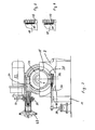
- Fig. 1 die Seitenansicht einer mit der erfindungsgemäßen Vorrichtung ausgestatteten Fleischzerkleinerungsmaschine,
- Fig. 2 einen Schnitt gemäß der Linie 2-2,
- Fig. 3 einen Ausschnitt aus der Fig. 1 in vergrößertem Maßstab mit angestellten Messerklingen und
- Fig. 4 eine der Fig. 3 entsprechende Darstellung mit abgehobenen Messerklingen.
- 1 is a side view of a meat chopping machine equipped with the device according to the invention,
- 2 shows a section along the line 2-2,
- Fig. 3 shows a detail of FIG. 1 on an enlarged scale with knife blades and
- FIG. 4 shows a representation corresponding to FIG. 3 with the knife blades raised.
Die in der Fig. 1 in der Seitenansicht dargestellte Fleischzerkleinerungsmaschine weist einen Sokkel 1 auf, auf dem ein mit 2 bezeichnetes Maschinengehäuse aufsitzt. An diesem Maschinengehäuse 2 ist ein Lagergehäuse 3 angeformt, das der Aufnahme und Lagerung einer mit 4 bezeichneten Antriebswelle dient, die über eine elastische Kupplung 5 von einem Elektromotor 6 in Umlauf versetzt wird. An der dem Elektromotor 6 abgekehrten Seite des Maschinengehäuses 2 ist ferner ein einen Trichter 7 aufweisendes Einlaufgehäuse 8 angeformt, an dessen dem Elektromotor 6 abgekehrten Seite ein mit 9 bezeichneter Schneidkopf angeordnet ist, in den das mit 10 bezeichnete Ende der Antriebswelle 4 hineinragt. Dieser Schneidkopf 9 ist dabei durch ein Auslaufgehäuse 11 abgedeckt, dessen Auswurföffnung mit 12 bezeichnet ist.The meat shredder shown in side view in FIG. 1 has a
In dem Schneidkopf 9 sind in axialer Richtung hintereinander zwei Lochplatten 13 und 14feststehend angeorndet und mittels einer Ringfassung 15, eines Staufingerringes 16 und eines zwischen den beiden Lochplatten 13 und 14 befindlichen Stützringes 17 fixiert. Diesen beiden Lochplatten 13 und 14 sind mit 18 und 19 bezeichnete Messerköpfe zugeordnet, die jeweils mit mehreren Messerklingen 20 ausgerüstet sind. Diese beiden Messerköpfe 18 und 19 sind dabei auf dem freien Ende 10 derAntriebswelle 4 aufgeschoben und arretiert. Der diesem wellensende 10 benachbarte, durch das Einlaufgehäuse 8 hindurchgreifende Wellenteil 21 ist dabei durch eine zusammen mit der Antriebswelle 4 umlaufende Hülse 22 abgedeckt.In the
Wie weiter aus der Fig. 1 ersichtlich ist, so dient das Maschinengehäuse 2 der Lagerung einer feststehenden Lagerbuchse 23, in.deren Innengewinde 24 eine ein Außengewinde 25 aufweisende drehbare Gewindehülse 26 teilweise eingeschraubt ist. Der über diese feststehende Lagerbuchse 23 hinausragende Teil 27 dieser Gewindehülse 26 ist dabei zylindrisch ausgestaltet und stützt sich über einen mit 28 bezeichneten Ringdeckel an dem Mantel der Antriebswelle 4 ab, deren Wellenteil 29 mittels Kugellager 30 in der Gewindehülse 26 gelagert ist.As can also be seen from FIG. 1, the
An der dem Büchsenteil 27 abgekehrten Stirnseite dieser Gewindebuchse 26 ist ein mit 31 bezeichnetes Schneckenrad befestigt, in die eine von einem Stellmotor 32 über Kettenräder 33 in Umlauf versetzte Schneckenwelle 34 eingreift.On the end face of the threaded
Wie sich weiter aus den beiden Fign. 1 und 2 ergibt, so greift um den zylindrischen Buchsenteil 27 ein zu einer Spanneinrichtung gehöriger Spannring 35 satt herum, der mittels eines mit 36 bezeichneten Spannbolzens sowie einer zu diesem gehörigen Spannmutter 37 zu spannen und zu lösen ist. Das Spannen und Lösen dieses Spannringes 35 erfolgt dabei mittels eines pneumatischen Zylinders 38, dessen Kolbenstange 39 an einer mit 40 bezeichneten Kurbel angelenkt ist, der bei einem Hub der Kolbenstange 39 eine Schwenkbewegung in Richtung des Pfeiles 41 erteilt wird. Je nach der jeweiligen Drehrichtung erfolgt dabei ein Anziehen oder ein Lösen der Spannmutter 37, was wieder ein entsprechendes Spannen oder Lösen des Spannringes 35 zur Folge hat.As can further be seen from the two FIGS. 1 and 2 results in a
Der Arbeitsablauf bei dieser erfindungsgemäßen Fleischzerkleinerungsmaschine ist der folgende: Bei der in der Fig. 1 dargestellten Arbeitsstellung der Antriebswelle 4 sowie auch der auf dieser angeordneten Messerköpfe 18 und 19 nimmt die Kolbenstange 39 ihre ausgezogen dargestellte Ruhestellung ein, in der die Spannmutter 37 angezogen und der Spannring 35 gespannt sind. Dieser Spannring 35 umfaßt dabei satt den zylindrischen Büchsenteil 27, so daß ein Verdrehen der Gewindehülse 26 nicht möglich ist. Damit aber ist die Antriebswelle 4 gegen jede axiale Verschiebung gesichert. In dieser Arbeitsstellung der Antriebswelle 4 wird das Schneidgut in Richtung des Pfeiles 42 in den Trichter 7 eingeführt, von dem es in Richtung der Pfeile 43 zu den Messerköpfen 18 und 19 und den zugehörigen Lochplatten 13 und 14 gelangt, um nach dem Schneidvorgang in Richtung des Pfeiles 44 durch die in dem Auslaufgehäuse 11 befindliche Auswurföffnung 12 auszutreten.The workflow in this meat chopping machine according to the invention is as follows: In the working position of the
Wird nun die weitere Zugabe von Schneidgut in Richtung des Pfeiles 42 eingestellt, so sinkt die Belastung des Elektromotors 6 ab. Nach Unterschreiten einer Mindestbelastung wird über eine elektronische Steuerung der Kolbenstange 39 ein Hub in Richtung des Pfeiles 45 und damit der Kurbel 40 eine Schwenkbewegung in Richtung des Pfeiles 41 erteilt, was ein Lösen der Spannmutter 37 und damit auch des Spannringes 35 sowie eine Freigabe der Gewindehülse 26 zur Folge hat. Über die elektronische Steuereinrichtung wird anschließend der Stellmotor 32 in Drehung versetzt, der über die Schneckenwelle 34 und das Schneckenrad 31 eine Drehung der Gewindehülse 26 und damit eine axiale Verschiebung derselben gegenüber der feststehenden Lagerbuchse 23 bewirkt. Infolge dieser Verschiebung der Gewindehülse 26 in Richtung des Pfeiles 46 wird auch die Antriebswelle 4 zusammen mit den beiden Messerköpfen 18 und 19 zurückgezogen, was ein Abheben der Messerklingen 20 von den Schneidflächen der gegenüberstehenden Lochplatten 13 bzw. 14 in der in der Fig. 4 dargestellten Weise zur Folge hat. Ist diese axiale Verschiebung der Antriebswelle 4 beendet, so kehrt die Kolbenstange 39 wieder in ihre Ruhestellung zurück, wodurch der Spannring 35 wieder gespannt und damit die Gewindehülse 26 und mit dieser auch die Antriebswelle 4 arretiert werden.If the further addition of material to be cut is now set in the direction of arrow 42, the load on the
Wird, nachdem die Fleischzerkleinerungsmaschine eine kürzere oder längere Zeit im Leerlauf gefahren worden ist, ergeut Schneidgut in Richtung des Pfeiles 42 in den Trichter 7 gegeben, so steigt die Belastung des Elektromotors 6 wieder an. Sobal die vorgegebenen Minimalbelastung des Elektromotors 6 überschritten ist, bewirkt die elektronische Steuerung wieder ein Lösen des Spannringes 35 sowie ein Verdrehen der Gewindehülse 26, was nunmehr ein Vorschieben der Antriebswelle 4 und der auf derselben sitzenden Messerköpfe 18 und 19 entgegen der Richtung des Pfeiles 46 zur Folge hat. Die Messerklingen 20 der beiden Messerköpfe 18 und 19 nehmen somit wieder ihre in der Fig. 3 dargestellte Arbeitsstellung ein, in der ihre Schneiden satt an den Schneidflächen der beiden zugehörigen Lochplatten 13 und 14 anliegen. Nachdem die Kolbenstange 39 wieder in ihre Ruhestellung zurückgekehrt ist, ist auch der Spannring 35 wieder gespannt, so daß sowohl die Gewindehülses 26 als auch die Antriebswelle 4 mit den beiden Messerköpfen 18 und 19 gegen jede weitere axiale Verschiebung gesichert sind.If, after the meat chopping machine has been idling for a shorter or longer time, cut material is put into the
Um nach einem eventuellen Schleifen der zu den Messerköpfen 18 und 19 gehörigen Messerklingen 20 diese gegenüber den Schneidflächen der benachbarten Lochplatten 13 und 14 sicher und gefühlvoll einstellen zu können, ist der Schneckenwelle 34 noch ein mit 47 bezeichnetes Handrad zugeordnet, mittels dem unabhängig von dem Stellmotor 32 die Antriebswelle und mit dieser die beiden Messerköpfe manuell axial verschoben werden können.In order to be able to safely and sensitively adjust the
Claims (6)
Priority Applications (1)
| Application Number | Priority Date | Filing Date | Title |
|---|---|---|---|
| AT87108228T ATE56893T1 (en) | 1986-06-19 | 1987-06-06 | DEVICE FOR AUTOMATIC ADJUSTMENT OF THE BLADE SET OF A MEAT MINCING MACHINE. |
Applications Claiming Priority (2)
| Application Number | Priority Date | Filing Date | Title |
|---|---|---|---|
| DE3620598A DE3620598C2 (en) | 1986-06-19 | 1986-06-19 | Device for automatically adjusting the cutting set of a meat chopping machine |
| DE3620598 | 1986-06-19 |
Publications (3)
| Publication Number | Publication Date |
|---|---|
| EP0249840A2 EP0249840A2 (en) | 1987-12-23 |
| EP0249840A3 EP0249840A3 (en) | 1988-11-30 |
| EP0249840B1 true EP0249840B1 (en) | 1990-09-26 |
Family
ID=6303289
Family Applications (1)
| Application Number | Title | Priority Date | Filing Date |
|---|---|---|---|
| EP87108228A Expired - Lifetime EP0249840B1 (en) | 1986-06-19 | 1987-06-06 | Device for automatically adjusting the knives of a meat-mincing machine |
Country Status (10)
| Country | Link |
|---|---|
| US (1) | US4775108A (en) |
| EP (1) | EP0249840B1 (en) |
| JP (1) | JPS6323757A (en) |
| AT (1) | ATE56893T1 (en) |
| CA (1) | CA1298534C (en) |
| DE (1) | DE3620598C2 (en) |
| DK (1) | DK167855B1 (en) |
| ES (1) | ES2017671B3 (en) |
| FI (1) | FI87619C (en) |
| NO (1) | NO171402C (en) |
Families Citing this family (11)
| Publication number | Priority date | Publication date | Assignee | Title |
|---|---|---|---|---|
| DE3921109C2 (en) * | 1989-06-28 | 1999-06-17 | Schnell Maschfab Karl | Shredding machine |
| DE3931813A1 (en) * | 1989-09-23 | 1991-04-04 | Schnell Maschfab Karl | CUTTING SET FOR A CRUSHING MACHINE |
| DE8911353U1 (en) * | 1989-09-23 | 1989-11-02 | Karl Schnell GmbH & Co Maschinenfabrik, 7065 Winterbach | Chopping machine, especially for meat etc. |
| JPH0784010B2 (en) * | 1991-11-29 | 1995-09-13 | 株式会社神戸製鋼所 | Underwater cutting granulator |
| DE9206333U1 (en) * | 1992-05-12 | 1992-08-27 | Karl Schnell GmbH & Co Maschinenfabrik, 7065 Winterbach | Cutting set of a fine grinding machine for doughy masses |
| DE4420693C2 (en) * | 1994-06-14 | 1996-06-05 | Inofex Gmbh | Clamping and adjusting device for cutting sets in meat grinders |
| US5699970A (en) * | 1996-07-11 | 1997-12-23 | 2 M Tool Co., Inc. | Meat-comminuting machine with improved vacuum discharge mechanism |
| DE29622298U1 (en) * | 1996-12-21 | 1998-04-16 | Tetra Laval Convenience Food | meat grinder |
| DE19960409A1 (en) * | 1999-12-15 | 2001-06-21 | Inotec Gmbh Maschinenentwicklu | Device for comminuting a material to be comminuted |
| DE102014216720A1 (en) | 2014-08-22 | 2016-02-25 | Karl Schnell Gmbh & Co. Kg | Crushing machine for crushing a product |
| CA2970426C (en) * | 2014-12-15 | 2023-05-16 | Human Brain Wave S.R.L. | Disgregating device of biological material and corresponding manufacturing method and method for the preparation of cell suspensions and tissue micrografts |
Family Cites Families (8)
| Publication number | Priority date | Publication date | Assignee | Title |
|---|---|---|---|---|
| US10717A (en) * | 1854-03-28 | Pateet | ||
| AT207720B (en) * | 1958-05-24 | 1960-02-25 | Erich Hoertnagl | Device for crushing animal products |
| DE1159803B (en) * | 1960-03-09 | 1963-12-19 | Carl Schnell Maschinenfabrik | Shredding machine for meat, bread, etc. like |
| DE1117438B (en) * | 1960-03-26 | 1961-11-16 | Carl Schnell Maschinenfabrik | Chopping machine for meat, bread or the like. |
| DE1657220B2 (en) * | 1968-03-01 | 1976-08-12 | Vemag Verdener Maschinen- Und Apparatebau Gmbh, 3090 Verden | MEAT CUTTER |
| US3610541A (en) * | 1969-10-29 | 1971-10-05 | Beloit Corp | Apparatus for controlling paper stock refiners |
| JPS5646966B2 (en) * | 1974-01-08 | 1981-11-06 | ||
| EG13919A (en) * | 1979-01-23 | 1983-03-31 | Satake Eng Co Ltd | Automatic control system for hilling machine |
-
1986
- 1986-06-19 DE DE3620598A patent/DE3620598C2/en not_active Expired - Fee Related
-
1987
- 1987-06-06 AT AT87108228T patent/ATE56893T1/en not_active IP Right Cessation
- 1987-06-06 EP EP87108228A patent/EP0249840B1/en not_active Expired - Lifetime
- 1987-06-06 ES ES87108228T patent/ES2017671B3/en not_active Expired - Lifetime
- 1987-06-12 US US07/062,175 patent/US4775108A/en not_active Expired - Fee Related
- 1987-06-17 FI FI872710A patent/FI87619C/en not_active IP Right Cessation
- 1987-06-18 NO NO872561A patent/NO171402C/en unknown
- 1987-06-18 CA CA000539965A patent/CA1298534C/en not_active Expired - Fee Related
- 1987-06-18 DK DK310487A patent/DK167855B1/en not_active IP Right Cessation
- 1987-06-19 JP JP62151568A patent/JPS6323757A/en active Pending
Also Published As
| Publication number | Publication date |
|---|---|
| FI87619B (en) | 1992-10-30 |
| ATE56893T1 (en) | 1990-10-15 |
| DE3620598A1 (en) | 1987-12-23 |
| FI87619C (en) | 1993-02-10 |
| EP0249840A3 (en) | 1988-11-30 |
| FI872710A7 (en) | 1987-12-20 |
| NO171402B (en) | 1992-11-30 |
| DK310487A (en) | 1987-12-20 |
| NO171402C (en) | 1993-03-10 |
| ES2017671B3 (en) | 1991-03-01 |
| NO872561L (en) | 1987-12-21 |
| DK310487D0 (en) | 1987-06-18 |
| EP0249840A2 (en) | 1987-12-23 |
| DK167855B1 (en) | 1993-12-27 |
| FI872710A0 (en) | 1987-06-17 |
| DE3620598C2 (en) | 1997-08-14 |
| CA1298534C (en) | 1992-04-07 |
| NO872561D0 (en) | 1987-06-18 |
| US4775108A (en) | 1988-10-04 |
| JPS6323757A (en) | 1988-02-01 |
Similar Documents
| Publication | Publication Date | Title |
|---|---|---|
| EP0249840B1 (en) | Device for automatically adjusting the knives of a meat-mincing machine | |
| EP2386200A1 (en) | Self-propelled chaff cutter | |
| DE2256267C3 (en) | Shredder working with shear action | |
| EP1286811B1 (en) | Arrangement for pressing the blades towards the perforated plate of a granulating device | |
| EP0687503A1 (en) | Roll Shredder | |
| DE19508093A1 (en) | Heavy duty food mincing machine | |
| DE3939213C2 (en) | ||
| DD275361A3 (en) | MEAT GRINDER | |
| DE3535902C2 (en) | ||
| EP1371420B1 (en) | Comminuting apparatus for reducing a material | |
| WO1997005953A1 (en) | Mincing machine | |
| EP0574694B1 (en) | Cutting tool for a machine for comminution of pasty substances | |
| WO2004089588A1 (en) | Drive unit for a granulator | |
| EP1196244B1 (en) | Machine for chopping organic cut products | |
| DE1117438B (en) | Chopping machine for meat, bread or the like. | |
| CH415334A (en) | Shredding machine for meat or other food and luxury foods that can be shredded | |
| DE3908395A1 (en) | Device for disintegrating leftover and waste wood | |
| DE1030218B (en) | Shredder for meat and similar products | |
| DE930560C (en) | Grinding device for rotating circular knife discs of cutting machines, especially tobacco cutting machines | |
| AT222532B (en) | Chopping machine for meat, bread or the like. | |
| EP1002583A2 (en) | Material treating machine with stator adjustment | |
| DE1181091B (en) | Wolf for chopping meat and other foods | |
| DE3036490A1 (en) | GRINDING DEVICE FOR AGRICULTURAL DISC WHEEL CUTTING MACHINE | |
| WO2010115484A1 (en) | Grinder, particularly coarse material grinder | |
| DE2209323A1 (en) | Device for sharpening the knife of a guillotine-like cutting device |
Legal Events
| Date | Code | Title | Description |
|---|---|---|---|
| PUAI | Public reference made under article 153(3) epc to a published international application that has entered the european phase |
Free format text: ORIGINAL CODE: 0009012 |
|
| AK | Designated contracting states |
Kind code of ref document: A2 Designated state(s): AT BE CH ES FR GB IT LI NL SE |
|
| PUAL | Search report despatched |
Free format text: ORIGINAL CODE: 0009013 |
|
| AK | Designated contracting states |
Kind code of ref document: A3 Designated state(s): AT BE CH ES FR GB IT LI NL SE |
|
| 17P | Request for examination filed |
Effective date: 19881028 |
|
| 17Q | First examination report despatched |
Effective date: 19890906 |
|
| GRAA | (expected) grant |
Free format text: ORIGINAL CODE: 0009210 |
|
| AK | Designated contracting states |
Kind code of ref document: B1 Designated state(s): AT BE CH ES FR GB IT LI NL SE |
|
| REF | Corresponds to: |
Ref document number: 56893 Country of ref document: AT Date of ref document: 19901015 Kind code of ref document: T |
|
| ET | Fr: translation filed | ||
| ITF | It: translation for a ep patent filed | ||
| GBT | Gb: translation of ep patent filed (gb section 77(6)(a)/1977) | ||
| ITTA | It: last paid annual fee | ||
| PLBE | No opposition filed within time limit |
Free format text: ORIGINAL CODE: 0009261 |
|
| STAA | Information on the status of an ep patent application or granted ep patent |
Free format text: STATUS: NO OPPOSITION FILED WITHIN TIME LIMIT |
|
| 26N | No opposition filed | ||
| PGFP | Annual fee paid to national office [announced via postgrant information from national office to epo] |
Ref country code: BE Payment date: 19920609 Year of fee payment: 6 |
|
| PGFP | Annual fee paid to national office [announced via postgrant information from national office to epo] |
Ref country code: SE Payment date: 19920623 Year of fee payment: 6 |
|
| PGFP | Annual fee paid to national office [announced via postgrant information from national office to epo] |
Ref country code: FR Payment date: 19930514 Year of fee payment: 7 |
|
| PGFP | Annual fee paid to national office [announced via postgrant information from national office to epo] |
Ref country code: CH Payment date: 19930517 Year of fee payment: 7 |
|
| PGFP | Annual fee paid to national office [announced via postgrant information from national office to epo] |
Ref country code: GB Payment date: 19930518 Year of fee payment: 7 |
|
| PGFP | Annual fee paid to national office [announced via postgrant information from national office to epo] |
Ref country code: AT Payment date: 19930521 Year of fee payment: 7 |
|
| PG25 | Lapsed in a contracting state [announced via postgrant information from national office to epo] |
Ref country code: SE Effective date: 19930607 |
|
| PG25 | Lapsed in a contracting state [announced via postgrant information from national office to epo] |
Ref country code: BE Effective date: 19930630 |
|
| PGFP | Annual fee paid to national office [announced via postgrant information from national office to epo] |
Ref country code: NL Payment date: 19930630 Year of fee payment: 7 |
|
| BERE | Be: lapsed |
Owner name: KARL SCHNELL G.M.B.H. & CO. MASCHINENFABRIK Effective date: 19930630 |
|
| PG25 | Lapsed in a contracting state [announced via postgrant information from national office to epo] |
Ref country code: GB Effective date: 19940606 Ref country code: AT Effective date: 19940606 |
|
| PGFP | Annual fee paid to national office [announced via postgrant information from national office to epo] |
Ref country code: ES Payment date: 19940610 Year of fee payment: 8 |
|
| PG25 | Lapsed in a contracting state [announced via postgrant information from national office to epo] |
Ref country code: LI Effective date: 19940630 Ref country code: CH Effective date: 19940630 |
|
| PG25 | Lapsed in a contracting state [announced via postgrant information from national office to epo] |
Ref country code: NL Effective date: 19950101 |
|
| EUG | Se: european patent has lapsed |
Ref document number: 87108228.5 Effective date: 19940110 |
|
| GBPC | Gb: european patent ceased through non-payment of renewal fee |
Effective date: 19940606 |
|
| NLV4 | Nl: lapsed or anulled due to non-payment of the annual fee | ||
| PG25 | Lapsed in a contracting state [announced via postgrant information from national office to epo] |
Ref country code: FR Effective date: 19950228 |
|
| REG | Reference to a national code |
Ref country code: CH Ref legal event code: PL |
|
| REG | Reference to a national code |
Ref country code: FR Ref legal event code: ST |
|
| PG25 | Lapsed in a contracting state [announced via postgrant information from national office to epo] |
Ref country code: ES Free format text: LAPSE BECAUSE OF EXPIRATION OF PROTECTION Effective date: 19950607 |
|
| REG | Reference to a national code |
Ref country code: ES Ref legal event code: FD2A Effective date: 19990601 |
|
| PG25 | Lapsed in a contracting state [announced via postgrant information from national office to epo] |
Ref country code: IT Free format text: LAPSE BECAUSE OF NON-PAYMENT OF DUE FEES;WARNING: LAPSES OF ITALIAN PATENTS WITH EFFECTIVE DATE BEFORE 2007 MAY HAVE OCCURRED AT ANY TIME BEFORE 2007. THE CORRECT EFFECTIVE DATE MAY BE DIFFERENT FROM THE ONE RECORDED. Effective date: 20050606 |