EP0249788B1 - Einrichtung an Druckmaschinen mit Stelleinrichtungen für Umfangs-, Seiten- und Diagonalregister - Google Patents
Einrichtung an Druckmaschinen mit Stelleinrichtungen für Umfangs-, Seiten- und Diagonalregister Download PDFInfo
- Publication number
- EP0249788B1 EP0249788B1 EP87107861A EP87107861A EP0249788B1 EP 0249788 B1 EP0249788 B1 EP 0249788B1 EP 87107861 A EP87107861 A EP 87107861A EP 87107861 A EP87107861 A EP 87107861A EP 0249788 B1 EP0249788 B1 EP 0249788B1
- Authority
- EP
- European Patent Office
- Prior art keywords
- register
- light
- plate cylinder
- printing
- input
- Prior art date
- Legal status (The legal status is an assumption and is not a legal conclusion. Google has not performed a legal analysis and makes no representation as to the accuracy of the status listed.)
- Expired - Lifetime
Links
- 238000011156 evaluation Methods 0.000 claims description 11
- 238000005286 illumination Methods 0.000 claims description 6
- 238000001514 detection method Methods 0.000 claims description 4
- 230000002093 peripheral effect Effects 0.000 claims 5
- 238000009792 diffusion process Methods 0.000 claims 1
- 238000005070 sampling Methods 0.000 claims 1
- 238000000926 separation method Methods 0.000 claims 1
- 238000005259 measurement Methods 0.000 abstract description 12
- 238000010835 comparative analysis Methods 0.000 abstract 1
- 230000007246 mechanism Effects 0.000 abstract 1
- 230000015654 memory Effects 0.000 description 26
- 230000001960 triggered effect Effects 0.000 description 9
- 238000010586 diagram Methods 0.000 description 7
- 230000006870 function Effects 0.000 description 4
- 230000003111 delayed effect Effects 0.000 description 3
- 238000006243 chemical reaction Methods 0.000 description 2
- 238000012937 correction Methods 0.000 description 2
- 238000000034 method Methods 0.000 description 2
- 230000003287 optical effect Effects 0.000 description 2
- 230000011514 reflex Effects 0.000 description 2
- 230000000630 rising effect Effects 0.000 description 2
- 238000012546 transfer Methods 0.000 description 2
- 230000003321 amplification Effects 0.000 description 1
- 230000001934 delay Effects 0.000 description 1
- 238000011161 development Methods 0.000 description 1
- 230000018109 developmental process Effects 0.000 description 1
- 238000003384 imaging method Methods 0.000 description 1
- 238000003199 nucleic acid amplification method Methods 0.000 description 1
- 230000002441 reversible effect Effects 0.000 description 1
- 239000004065 semiconductor Substances 0.000 description 1
- 238000011144 upstream manufacturing Methods 0.000 description 1
Images

Classifications
-
- B—PERFORMING OPERATIONS; TRANSPORTING
- B41—PRINTING; LINING MACHINES; TYPEWRITERS; STAMPS
- B41F—PRINTING MACHINES OR PRESSES
- B41F13/00—Common details of rotary presses or machines
- B41F13/08—Cylinders
- B41F13/10—Forme cylinders
- B41F13/12—Registering devices
-
- B—PERFORMING OPERATIONS; TRANSPORTING
- B41—PRINTING; LINING MACHINES; TYPEWRITERS; STAMPS
- B41F—PRINTING MACHINES OR PRESSES
- B41F33/00—Indicating, counting, warning, control or safety devices
- B41F33/0081—Devices for scanning register marks
Definitions
- the invention relates to a device on printing machines according to the preamble of the first claim.
- Devices of this type are already known from a number of publications, e.g. from DE-PS 3 136 703, DE-OS 3 136 704, DE-OS 3 302 200, DE-OS 3 535 579 and JP-PS 55-25062 / 1980.
- the devices mentioned have a registration mark detection device on each plate cylinder, which emits a measurement signal which is generated by reflective markings, e.g. line marks in the form of register crosses or punched-out areas on the printing plates are scanned by means of reflex scanning systems or the like.
- the accuracy of the evaluation strongly depends on the quality of the edges and the contrast, because the reflective markings are scanned as shadows in a bright environment of a light receiver.
- the object of the invention is, in a device of the type mentioned, to reflective line marks, i.e. the evaluation of a shadow in the bright environment of a light receiver and to enable an evaluation of a light spot in a darkened environment of a light receiver that is independent of the contrast and the edge quality.
- the advantages of the invention are that light marks of constant brightness are scanned, which results in signals constant amplitude. With homogeneous light marks, the edge zone influence is minimal compared to the full surface. Therefore, a higher scanning accuracy can be achieved with the same effort than when scanning reflective markings.
- the light projected directly onto the light receiver leads to a large electrical useful signal with a high signal-to-noise ratio and simplifies signal evaluation.
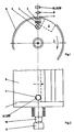
- each plate cylinder 1 having channel 2 on the drive side and on the operating side is either opposite one another or only on one side in succession or side by side outside the printing area and inking area for illuminating the correspondingly arranged, precisely fitting openings 7 with lighting devices, consisting of a light source 5, an illumination optics 4 and a diffuser 3.
- the precisely fitting openings 7 preferably have the shape of a circular punched punch, which appears as a light mark. However, oval shapes, rectangular, square or triangular shapes are also suitable.
- This light mark which is generated synchronously with the rotation of the plate cylinder 1, is projected through a fixedly mounted optical system 8 in the optimal scale onto a machine-mounted digitally position-sensitive line photosensor 12 in the dark environment when the preferably circular punched hole (7) runs through it.
- a current transformer 10 and a pulse generator 11 At the end of the axis of the plate cylinder 1 there is a current transformer 10 and a pulse generator 11 with an additional trigger pulse.
- the optics 8 serve to adapt the geometry of the precisely fitting opening 7 to the dimensions of suitable commercially available light receivers having a large number of photosensitive elements.
- the light marks formed by the precisely fitting openings 7 are adapted to the grid of the light receivers in an optimal, finely graded gradation.
- the following display can already be adapted to a common scaling during the measurement.
- a line photosensor has line-shaped photosensitive areas with e.g. well over 1,000 photosensitive elements, also known as CCD line imaging IC.
- Illumination device 3, 4, 5 and line photo sensor 12 with upstream optics 8 can change their opposite position, so that each light transmitter or light receiver arranged in a breakthrough in the jacket of the plate cylinder rotate with the plate cylinder 1, while the non-rotating assembly is arranged in a machine-fixed manner.
- the measuring points of the individual plate cylinders 1 pass through the sensors assigned to them in a machine-related, special machine position. Deviations after plus or minus are a measure of the registration error. Using the remote register adjustment, all plate cylinders 1 can be set to "zero" or a zero deviation that is the same for all plate cylinders 1.
- the pulse generator 11 delivers counting pulses which are evenly distributed over the circumference and which are passed via a gate circuit 15 to a counter 16 and a preselection counter 33.
- the pulse generator 11 delivers a single pulse per revolution, hereinafter referred to as a zero pulse. This is e.g. mechanically adjusted so that it is triggered at a time when the nominal start of pressure of the plate cylinder 1 to be adjusted passes the position of the line photo sensor 12. Other reference points of the measurement are also possible.
- the leading edge of the zero pulse is generated in a pulse shaper 32 (FIG. 5) to form a signal of a short duration that is independent of the machine speed. It resets the counter 16 and the preselection counter 33 to the zero position and an electronic switch 34 to the basic position.
- a new measuring cycle is now prepared. This starts when a timer 14, controlled by the zero pulse, opens the gate circuit 15 with a signal with a slight offset in time and switches a memory 24 to "ready for storage". The counting pulses thus arrive from the pulse generator 11, the counter 16 and the preselection counter 33 in order to be added up there.
- the gate circuit 15 is closed by a signal triggered by a peak level indicator 50. This is prepared when the input signal, starting from an OR link 25, has exceeded the set level of a threshold switch 50A (FIG. 6). The signal which is still rising is now also fed to a peak value memory 50B, which stores the still rising maximum level with a low loss rate and applies the stored signal to an input of a compensator 50C. At the second input of the compensator 50C is the level emanating from the OR link 25. This level is only reduced when the line photo sensor 12 receives slightly less light through the rotating, precisely fitting opening 7. As a result of the voltage difference then present at the inputs of the compensator 50C, the pulse emanating from the assembly 50 (FIG. 6) is triggered and closes the gate circuit 15.
- the counter reading obtained in this way is a measure of the path that the circumference of the plate cylinder 1 has covered the specified setting from the nominal start of pressure to the precisely fitting opening 7.
- the peak level indicator 50 is actuated by the line photo sensor 12 when the precisely fitting opening 7 illuminated by the light source 5 is moved past.
- the interposed OR link 25 connects the individual sensors of the line photo sensor 12 to the common input at the peak level indicator 50.
- the individual elements themselves are controlled and forwarded with digital signals via a clock generator 17 and clock 27. These signals are also fed to the memory 24, which was switched to readiness for takeover by the output signal of the timing element 14.
- the store command is provided by an AND link 35 if the electronic switch 34 was previously reset by the zero pulse and activates one input, while the second input from the peak level indicator 50 is controlled.
- the position of that individual sensor of the line photo sensor 12 which has responded to the rotating, illuminated, precisely fitting opening 7 is thus stored in the memory 24.
- This position is fed to a display 19 and a comparator 30 or the like - if necessary via a code converter 26 - and is displayed or compared with a target value. Differences between the setpoint and actual value serve, interruptable by an automatic off switch 48, in an output circuit 31 to form the control signals for the axial adjustment 58, 59 of the plate cylinder 1 to the left or right.
- the target value for the printing unit to be controlled is entered by means of a target value setting 28 and fed to the comparator 30 via a reference variable selector switch 29.
- the command variable selector switch 29 also allows the command variable to be specified for another printing unit and thus to drive the machine to the same page register.
- the status of the counter 16 is activated, if necessary, via a code converter 18, a display 9 and the comparator 22.
- the takeover into the memory of the display 9, as well as the display 19, is triggered by a timer 54 with a slight delay due to the output of the peak level indicator 50.
- the functions of setpoint adjustment 20, reference variable selector switch 21, comparator 22 and automatic off switch 47 correspond to those of function groups 28, 29, 30 and 48 for the lateral adjustment.
- the output circuit 23 supplies signals which move the plate cylinder 1 back and forth in the circumferential direction 56, 57 relative to the drive.
- the presetting of the preselection counter 33 is expediently to be selected such that the coincidence between this and the counter reading occurs when the second, precisely fitting opening 7, which is laterally offset from the first in is located behind the printing plate area and is illuminated by the light source 5B, just before the line photosensor 12.
- the output of the preselection counter 33 sets the electronic changeover switch 34, which as a result switches its output signal from the AND link 35 to an AND link 40 and activates a memory 41 which receives the same position information of the line photo sensor 12 as the memory 24.
- an output pulse of the peak level indicator 50 is now triggered at the AND link 40 that the position information present at the memory 41 is taken over and stored and, if necessary via a code converter 42, leads to a display 44 and a comparator 43.
- An output circuit 45 that can be separated with the automatic-off switch 49 controls the drive of the cylinder inclined position 60, 61 back and forth.
- the automatic cylinder inclination is only activated via an OR link 46 if none of the output circuits 23 and 31 still emit control signals.
- the transfer into the memory of the display 44 is slightly delayed by a timer 55, triggered by the memory signal of the AND link 40.
- the block diagram for the other printing units of a printing press is identical to the above, but with the restriction that further pulse generators 11 can be dispensed with if, according to FIG. 5, a preselection counter 51 to 53 is used for a four-color press for each additional printing unit.
- the number of preselection steps is to be selected so that the signal triggering of the preselection counter takes place when the nominal start of pressure of the plate cylinder 1 to be controlled in each case passes the position of the respective line photo sensor 12.
- the pulse formers 32 of the respective printing unit controls are activated.
- the individual printing units in the components for example 21, 22, 29 and 30, are indicated by arrows.
- the second lateral measurement for the cylinder inclined position provided according to the exemplary embodiment described above is omitted if precisely fitting openings 7 arranged on both sides of the cylinder should be scanned.
- the modules 9, 12, 15, 16, 22, 23, 25 and 50 are then required for the measurement on the opposite side of the pressure plate 6. This means that in this case the pulse shaper 32, the timing element 14, the clock generator 17 with clock 27, the target value setting 20 and the reference variable selector switch 21 can be used together for the cylinder inclination measurement.
- position detectors 13 instead of the line photo sensors 12.
- a position detector works like a potentiometer, to which a current is fed via the tap contact. It is divided into two streams to the end contacts. The difference in the currents corresponds to the position of the tap contact, continuously and with high resolution.
- Position detectors are commercially available in various sizes and housings as single-axis and two-axis position detectors. According to FIG. 7, at the end of the axis of the plate cylinder 1 there are the current transmitter 10 and a pulse generator 11 for generating two trigger pulses 11A and 11B which are independent of one another and can be adjusted to any cylinder angle in the format range.
- the pulse generator 11A is set so that when the plate cylinder 1 is in the zero position for the cylinder drive and in the center position for the pressure cylinder, a trigger signal is triggered when the center of the plate cylinder 1 rotating light source 5A is radially opposite the standing position detector 13.
- the precisely fitting opening 7 is provided in the printing form 6 in the area of the start of the print so that it is also in the center of the lighting device 3, 4, 5 when the plate is optimally mounted.
- the A / D converter 37 in the sample state is switched to "hold” with the pulse generator 11A at the same time as an A / D converter 38 and sends its digitized signal to a memory 39, which delays the takeover signal slightly via the timing element 62 receives.
- the position of the precisely fitting opening 7 stored in the memory 39 is indicated on the circumference with the display 9.
- the corresponding register adjustment can be carried out manually by adjusting the cylinder for the drive in a known manner.
- the content of the memory 39 is also passed to a reference variable selection switch 21, the reference variable selection switches (not shown) of the further printing units of the printing press and to the comparator 22.
- the reference variable selector switch 21 By means of the reference variable selector switch 21, either the actual value of each printing unit or a signal level which is the same for all printing units and is generated by the reference signal generator 63 and which suitably corresponds to the basic printing plate setting can be specified.
- the setpoint / actual value comparison produces a signal which can be interrupted by the automatic off switch 47 and which in the output circuit 23 gives corrective control pulses to the circumferential adjustment of the plate cylinder 1 in accordance with the measured plate circumferential position which deviates from the nominal value.
- the A / D converter with sample and hold 38, the memory 66, the display 19, the reference variable selection switch 29, the comparator 30, the automatic off switch 48 and the output circuit 31 the measurement and display of the lateral plate positions and, if necessary, the lateral cylinder adjustment are carried out in the same way as described above.
- the A / D converters 37 and 38 are reset to the sample function with a slight delay via the timing element 71 and thus for a new conversion prepared.
- the second registration punch is laterally offset in the circumferential direction at the end of the plate format outside the inking area (see FIG. 3).
- the second lighting device 3, 4, 5 with the light source 5B is also located in the plate cylinder 1.
- the pulse generator 11B is set in such a way that the signal is triggered at the point in time at which the center of the light source 5B, when the plate cylinder 1 is in the zero position for driving and its center position in relation to the printing cylinder, is radially opposite the standing position detector 13.
- An A / D converter with sample and hold 64 is thus switched to "hold” with the analog signal currently coming from amplifier 65 and the A / D conversion is carried out.
- the digitized signal is stored in the memory 68 and displayed by means of the display 44. Then, slightly delayed by the timer 69, the A / D converter 64 is reset to the sample function and thus prepared for the following measurement cycle.
- the comparator 43 receives its actual value from the memory 68, its setpoint, as does the comparator 30, from the reference variable selection switch 29 controls, can be switched off by the automatic off switch 49, the output circuit 45, which in turn switches on the inclined cylinder adjustment for register correction according to the measured values. This is blocked by an OR link 70 if an actuating signal is still emitted by one or both output circuits 23 and / or 31.
- the precisely fitting openings 7 and the corresponding lighting devices 3, 4, 5, the plate cylinder 1 can also be measured on both sides.
- a further, one-dimensional position detector 13 is necessary to form a two-dimensional position detector 13.
- An example with suitable locations of the punched punch is again shown in FIG. 3.
- the block diagram described above has to be modified in some points.
- the pulse generator 11B is omitted.
- an additional amplifier, not shown, is necessary, the signals of which are further processed via a corresponding assembly chain 43, 44, 45, 49, 64, 68. All A / D converters and memories are controlled in parallel by the pulse generator 11A and the downstream timing elements.
- the comparator 43 receives its reference variable from the reference variable selection switch 21. With the impluser 11B, the timing elements 67 and 69 are omitted.
- a position detector of a different type is the four-quadrant position detector 72 shown in FIG are separated. With it it can be determined on which of the four sectors the predominantly punctiform light mark 75 hits without precise location determination. This is only possible in the center because all four individual sensors 73 can be illuminated equally by a light mark 75 that strikes at this point and the sum of all output signals thus becomes zero.
- An evaluation circuit using the example of a circumferential measuring channel is shown in FIG. 8.
- the signals of the two diametrically opposed sectors of the four-quadrant position detector 72 are fed to the comparators 78 and 79 after amplification by the amplifiers 76 and 77.
- the comparator 79 is provided with a narrow tolerance field. Its output to the memory 80 determines whether and in which direction there is a registration error.
- the optical or acoustic displays 81 and 82 are activated or the control signals of the output circuit 84, which can be separated with the automatic off switch 83, are activated for adjusting the plate cylinder. They consist of pulses that become more intense when the comparator 78 has been driven by a larger input voltage difference.
- the output signals of the comparator 78 for pulse intensity control of the output circuit 84 and of the comparator 79 for triggering the directional pulses on the same output circuit are taken over when a pulse generator 85 is triggered with a trigger pulse.
- the trigger is set according to the procedure previously described.
- the circuit shown should also be used to adjust the sides and diagonal bends.
- one of the position detectors 72 can be replaced by a one-dimensional system, a duo sensor. With him, the measurement is made on the straight, isolated dividing line between the two, mostly right angle sensor elements.
- the movement of the actuator is stopped without a precise position determination having been necessary beforehand when the ratio of the illuminated sensor areas, which is detected by measuring the outputs a, a 'and b, b', is equal to 1 and the difference is equal Is 0.
- the output signals of the output circuit can have an electromechanical switch (relay or contactor) or an electronic switching device (e.g. semiconductor relay, thyristor, etc.) for switching a motor for clockwise or counterclockwise rotation, but also be used to switch on solenoid valves with hydraulic or pneumatic register adjustment.
- an electromechanical switch relay or contactor
- an electronic switching device e.g. semiconductor relay, thyristor, etc.
Landscapes
- Engineering & Computer Science (AREA)
- Mechanical Engineering (AREA)
- Inking, Control Or Cleaning Of Printing Machines (AREA)
- Rotary Presses (AREA)
- Length Measuring Devices By Optical Means (AREA)
- Registering Or Overturning Sheets (AREA)
- Automobile Manufacture Line, Endless Track Vehicle, Trailer (AREA)
- Body Structure For Vehicles (AREA)
- Printing Methods (AREA)
- Supply, Installation And Extraction Of Printed Sheets Or Plates (AREA)
Description
- Die Erfindung betrifft eine Einrichtung an Druckmaschinen nach dem Oberbegriff des ersten Patentanspruches.
- Einrichtungen genannter Gattung sind bereits aus einer Reihe von Veröffentlichungen bekannt, z.B. aus der DE-PS 3 136 703, der DE-OS 3 136 704, der DE-OS 3 302 200, der DE-OS 3 535 579 und der JP-PS 55-25062/1980.
- Die genannten Einrichtungen weisen eine Paßmarken-Erkennungseinrichtung bei jedem Plattenzylinder auf, die ein Meßsignal abgibt, das von reflektierenden Markierungen, z.B. von Strichmarken in Form von Paßkreuzen oder von Ausstanzungen an den Druckplatten mittels Reflex-Abtastsystemen o. dgl. abgetastet wird.
- Bei Abtastung im Reflexverfahren hängt aber die Genauigkeit der Auswertung stark von der Qualität der Kanten und vom Kontrast ab, weil die reflektierenden Markierungen als Schatten in einem hellen Umfeld eines Lichtempfängers abgetastet werden.
- Aufgabe der Erfindung ist es, bei einer Einrichtung genannter Gattung von der Auswertung reflektierender Strichmarken, d.h. der Auswertung eines Schattens im hellen Umfeld eines Lichtempfängers abzugehen und eine vom Kontrast und der Kantenqualität unabhängige Auswertung eines Lichtfleckes in einem abgedunkeltem Umfeld eines Lichtempfängers zu ermöglichen.
- Diese Aufgabe wird gemäß dem Kennzeichen des ersten Patentanspruches gelöst. Weiterbildungen der Erfindung ergeben sich aus den Unteransprüchen, der Zeichnung und der Beschreibung.
- Die Vorteile der Erfindung bestehen darin, daß Lichtmarken konstanter Helligkeit abgetastet werden, wodurch Signale konstanter Amplitude geliefert werden. Bei den homogenen Lichtmarken ist der Randzoneneinfluß minimal gegenüber der Vollfläche. Deshalb ist bei gleichem Aufwand eine höhere Abtastgenauigkeit erreichbar als bei Abtastung reflektierender Markierungen. Das direkt auf dem Lichtempfänger aufprojizierte Licht führt zu einem großen elektrischen Nutzsignal mit einem hohen Rauschabstand und vereinfacht die Signalauswertung.
- Die Erfindung soll nachstehend an einem Ausführungsbeispiel anhand einer Zeichnung näher erläutert werden.
- Es zeigen:
- Fig. 1 eine Seitenansicht auf einen Plattenzylinder mit erfindungswesentlichen Teilen,
- Fig. 2 eine Draufsicht auf den Plattenzylinder nach Fig. 1,
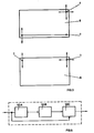
- Fig. 3 zwei Varianten der Anordnung der paßgenauen Öffnungen in der Druckplatte,
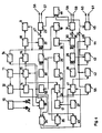
- Fig. 4 ein Blockschaltbild, welches den prinzipiellen Aufbau der Einrichtung in Verbindung mit Zeilenfotosensoren zeigt,
- Fig. 5 ein Blockschaltbild, welches die Generierung der Nullimpulse aus dem Impulsgeber für die winkelversetzten Plattenzylinder der einzelnen Druckwerke einer Mehrfarbendruckmaschine zeigt, in Verbindung mit Zeilenfotosensoren,
- Fig. 6 ein Blockschaltbild, welches den prinzipiellen Aufbau des Spitzenpegelindikators zeigt,
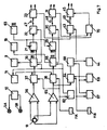
- Fig. 7 ein Blockschaltbild, welches den prinzipiellen Aufbau der Einrichtung in Verbindung mit Positionsdetektoren zeigt,
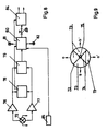
- Fig. 8 ein Blockschaltbild, welches den prinzipiellen Aufbau der Einrichtung mit einem Vier-Quadranten-Positionsdetektor am Beispiel des Umfangsregisters zeigt,
- Fig. 9 den prinzipiellen Aufbau eines Vier-Quadranten-Positionsdetektors.
- Eine Druckplatte 6, die zwei paßgenau zum Druckbild angebrachte Öffnungen 7 gemäß Fig. 3 aufweist, wird auf einem Plattenzylinder 1 grob ausgerichtet und eingespannt. Durch die kreisförmigen Öffnungen (7) sind die Meßorte gekennzeichnet, während durch die Pfeile in Fig. 3 die den Meßorten zugeordneten Stellorte und Stelleinrichtungen gekennzeichnet sind. Gemäß Fig. 1 und 2 ist jeder den Kanal 2 aufweisende Plattenzylinder 1 auf der Antriebsseite und der Bedienungsseite entweder gegenüberliegend oder nur auf einer Seite hintereinander bzw. nebeneinander liegend außerhalb des Druckbereiches und Einfärbebereiches zum Durchleuchten der entsprechend angeordneten paßgenauen Öffnungen 7 mit Beleuchtungseinrichtungen, bestehend aus einer Lichtquelle 5, einer Beleuchtungsoptik 4 und einer Streuscheibe 3 ausgestattet. Die paßgenauen Öffnungen 7 weisen vorzugsweise die Form einer kreisförmigen Paßstanzung auf, die als Lichtmarke erscheint. Es sind aber auch Ovalformen, Rechteck-, Quadrat- oder Dreieckformen geeignet. Diese synchron mit der Rotation des Plattenzylinders 1 erzeugte Lichtmarke wird durch eine feststehend montierte Optik 8 im optimalen Maßstab auf einen maschinenfest montierten digital positionsempfindlichen Zeilenfotosensor 12 im dunklen Umfeld projiziert, wenn die vorzugsweise kreisförmige Paßstanzung (7) hindurchläuft. Am Ende der Achse des Plattenzylinders 1 befinden sich ein Stromübertrager 10 sowie ein Impulsgeber 11 mit zusätzlichem Triggerimpuls. Die Optik 8 dient der Anpassung der Geometrie der paßgenauen Öffnung 7 an die Abmessung geeigneter handelsüblicher, eine Vielzahl von fotoempfindlichen Elementen aufweisender Lichtempfänger. Die von den paßgenauen Öffnungen 7 gebildeten Lichtmarken werden hierzu in einer optimalen feinschrittigen Stufung an den Raster der Lichtempfänger angepaßt. Außerdem kann die nachfolgende Anzeige bereits bei der Messung an eine gängige Skalierung angepaßt werden.
- Ein Zeilenfotosensor weist zeilenförmige fotoempfindliche Bereiche mit z.B. weit über 1.000 fotoempfindlichen Elementen auf, auch als CCD-Zeilen-Bildaufnahme-IC bezeichnet.
- Die Gesamtanordnung ist umkehrbar, d.h. Beleuchtungseinrichtung 3, 4, 5 und Zeilenfotosensor 12 mit vorgeschalteter Optik 8 können ihre gegenüberliegende Position wechseln, so daß jeweils Lichtsender oder Lichtempfänger in einem Durchbruch im Mantel des Plattenzylinders angeordnet mit dem Plattenzylinder 1 rotieren, während jeweils die nicht rotierende Baugruppe maschinenfest angeordnet ist.
- Die Meßstellen der einzelnen Plattenzylinder 1 passieren die ihnen jeweils zugeordnete Sensorik bei einer maschinenbedingten, speziellen Maschinenstellung. Abweichungen nach plus oder minus sind ein Maß für den Passerfehler. Über die Registerfernverstellung können alle Plattenzylinder 1 auf "Null" oder eine für alle Plattenzylinder 1 gleiche Nullabweichung eingestellt werden.
- Gemäß der in Fig. 4 dargestellten Blockschaltung, die die gesamte Einrichtung mit Registerverstellung zeigt, werden den paßgenauen Öffnungen 7, die sich z.B. seitlich unversetzt zueinander an einer Seite der Druckplatte 6 befinden, Lichtquellen 5A und 5B zugeordnet, die über den Stromübertrager 10 mit Strom versorgt werden. Der Impulsgeber 11 liefert bei Rotation des Plattenzylinders 1 gleichmäßig auf den Umfang verteilte Zählimpulse, die über eine Torschaltung 15 an einen Zähler 16 und einen Vorwahlzähler 33 geführt werden. Zusätzlich liefert der Impulsgeber 11 einen Einzelimpuls je Umdrehung, nachfolgend als Nullimpuls bezeichnet. Dieser wird z.B. mechanisch so eingestellt, daß er zu einem Zeitpunkt ausgelöst wird, wenn der nominelle Druckanfang des einzustellenden Plattenzylinders 1 die Position des Zeilenfotosensors 12 passiert. Auch andere Bezugspunkte der Messung sind möglich.
- Die Vorderflanke des Nullimpulses wird in einem Impulsformer 32 (Fig. 5) zu einem Signal von kurzer und von der Maschinengeschwindigkeit unabhängiger Zeitdauer generiert. Es setzt den Zähler 16 und den Vorwahlzähler 33 auf Nullposition sowie einen elektronischen Umschalter 34 auf die Grundposition zurück. Damit ist ein neuer Meßzyklus vorbereitet. Dieser startet, wenn ein Zeitglied 14, angesteuert durch den Nullimpuls, mit einem zeitlich gering versetzten Signal die Torschaltung 15 öffnet und einen Speicher 24 auf "speicherbereit" schaltet. Damit gelangen die Zählimpulse vom Impulsgeber 11 zum Zähler 16 und zum Vorwahlzähler 33, um dort aufaddiert zu werden.
- Die Torschaltung 15 wird durch ein von einem Spitzenpegelindikator 50 ausgelöstes Signal geschlossen. Dieses wird vorbereitet, wenn das Eingangssignal, von einer Oder-Verknüpfung 25 ausgehend, den eingestellten Pegel eines Schwellwertschalters 50A überschritten hat (Fig. 6). Das noch im Anstieg befindliche Signal wird jetzt auch einem Spitzenwertspeicher 50B zugeführt, der den noch ansteigenden Höchstpegel mit geringer Verlustrate speichert und das gespeicherte Signal an einen Eingang eines Kompensators 50C legt. Am zweiten Eingang des Kompensators 50C liegt der von der Oder-Verknüpfung 25 ausgehende Pegel. Diese Pegelhöhe ist erst dann rückläufig, wenn der Zeilenfotosensor 12 durch die rotierende paßgenaue Öffnung 7 geringfügig weniger Licht erhält. Durch die als Folge der dann an den Eingängen des Kompensators 50C anstehenden Spannungsdifferenz wird der von der Baugruppe 50 (Figur 6) ausgehende Impuls ausgelöst und schließt die Torschaltung 15. Der damit erhaltene Zählerstand ist ein Maß für den Weg, den der Umfang des Plattenzylinders 1 bei der vorgegebenen Einstellung von nominellen Druckanfang bis zur paßgenauen Öffnung 7 zurückgelegt hat. Der Spitzenpegelindikator 50 wird vom Zeilenfotosensor 12 angesteuert, wenn die von der Lichtquelle 5 beleuchtete paßgenaue Öffnung 7 vorbei bewegt wird. Die zwischengeschaltete Oder-Verknüpfung 25 verbindet die Einzelsensoren des Zeilenfotosensors 12 zum gemeinsamen Eingang am Spitzenpegelindikator 50. Die Einzelelemente selbst werden über einen Taktgenerator 17 und Clock 27 mit digitalen Signalen angesteuert und weitergeschaltet. Diese Signale werden auch dem Speicher 24 zugeführt, der durch das Ausgangssignal des Zeitgliedes 14 auf Übernahmebereitschaft geschaltet wurde. Den Speicherbefehl liefert eine Und-Verknüpfung 35, wenn der elektronische Umschalter 34 durch den Nullimpuls zuvor zurückgesetzt wurde und den einen Eingang aktiviert, während der zweite Eingang vom Spitzenpegelindikator 50 angesteuert wird. Damit ist im Speicher 24 die Position desjenigen Einzelsensors des Zeilenfotosensors 12 abgespeichert, der auf die rotierende, beleuchtete paßgenaue Öffnung 7 angesprochen hat. Diese Position wird einer Anzeige 19 und einem Vergleicher 30 oder dgl. - bei Bedarf über einen Codeumsetzer 26 - zugeführt, angezeigt bzw. mit einem Sollwert verglichen. Differenzen zwischen Soll- und Istwert dienen, durch einen Automatik-Aus-Schalter 48 unterbrechbar, in einer Ausgangsschaltung 31 zur Bildung der Steuersignale für die axiale Verstellung 58, 59 des Plattenzylinders 1 nach links oder rechts. Der Sollwert für das zu steuernde Druckwerk wird mittels einer Sollwerteinstellung 28 eingegeben und über einen Führungsgrößenwahlschalter 29 dem Vergleicher 30 zugeführt. Der Führungsgrößenwahlschalter 29 erlaubt es, die Führungsgröße auch eines anderen Druckwerkes vorzugeben und damit die Maschine auf gleiches Seitenregister zu fahren. Der Stand des Zählers 16 wird, bei Bedarf über einen Codeumsetzer 18, einer Anzeige 9 und dem Vergleicher 22 aufgeschaltet. Die Übernahme in den Speicher der Anzeige 9, wie auch der Anzeige 19, wird über ein Zeitglied 54 geringfügig verzögert durch den Ausgang des Spitzenpegelindikators 50 ausgelöst. Die Funktionen von Sollwerteinstellung 20, Führungsgrößenwahlschalter 21, Vergleicher 22 und Automatik-Aus-Schalter 47 entsprechen denen der Funktionsgruppen 28, 29, 30 und 48 bei der seitlichen Verstellung. Die Ausgangsschaltung 23 liefert Signale, die den Plattenzylinder 1, relativ zum Antrieb, in Umfangsrichtung 56, 57 vor- und zurückstellen.
- Die Voreinstellung des Vorwahlzählers 33 ist zweckmäßig so zu wählen, daß die Koinzidenz zwischen dieser und dem Zählerstand dann eintritt, wenn die zweite paßgenaue Öffnung 7, die sich seitlich unversetzt zur ersten im hinteren Druckplattenbereich befindet und von der Lichtquelle 5B beleuchtet wird, kurz vor dem Zeilenfotosensor 12 befindet. Der Ausgang des Vorwahlzählers 33 setzt den elektronischen Umschalter 34, der als Folge sein Ausgangssignal von der Und-Verknüpfung 35 auf eine Und-Verknüpfung 40 umlegt und einen Speicher 41 aktiviert, der dieselbe Positionsinformation des Zeilenfotosensors 12 erhält wie der Speicher 24. Durch einen Ausgangsimpuls des Spitzenpegelindikators 50 wird jetzt bei der Und-Verknüpfung 40 ein Signal ausgelöst, daß die am Speicher 41 anstehende Positionsinformation übernimmt und speichert und, bei Bedarf über einen Codeumsetzer 42, an eine Anzeige 44 und einen Vergleicher 43 führt. Dieser erhält die gleiche Führungsgröße wie der Vergleicher 30. Eine mit dem Automatik-Aus-Schalter 49 abtrennbare Ausgangsschaltung 45 steuert den Antrieb der Zylinderschrägstellung 60, 61 vor und zurück. Die automatische Zylinderschrägstellung ist über eine Oder-Verknüpfung 46 erst aktiviert, wenn von keiner der Ausgangsschaltungen 23 und 31 noch Steuersignale ausgehen. Die Übernahme in den Speicher der Anzeige 44 wird über ein Zeitglied 55 geringfügig verzögert, vom Speichersignal der Und-Verknüpfung 40 ausgelöst.
- Das Blockschaltbild für die weiteren Druckwerke einer Druckmaschine ist identisch mit dem obigen, aber der Einschränkung, daß auf weitere Impulsgeber 11 verzichtet werden kann, wenn gemäß Fig. 5 für jedes zusätzliche Druckwerk ein Vorwählzahler 51 bis 53 bei einer Vierfarbenmaschine zur Anwendung kommt. Die Anzahl der Vorwahlschritte ist so zu wählen, daß die Signalauslösung des Vorwahlzählers erfolgt, wenn der nominelle Druckanfang des jeweils zu steuernden Plattenzylinders 1 die Position des jeweiligen Zeilenfotosensors 12 passiert. Mit Signalen der Vorwahlzähler 51, 52, 53 werden die Impulsformer 32 der jeweiligen Druckwerkssteuerungen aktiviert. In der Zeichnung (Fig. 4) sind die einzelnen Druckwerke bei den Bauteilen z.B. 21, 22, 29 und 30 durch Pfeile angedeutet.
- Die gemäß dem vorstehend beschriebenen Ausführungsbeispiel vorgesehene zweite seitliche Messung zur Zylinderschrägstellung entfällt, wenn beidseitig des Zylinders angeordnete paßgenaue Öffnungen 7 abgetastet werden sollten. Zur Messung werden dann noch auf der gegenüberliegenden Seite der Druckplatte 6 die Baugruppen 9, 12, 15, 16, 22, 23, 25 und 50 benötigt. Das bedeutet, daß zur Zylinderschrägstellungsmessung in diesem Fall der Impulsformer 32, das Zeitglied 14, der Taktgenerator 17 mit Clock 27, die Sollwerteinstellung 20 und der Führungsgrößenwahlschalter 21 gemeinsam benutzt werden können.
- Im Folgenden wird die Erfindung in einer weiteren Ausführungsform mit Positionsdetektoren 13 anstelle der Zeilenfotosensoren 12 erläutert. Ein Positionsdetektor arbeitet wie ein Potentiometer, dem ein Strom über den Abgriffkontakt zugeführt wird. Der teilt sich in zwei Ströme zu den Endkontakten auf. Die Differenz der Ströme entspricht der Position des Abgriffkontaktes, kontinuierlich und mit hoher Auflösung. Positionsdetektoren werden in verschiedenen Größen und Gehäusen handelsüblich als einachsige und zweiachsige Positionsdetektoren angeboten. Gemäß Fig. 7 befinden sich am Ende der Achse des Plattenzylinders 1 der Stromübertrager 10 und ein Impulsgeber 11 zur Erzeugung von zwei voneinander unabhängigen, auf beliebigen Zylinderwinkel im Formatbereich justierbaren Triggerimpulsen 11A und 11B. Vom Positionsdetektor 13 gelangen die zur Umfangspassermessung relevanten Signale über einen Verstärker 36, der als Option zum Positionsdetektor aus dessen Ausgangssignalen als Auswerteeinheit ein positionproportionales Ausgangssignal liefert, zum A/D-Wandler mit Sample and Hold 37. Der Impulsgeber 11A ist so eingestellt, daß bei Nullstellung des Plattenzylinders 1 zum Zylinderantrieb und Mittigstellung zum Druckzylinder ein Triggersignal ausgelöst wird, wenn das Zentrum der mit dem Plattenzylinder 1 rotierenden Lichtquelle 5A radial dem stehenden Positionsdetektor 13 gegenüber steht. Die paßgenaue Öffnung 7 ist in der Druckform 6 im Bereich des Druckanfanges so angebracht, daß sie sich bei optimaler Plattenmontage ebenfalls im Zentrum der Beleuchtungseinrichtung 3, 4, 5 befindet. Der im Sample-Zustand befindliche A/D-Wandler 37 wird mit dem Impulsgeber 11A zeitgleich mit einem A/D-Wandler 38 auf "Hold" geschaltet und gibt sein digitalisiertes Signal an einen Speicher 39, der über das Zeitglied 62 geringfügig verzögert das Übernahmesignal erhält. Die im Speicher 39 abgelegte Position der paßgenauen Öffnung 7 wird umfangsbezogen mit der Anzeige 9 angezeigt. Die entsprechende Registerverstellung kann nach Anzeige manuell durch Verstellen des Zylinders zum Antrieb in bekannter Weise vollzogen werden. Der Inhalt des Speichers 39 wird auch an einen Führungsgrößenwahlschalter 21, die nicht dargestellten Führungsgrößenwahlschalter der weiteren Druckwerke der Druckmaschine und an den Vergleicher 22 geführt. Mittels des Führungsgrößenwahlschalters 21 kann entweder der Istwert eines jeden Druckwerkes oder ein für alle Druckwerke gleicher, vom Referenzsignalgeber 63 erzeugter Signalpegel vorgegeben werden, der zweckmäßig der Druckplattengrundeinstellung entspricht. Im Vergleicher 22 entsteht aus dem Soll-Istwert-Vergleich ein durch den Automatik-Aus-Schalter 47 unterbrechbares Signal, das in der Ausgangsschaltung 23 entsprechend der vom Sollwert abweichenden, gemessenen Plattenumfangsposition korrigierende Steuerimpulse an die Umfangsverstellung des Plattenzylinders 1 gibt.
- Mit dem gleichen, zweidimensionalen Positionssensor 13 und dem Verstärker 65, dem A/D-Wandler mit Sample and Hold 38, dem Speicher 66, der Anzeige 19, dem Führungsgrößenwahlschalter 29, dem Vergleicher 30, dem Automatik-Aus-Schalter 48 und der Ausgangsschaltung 31 erfolgt in gleicher Weise wie oben beschrieben die Messung und Anzeige der seitlichen Plattenpositionen und bei Bedarf auch die seitliche Zylinderverstellung. Nach der zeitgleichen Übernahme der Positionswerte von den A/D-Wandlern 37 und 38 in die Speicher 39, 66 werden geringfügig über das Zeitglied 71 verzögert die A/D-Wandler 37 und 38 in die Sample-Funktion zurückgesetzt und damit für eine neue Wandlung vorbereitet.
- Zur Schrägbogenmessung befindet sich die zweite Paßstanzung in Umfangsrichtung seitlich unversetzt am Plattenformatende außerhalb des Einfärbebereiches (s. Fig. 3). Dort befindet sich im Plattenzylinder 1 auch die zweite Beleuchtungseinrichtung 3, 4, 5 mit der Lichtquelle 5B. Der Impulsgeber 11B wird so eingestellt, daß das Signal zu dem Zeitpunkt ausgelöst wird, bei dem die Mitte der Lichtquelle 5B bei Nullstellung des Plattenzylinders 1 zum Antrieb und seiner Mittigstellung zum Druckzylinder radial dem stehenden Positionsdetektor 13 gegenüber steht. Damit wird ein A/D-Wandler mit Sample and Hold 64 mit dem vom Verstärker 65 kommenden augenblicklich anstehenden Analogsignal auf "Hold" geschaltet und die A/D-Wandlung vorgenommen. Über ein Zeitglied 67 geringfügig verzögert wird das digitalisierte Signal im Speicher 68 gespeichert und mittels der Anzeige 44 angezeigt. Anschließend wird, durch das Zeitglied 69 geringfügig verzögert, der A/D-Wandler 64 auf Sample-Funktion zurückgesetzt und damit für den folgenden Meßzyklus vorbereitet. Der Vergleicher 43 erhält seinen Istwert vom Speicher 68, seinen Sollwert, wie auch der Vergleicher 30, vom Führungsgrößenwahlschalter 29. Er steuert, durch den Automatik-Aus-Schalter 49 abschaltbar, die Ausgangsschaltung 45, die ihrerseits die Zylinderschrägverstellung zur Passerkorrektur den Messwerten entsprechend einschaltet. Dies ist durch eine Oder-Verknüpfung 70 gesperrt, wenn von einer oder beiden Ausgangsschaltungen 23 und/oder 31 noch ein Stellsignal ausgeht.
- Bei veränderter Anordnung der Positionsdetektoren 13, der paßgenauen Öffnungen 7 und der entsprechenden Beleuchtungseinrichtungen 3, 4, 5 kann auch beidseitig des Plattenzylinders 1 gemessen werden. Dann sind neben den beiden Lichtquellen 5A, 5B zu einem zweidimensionalen Positionsdetektor 13 noch ein weiterer, eindimensionaler Positionsdetektor 13 notwendig. Ein Beispiel mit geeigneten Orten der Paßstanzung ist in Fig. 3 wiederum gezeigt. Das oben beschriebene Blockschaltbild muß in einigen Punkten abgeändert werden. Es entfällt der Impulsgeber 11B. Für den eindimensionalen Positionsdetektor 13 ist ein zusätzlicher nicht dargestellter Verstärker notwendig, dessen Signale über eine entsprechende Baugruppenkette 43, 44, 45, 49, 64, 68 weiter behandelt werden. Alle A/D-Wandler und Speicher werden vom Impulsgeber 11A und den nachgeschalteten Zeitgliedern parallel gesteuert. Der Vergleicher 43 erhält seine Führungsgröße wie üblich vom Führungsgrößenwahlschalter 21. Mit dem Implusgeber 11B entfallen die Zeitglieder 67 und 69.
- Ein Positionsdetektor anderer Bauart ist der in Fig. 9 gezeigte Vier-Quadranten-Positionsdetektor 72. Seine meist rund gestaltete, lichtempfindliche Oberfläche besteht aus vier sektorförmigen Einzelsensoren 73 geringen gegenseitigen Zwischenraumes, deren Spitzen in der Mitte zentral zusammentreffen und die durch elektrisch isolierende Trennlinien 74 kreuzartig getrennt sind. Mit ihm ist feststellbar, auf welchem der vier Sektoren ohne genaue Ortsbestimmung die vornehmlich punktförmige Lichtmarke 75 auftrifft. Dies ist ausschließlich im Zentrum möglich, weil durch eine an dieser Stelle auftreffende Lichtmarke 75 alle vier Einzelsensoren 73 gleich beleuchtet werden können und damit die Summe aller Ausgangssignale zu Null wird. Eine Auswerteschaltung am Beispiel eines Umfangsmeßkanals ist in Fig. 8 dargestellt.
- Die Signale der beiden diametral gegenüberstehenden Sektoren des Vier-Quadranten-Positionsdetektors 72 werden nach Verstärkung durch die Verstärker 76 und 77 an die Komparatoren 78 und 79 geführt. Der Komparator 79 ist mit einem engen Toleranzfeld versehen. Sein Ausgang an den Speicher 80 bestimmt, ob und in welcher Richtung ein Passerfehler vorliegt. Entsprechend werden die optischen oder akustischen Anzeigen 81 und 82 angesteuert bzw. es werden die Steuersignale der mit Automatik-Aus-Schalter 83 abtrennbaren Ausgangsschaltung 84 zur Plattenzylinderverstellung aktiviert. Sie bestehen aus Impulsen, die intensiver werden, wenn der Komparator 78 durch eine größere Eingangsspannungsdifferenz angesteuert wurde. Im Speicher 80 werden die Ausgangssignale des Komparators 78 zur Impulsintensitätssteuerung der Ausgangsschaltung 84 und des Komperators 79 zur Auslösung der Richtungsimpulse an der gleichen Ausgangsschaltung übernommen, wenn ein Impulsgeber 85 mit Triggerimpuls ausgelöst wird. Die Einstellung der Trigger erfolgt nach dem bereits zuvor beschriebenen Verfahren. Auch zur Seiten- und Schrägbogenpassung ist die aufgezeigte Schaltung anzuwenden.
- Bei einer beidseitigen Messung kann einer der Positionsdetektoren 72 durch ein eindimensionales System, einem Duo-Sensor ersetzt werden. Bei ihm erfolgt die Messung an der geradlinigen, isolierten Trennlinie zwischen den beiden, meist rechtwinkeligen Sensorelementen.
- Angenommen der außermittig auf den Vier-Quadranten-Positionsdetektor 72 auftreffende Lichtstrahl fällt mit gleichem Flächenanteil auf den oberen und unteren Sektor und erzeugt damit an den Ausgängen a und a′ ein identisches Signal mit der Differenz 0. Dann wird keiner der Komparatoren 78, 79 angesteuert. Anders liegen die Verhältnisse zwischen den Ausgängen b und b′, dort seien unterschiedliche Sensorflächen beleuchtet. Als Folge dieses Differenzsignales spricht dann mindestens ein Komparator 78, 79 an, der die Richtung des Passerfehlers zur Anzeige bringt und bei entsprechender Stellung des Schalters 83 auch die Passerkorrektur einleitet.
- Die Bewegung des Stellantriebes wird, ohne daß eine genaue Lagebestimmung zuvor erforderlich war, dann abgestoppt, wenn das Verhältnis der beleuchteten Sensorflächen, das durch Messen der Ausgänge a, a′ bzw. b, b′ erfaßt ist, gleich 1 bzw. die Differenz gleich 0 ist.
- Die Ausgangssignale der Ausgangsschaltung können in bekannter Weise je nach dem Konzept der Maschinensteuerung je einen elektromechanischen Schalter (Relais oder Schütz) oder auch einer elektronischer Schalteinrichtung (z.B. Halbleiterrelais, Thyristoren, usw.) zum Schalten eines Motors für Rechts- oder Linkslauf aufweisen, aber auch zum Einschalten von Magnetventilen bei hydraulischer oder pneumatischer Passerverstellung herangezogen werden.
-
- 1 Plattenzylinder
- 2 Kanal
- 3 Streuscheibe
- 4 Beleuchtungsoptik
- 5 Lichtquelle
- 6 Druckform
- 7 paßgenaue Öffnung
- 8 Optik
- 9 Anzeige
- 10 Stromübertrager
- 11 Impulsgeber
- 12 Zeilenfotosensor
- 13 Positionsdetektor
- 14 Zeitglied
- 15 Torschaltung
- 16 Zähler
- 17 Taktgenerator
- 18 Codeumsetzer
- 19 Anzeige
- 20 Sollwerteinstellung
- 21 Führungsgrößenwahlschalter
- 22 Vergleicher
- 23 Ausgangsschaltung
- 24 Speicher
- 25 Oder-Verknüpfung
- 26 Codeumsetzer
- 27 Clock
- 28 Sollwerteinstellung
- 29 Führungsgrößenwahlschalter
- 30 Vergleicher
- 31 Ausgangsschaltung
- 32 Impulsformer
- 33 Vorwahlzähler
- 34 Umschalter
- 35 Und-Verknüpfung
- 36 Verstärker
- 37 A/D-Wandler
- 38 A/D-Wandler
- 39 Speicher
- 40 Und-Verknüpfung
- 41 Speicher
- 42 Codeumsetzer
- 43 Vergleicher
- 44 Anzeige
- 45 Ausgangsschaltung
- 46 Oder-Verknüpfung
- 47 Automatik-Aus-Schalter
- 48 Automatik-Aus-Schalter
- 49 Automatik-Aus-Schalter
- 50 Spitzenpegelindikator
- 51 Vorwahlzähler
- 52 Vorwahlzähler
- 53 Vorwahlzähler
- 54 Zeitglied
- 55 Zeitglied
- 56 Zylinderumfangsverstellung vor
- 57 Zylinderumfangsverstellung zurück
- 58 Zylinderaxialverstellung links
- 59 Zylinderaxialverstellung rechts
- 60 Zylinderschrägstellung vor
- 61 Zylinderschrägstellung zurück
- 62 Zeitglied
- 63 Referenzsignalgeber
- 64 A/D-Wandler
- 65 Verstärker
- 66 Speicher
- 67 Zeitglied
- 68 Speicher
- 69 Zeitglied
- 70 Oder-Verknüpfung
- 71 Zeitglied
- 72 Vier-Quadranten-Positionsdetektor
- 73 Einzelsensoren
- 74 Trennlinien
- 75 Lichtmarke
- 76 Verstärker
- 77 Verstärker
- 78 Komparator
- 79 Komparator
- 80 Speicher
- 81 Anzeige
- 82 Anzeige
- 83 Automatik-Aus-Schalter
- 84 Ausgangsschaltung
- 85 Impulsgeber
Claims (6)
Priority Applications (1)
| Application Number | Priority Date | Filing Date | Title |
|---|---|---|---|
| AT87107861T ATE67122T1 (de) | 1986-06-14 | 1987-05-30 | Einrichtung an druckmaschinen mit stelleinrichtungen fuer umfangs-, seiten- und diagonalregister. |
Applications Claiming Priority (6)
| Application Number | Priority Date | Filing Date | Title |
|---|---|---|---|
| DE3620139 | 1986-06-14 | ||
| DE3620139 | 1986-06-14 | ||
| DE3620138 | 1986-06-14 | ||
| DE3620138 | 1986-06-14 | ||
| DE3703998 | 1987-02-10 | ||
| DE19873703998 DE3703998A1 (de) | 1986-06-14 | 1987-02-10 | Einrichtung an druckmaschinen mit stelleinrichtungen fuer umfangs-, seiten- und diagonalregister |
Publications (3)
| Publication Number | Publication Date |
|---|---|
| EP0249788A2 EP0249788A2 (de) | 1987-12-23 |
| EP0249788A3 EP0249788A3 (en) | 1989-10-25 |
| EP0249788B1 true EP0249788B1 (de) | 1991-09-11 |
Family
ID=27194495
Family Applications (1)
| Application Number | Title | Priority Date | Filing Date |
|---|---|---|---|
| EP87107861A Expired - Lifetime EP0249788B1 (de) | 1986-06-14 | 1987-05-30 | Einrichtung an Druckmaschinen mit Stelleinrichtungen für Umfangs-, Seiten- und Diagonalregister |
Country Status (4)
| Country | Link |
|---|---|
| EP (1) | EP0249788B1 (de) |
| JP (1) | JPH0667618B2 (de) |
| AT (1) | ATE67122T1 (de) |
| DE (1) | DE3772857D1 (de) |
Families Citing this family (3)
| Publication number | Priority date | Publication date | Assignee | Title |
|---|---|---|---|---|
| DE3930782C1 (de) * | 1989-09-14 | 1991-01-24 | Heidelberger Druckmaschinen Ag, 6900 Heidelberg, De | |
| DE4014706C2 (de) * | 1990-05-08 | 1994-06-01 | Heidelberger Druckmasch Ag | Verfahren zum Ermitteln von Registerfehlern auf einem mit Registermarken versehenen Druckerzeugnis |
| CN102454954B (zh) * | 2010-10-29 | 2013-07-17 | 鸿骐新技股份有限公司 | 适用于基板的高速视觉定位装置及其方法 |
Family Cites Families (8)
| Publication number | Priority date | Publication date | Assignee | Title |
|---|---|---|---|---|
| GB544830A (en) * | 1940-02-27 | 1942-04-29 | Champlain Corp | Improvements in or relating to register control apparatus for maintaining the operation of a rotating element on a travelling web in register with any prior conditioningof said web |
| US2448292A (en) * | 1943-10-22 | 1948-08-31 | Cottrell C B & Sons Co | Geared adjustment means |
| FR1036401A (fr) * | 1950-05-02 | 1953-09-08 | Licentia Gmbh | Dispositif pour la détermination de la position relative des images ou des repèresd'impression sur des bandes de papier ou d'étoffe |
| JPS5814752A (ja) * | 1981-07-21 | 1983-01-27 | Komori Printing Mach Co Ltd | 多色印刷機の見当自動調整装置 |
| DE3136703C1 (de) * | 1981-09-16 | 1982-11-04 | M.A.N.- Roland Druckmaschinen AG, 6050 Offenbach | Einrichtungen an Druckmaschinen mit Registerverstelleinrichtungen |
| DE3302200A1 (de) * | 1982-01-25 | 1983-08-04 | Dai Nippon Insatsu K.K., Tokyo | Verfahren zum einrichten einer offset-druckpresse und vorrichtungen zur durchfuehrung des verfahrens |
| DD227095A1 (de) * | 1984-10-05 | 1985-09-11 | Polygraph Leipzig | Einrichtung zur registerkontrolle und -verstellung |
| US4680806A (en) * | 1984-12-04 | 1987-07-14 | Koenig & Bauer Aktiengesellschaft | Edge location measuring head |
-
1987
- 1987-05-30 EP EP87107861A patent/EP0249788B1/de not_active Expired - Lifetime
- 1987-05-30 AT AT87107861T patent/ATE67122T1/de not_active IP Right Cessation
- 1987-05-30 DE DE8787107861T patent/DE3772857D1/de not_active Expired - Lifetime
- 1987-06-15 JP JP62147189A patent/JPH0667618B2/ja not_active Expired - Lifetime
Also Published As
| Publication number | Publication date |
|---|---|
| JPH0667618B2 (ja) | 1994-08-31 |
| EP0249788A2 (de) | 1987-12-23 |
| DE3772857D1 (de) | 1991-10-17 |
| JPS62299340A (ja) | 1987-12-26 |
| EP0249788A3 (en) | 1989-10-25 |
| ATE67122T1 (de) | 1991-09-15 |
Similar Documents
| Publication | Publication Date | Title |
|---|---|---|
| DE3703998A1 (de) | Einrichtung an druckmaschinen mit stelleinrichtungen fuer umfangs-, seiten- und diagonalregister | |
| EP0126211B1 (de) | Inkrementale Längen- oder Winkelmesseinrichtung | |
| EP0241773B1 (de) | Bestimmung des Registerfehlers beim Mehrfarbendruck | |
| DE69126979T2 (de) | Abstandsbedienungssystem hauptsächlich für filmkameras und verfahren dafür | |
| DE3037810C2 (de) | Inkrementale Längen- oder Winkelmeßeinrichtung | |
| DE3836310C2 (de) | Verfahren zum Einstellen einer Wendeeinrichtung an einer Druckmaschine mit mehreren Druckwerken | |
| DE19628765A1 (de) | Verfahren und Vorrichtung zur Positionierung von nicht-geradlinigen, insbesondere rotierenden Maschinenteilen | |
| DE2322194C2 (de) | Einrichtung zum Anlegen eines Bogens | |
| DE1803925C3 (de) | Steuereinrichtung eines Vervielfältigungsgerätes | |
| EP0249788B1 (de) | Einrichtung an Druckmaschinen mit Stelleinrichtungen für Umfangs-, Seiten- und Diagonalregister | |
| EP1843898B2 (de) | Registerverfahren | |
| DE3506782C2 (de) | Vorjustiergerät für Wafer | |
| DE1477390A1 (de) | Geraet zur Anzeige der Verschiebungsgroesse eines Schlittens | |
| DE2901980A1 (de) | Einrichtung zur steuerung einer druckmaschine | |
| DE2044663C3 (de) | Vorrichtung zum Ablesen von Marken auf der Druckform einer Offsetdruckmaschine | |
| DE2124356C3 (de) | Vorrichtung zum Einstellen der Magnetkraft eines Permanentmagneten einer elektrischen Einrichtung | |
| EP0349813B1 (de) | Blendeneinstellvorrichtung in einem fotografischen Vergrösserungs- oder Kopiergerät mit mehreren Objektiven mit verstellbarer Blende | |
| DE2346023A1 (de) | Radwinkelmessgeraet | |
| DE3611204C2 (de) | ||
| EP0388904B1 (de) | Opto-elektronisches Justierverfahren und Einrichtung zur automatischen rechnergesteuerten Positionierung der Druckschablonen einer Rotationssiebdruckmaschine | |
| DE2902868A1 (de) | Vorrichtung zur bestimmung des druckenden flaechenanteiles von druckformen | |
| DE2557944B2 (de) | Anordnung zur Erzeugung von Austastsignalen für die Registerregelung | |
| DE2505380A1 (de) | Digitale vorrichtung zur stillsetzung des stempels von exzenterpressen, schneid- und nibbelmaschinen im bereich des oberen totpunktes | |
| DE3420187C1 (de) | Positionsmeßeinrichtung | |
| AT207130B (de) | Abschaltvorrichtung für Waagen, insbesondere Neigungswaagen |
Legal Events
| Date | Code | Title | Description |
|---|---|---|---|
| PUAI | Public reference made under article 153(3) epc to a published international application that has entered the european phase |
Free format text: ORIGINAL CODE: 0009012 |
|
| AK | Designated contracting states |
Kind code of ref document: A2 Designated state(s): AT CH DE FR GB IT LI NL SE |
|
| PUAL | Search report despatched |
Free format text: ORIGINAL CODE: 0009013 |
|
| AK | Designated contracting states |
Kind code of ref document: A3 Designated state(s): AT CH DE FR GB IT LI NL SE |
|
| 17P | Request for examination filed |
Effective date: 19890922 |
|
| 17Q | First examination report despatched |
Effective date: 19910211 |
|
| ITF | It: translation for a ep patent filed | ||
| GRAA | (expected) grant |
Free format text: ORIGINAL CODE: 0009210 |
|
| AK | Designated contracting states |
Kind code of ref document: B1 Designated state(s): AT CH DE FR GB IT LI NL SE |
|
| REF | Corresponds to: |
Ref document number: 67122 Country of ref document: AT Date of ref document: 19910915 Kind code of ref document: T |
|
| REF | Corresponds to: |
Ref document number: 3772857 Country of ref document: DE Date of ref document: 19911017 |
|
| ET | Fr: translation filed | ||
| GBT | Gb: translation of ep patent filed (gb section 77(6)(a)/1977) | ||
| PLBE | No opposition filed within time limit |
Free format text: ORIGINAL CODE: 0009261 |
|
| STAA | Information on the status of an ep patent application or granted ep patent |
Free format text: STATUS: NO OPPOSITION FILED WITHIN TIME LIMIT |
|
| 26N | No opposition filed | ||
| EAL | Se: european patent in force in sweden |
Ref document number: 87107861.4 |
|
| PGFP | Annual fee paid to national office [announced via postgrant information from national office to epo] |
Ref country code: CH Payment date: 19950418 Year of fee payment: 9 |
|
| PGFP | Annual fee paid to national office [announced via postgrant information from national office to epo] |
Ref country code: GB Payment date: 19950419 Year of fee payment: 9 |
|
| PGFP | Annual fee paid to national office [announced via postgrant information from national office to epo] |
Ref country code: FR Payment date: 19950420 Year of fee payment: 9 |
|
| PGFP | Annual fee paid to national office [announced via postgrant information from national office to epo] |
Ref country code: SE Payment date: 19950424 Year of fee payment: 9 |
|
| PGFP | Annual fee paid to national office [announced via postgrant information from national office to epo] |
Ref country code: AT Payment date: 19950426 Year of fee payment: 9 |
|
| PGFP | Annual fee paid to national office [announced via postgrant information from national office to epo] |
Ref country code: NL Payment date: 19950531 Year of fee payment: 9 |
|
| PG25 | Lapsed in a contracting state [announced via postgrant information from national office to epo] |
Ref country code: GB Effective date: 19960530 Ref country code: AT Effective date: 19960530 |
|
| PG25 | Lapsed in a contracting state [announced via postgrant information from national office to epo] |
Ref country code: SE Effective date: 19960531 Ref country code: LI Effective date: 19960531 Ref country code: CH Effective date: 19960531 |
|
| PG25 | Lapsed in a contracting state [announced via postgrant information from national office to epo] |
Ref country code: NL Effective date: 19961201 |
|
| REG | Reference to a national code |
Ref country code: CH Ref legal event code: PL |
|
| GBPC | Gb: european patent ceased through non-payment of renewal fee |
Effective date: 19960530 |
|
| PG25 | Lapsed in a contracting state [announced via postgrant information from national office to epo] |
Ref country code: FR Effective date: 19970131 |
|
| EUG | Se: european patent has lapsed |
Ref document number: 87107861.4 |
|
| NLV4 | Nl: lapsed or anulled due to non-payment of the annual fee |
Effective date: 19961201 |
|
| REG | Reference to a national code |
Ref country code: FR Ref legal event code: ST |
|
| PGFP | Annual fee paid to national office [announced via postgrant information from national office to epo] |
Ref country code: DE Payment date: 19980420 Year of fee payment: 12 |
|
| PG25 | Lapsed in a contracting state [announced via postgrant information from national office to epo] |
Ref country code: DE Free format text: LAPSE BECAUSE OF NON-PAYMENT OF DUE FEES Effective date: 20000301 |
|
| PG25 | Lapsed in a contracting state [announced via postgrant information from national office to epo] |
Ref country code: IT Free format text: LAPSE BECAUSE OF NON-PAYMENT OF DUE FEES;WARNING: LAPSES OF ITALIAN PATENTS WITH EFFECTIVE DATE BEFORE 2007 MAY HAVE OCCURRED AT ANY TIME BEFORE 2007. THE CORRECT EFFECTIVE DATE MAY BE DIFFERENT FROM THE ONE RECORDED. Effective date: 20050530 |