EP0249451A2 - Thermostat à boule de cire - Google Patents
Thermostat à boule de cire Download PDFInfo
- Publication number
- EP0249451A2 EP0249451A2 EP87305116A EP87305116A EP0249451A2 EP 0249451 A2 EP0249451 A2 EP 0249451A2 EP 87305116 A EP87305116 A EP 87305116A EP 87305116 A EP87305116 A EP 87305116A EP 0249451 A2 EP0249451 A2 EP 0249451A2
- Authority
- EP
- European Patent Office
- Prior art keywords
- guide member
- piston
- diaphragm
- thermostat
- secured
- Prior art date
- Legal status (The legal status is an assumption and is not a legal conclusion. Google has not performed a legal analysis and makes no representation as to the accuracy of the status listed.)
- Granted
Links
Images


Classifications
-
- F—MECHANICAL ENGINEERING; LIGHTING; HEATING; WEAPONS; BLASTING
- F16—ENGINEERING ELEMENTS AND UNITS; GENERAL MEASURES FOR PRODUCING AND MAINTAINING EFFECTIVE FUNCTIONING OF MACHINES OR INSTALLATIONS; THERMAL INSULATION IN GENERAL
- F16K—VALVES; TAPS; COCKS; ACTUATING-FLOATS; DEVICES FOR VENTING OR AERATING
- F16K17/00—Safety valves; Equalising valves, e.g. pressure relief valves
- F16K17/36—Safety valves; Equalising valves, e.g. pressure relief valves actuated in consequence of extraneous circumstances, e.g. shock, change of position
- F16K17/38—Safety valves; Equalising valves, e.g. pressure relief valves actuated in consequence of extraneous circumstances, e.g. shock, change of position of excessive temperature
-
- G—PHYSICS
- G05—CONTROLLING; REGULATING
- G05D—SYSTEMS FOR CONTROLLING OR REGULATING NON-ELECTRIC VARIABLES
- G05D23/00—Control of temperature
- G05D23/01—Control of temperature without auxiliary power
- G05D23/13—Control of temperature without auxiliary power by varying the mixing ratio of two fluids having different temperatures
- G05D23/1306—Control of temperature without auxiliary power by varying the mixing ratio of two fluids having different temperatures for liquids
- G05D23/132—Control of temperature without auxiliary power by varying the mixing ratio of two fluids having different temperatures for liquids with temperature sensing element
- G05D23/1333—Control of temperature without auxiliary power by varying the mixing ratio of two fluids having different temperatures for liquids with temperature sensing element measuring the temperature of incoming fluid
-
- G—PHYSICS
- G05—CONTROLLING; REGULATING
- G05D—SYSTEMS FOR CONTROLLING OR REGULATING NON-ELECTRIC VARIABLES
- G05D23/00—Control of temperature
- G05D23/01—Control of temperature without auxiliary power
- G05D23/02—Control of temperature without auxiliary power with sensing element expanding and contracting in response to changes of temperature
- G05D23/021—Control of temperature without auxiliary power with sensing element expanding and contracting in response to changes of temperature the sensing element being a non-metallic solid, e.g. elastomer, paste
-
- Y—GENERAL TAGGING OF NEW TECHNOLOGICAL DEVELOPMENTS; GENERAL TAGGING OF CROSS-SECTIONAL TECHNOLOGIES SPANNING OVER SEVERAL SECTIONS OF THE IPC; TECHNICAL SUBJECTS COVERED BY FORMER USPC CROSS-REFERENCE ART COLLECTIONS [XRACs] AND DIGESTS
- Y10—TECHNICAL SUBJECTS COVERED BY FORMER USPC
- Y10S—TECHNICAL SUBJECTS COVERED BY FORMER USPC CROSS-REFERENCE ART COLLECTIONS [XRACs] AND DIGESTS
- Y10S277/00—Seal for a joint or juncture
- Y10S277/91—O-ring seal
Definitions
- the present invention relates to a wax-pellet thermostat for automotive engines.
- the wax-pellet thermostat comprises a thermo-sensitive device and a valve device.
- the thermo-sensitive device includes a steel piston, a guide member slidably engaged with the piston, a rubber diaphragm around the piston, and a wax.
- the piston is sealed by a sealing device provided in the guide member.
- the sealing device deteriorates, a space in the diaphragm is communicated with a coolant passage. Under such a condition, when the temperature of coolant rapidly decreases from high temperature (about 100°C) to low temperature(below 40°C), the space in the diaphragm becomes vacuum. Accordingly, the coolant is inducted into the space.
- the coolant in the space cannot be discharged.
- the valve is slightly raised by the coolant in the space, which causes the opening temperature of the valve to decrease.
- the engine is overcooled, thereby reducing the thermal efficiency of the engine and increasing the amount of emissions.
- the amount of the coolant in the space increases with time, so that the valve lift increases, which causes troubles of the engine.
- An object of the invention is to provide a thermostat which may automatically discharge the coolant inducted in a space.
- Another object of the invention is to provide a thermostat which may prevent the induction of coolant.
- a thermostat having a housing having a valve seat, a piston secured to the housing, a guide member slidably mounted on the piston, a valve secured to the guide member, a diaphragm secured to the guide member around a lower portion of the piston, a heat conductive cylinder secrued to the guide member and surrounding the diaphragm, and a wax provided in the cylinder.
- the thermostat has a gap provided at a portion between the guide member and the diaphragm around the piston so as to accumulate coolant entered along the piston and to discharge from the guide member when the wax expands to cause a part of the diaphragm to enter into the gap.
- the gap is formed in the guide member around the piston adjacent the top surface of the diaphragm.
- the gap is formed in the diaphragm at the top thereof, and a seal is provided in the guide member at a top portion thereof around the piston so as to prevent the enter of coolant.
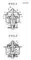
- the thermostat of the present invention comprises a housing 2 forming a valve seat 1, a frame 3 secured to the housing 2.
- a thermo-sensitive device 5 comprises a steel piston 8 secured to the housing 2 at a top 12, guide member 6 slidably engaged with the piston 8, primary valve 4 secured to the guide member 6, heat conductive cylinder 11 secured to the guide member 6, rubber diaphragm 9 secured to the guide member 6, wax pellet 10 provided in the cylinder 11, and seal packing 15 for preventing counter flow of coolant.
- a return coil spring 7 disposed surrounding the cylinder 11 is provided between the primary valve 4 and the bottom of the frame 3.
- a gap 14 is formed in the guide member 6 at a portion around the piston 8 and adjacent the top surface of rubber diaphragm 9.
- Fig. 2 shows a valve closed state.
- the wax 10 expands. This forces the rubber diaphragm 9 against the steel piston 8.
- the wax 10 overcomes the coil spring 7 and the thermo-sensitive device 5 moves downward, thereby opening the valve 4.
- the thermostat cools, the wax 10 contracts.
- the coil spring 7 returns the valve to the closed position as shown in Fig. 2. Since a space 13 is formed in the diaphragm 9 at the bottom thereof, the valve 4 is securely pressed against the seat 1.
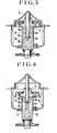
- Figs. 3 and 4 show a conventional thermostat.
- a coolant is inducted in space 13 in the diaphragm 9.
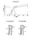
- Fig. 5 shows a valve lift curve A of the thermostat of the present invention shown in Figs. 1 and 2 and a valve lift curve B of the thermostat shown in Figs. 3 and 4.
- the valve 4 of the thermostat of Fig. 2 begins to open at 88°C and fully opens at 100°C (point D) where the valve lift is 8.5 mm. Thereafter the valve is lifted by a small increment (0.07 mm per 1°C) until 130°C by thermal expansion of the wax 10.
- valve 4 of the thermostat of Fig. 3 in which the coolant is inducted in the diaphragm 9 is fully opened at about 84°C lower than that of the thermostat of the present invention by 4°C.
- the full open valve lift becomes 10.1 mm.
- the valve 4 is not engaged with the valve seat 1, keeping a gap of about 0.5 mm between the valve and the seat. Accordingly, the engine is overcooled.
- the valve lift is constant. Accordingly, the axial length of the diaphragm can be reduced.
- the value ⁇ can be set to a small value, for example about 1.4 times as large as the diameter of the piston 8, thereby reducing the axial length of diaphragm. Further, it is possible to set the full open valve lift can be set to a higher point than the point D (Fig. 5), for example a point E where the valve lift change is very small, so that reliable operation is expected.
- the engine is cyclically operated by rapidly changing the engine speed between 750 rpm and 5600 rpm. Following is test results after tha operation of 100,000 cycles, in which the values represent changes for initial values.
- the thermostat of the present invention hardly changes in characteristics, even if it is subjected to severe conditions.
- a gap 14 having a V-chaped section is provided in the diaphragm 9 at the top surface thereof around the piston 8.
- a gap 14 having a frustum shape is formed in the diaphragm.
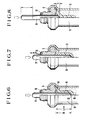
- Fig. 13 shows a construction of the counter flow preventing seal packing 15.
- the packing 15 has an annular projection 17 and an inwardly projected lip 19.
- the guide member 6 has a recess having an annular groove 18 corresponding to the annular projection 17.
- the projection 17 is engaged with the groove 18 as shown in Fig. 11 and a peripheral projection 16 is inwardly deformed by a predetermined oil pressure, thereby press the lip 19 against the piston 8.
- a predetermined oil pressure thereby press the lip 19 against the piston 8.
- a double O-ring seal device is provided in the guide member 6, .
- the seal device comprises a movable separator 20 slidably provided in a recess formed in the guide member 6 and mounted on the piston 8, a pair of O-rings 21 disposed on opposite sides of the separator 20, a fixed cover 22, and a peripheral flange 23 inwardly deformed by a predetermined oil pressure to fix the cover 22.
Applications Claiming Priority (6)
| Application Number | Priority Date | Filing Date | Title |
|---|---|---|---|
| JP134821/86 | 1986-06-12 | ||
| JP61134821A JPS62293325A (ja) | 1986-06-12 | 1986-06-12 | ワツクス型サ−モスタツト |
| JP61262744A JPS63120978A (ja) | 1986-11-06 | 1986-11-06 | ワツクス型サ−モスタツト |
| JP262744/86 | 1986-11-06 | ||
| JP62052883A JPS63219975A (ja) | 1987-03-10 | 1987-03-10 | ワツクス型サ−モスタツト |
| JP52883/87 | 1987-03-10 |
Publications (3)
| Publication Number | Publication Date |
|---|---|
| EP0249451A2 true EP0249451A2 (fr) | 1987-12-16 |
| EP0249451A3 EP0249451A3 (en) | 1989-02-01 |
| EP0249451B1 EP0249451B1 (fr) | 1992-12-02 |
Family
ID=27294779
Family Applications (1)
| Application Number | Title | Priority Date | Filing Date |
|---|---|---|---|
| EP87305116A Expired - Lifetime EP0249451B1 (fr) | 1986-06-12 | 1987-06-10 | Thermostat à boule de cire |
Country Status (6)
| Country | Link |
|---|---|
| US (2) | US4828167A (fr) |
| EP (1) | EP0249451B1 (fr) |
| KR (1) | KR900002541B1 (fr) |
| AU (2) | AU581125B2 (fr) |
| CA (1) | CA1284793C (fr) |
| DE (1) | DE3782857T2 (fr) |
Cited By (7)
| Publication number | Priority date | Publication date | Assignee | Title |
|---|---|---|---|---|
| EP0383249A1 (fr) * | 1989-02-15 | 1990-08-22 | KUZE, Yoshikazu | Thermostat à boulette de cire |
| EP0427460A1 (fr) * | 1989-11-04 | 1991-05-15 | Yoshikazu Kuze | Joint d'étanchéité pour thermostat |
| EP0566101A1 (fr) * | 1992-04-15 | 1993-10-20 | Yoshikazu Kuze | Servo-moteur thermique |
| AU707747B2 (en) * | 1997-04-11 | 1999-07-22 | Yoshikazu Kuze | Thermostat for an automotive engine cooling system |
| AT408584B (de) * | 1998-06-23 | 2002-01-25 | Ideal Standard | Thermostatdehnstoffelement |
| WO2018087747A1 (fr) * | 2016-11-13 | 2018-05-17 | M.A.P. Motorad Automotive Parts Ltd | Ensemble thermostat à compensation de pression |
| EP3612907A4 (fr) * | 2017-05-29 | 2021-04-14 | Kirpart Otomotiv Parçalari Sanayi Ve Ticaret A.S. | Actionneur avec diaphragme à résistance de pression augmentée |
Families Citing this family (16)
| Publication number | Priority date | Publication date | Assignee | Title |
|---|---|---|---|---|
| JP2512313B2 (ja) * | 1987-11-24 | 1996-07-03 | 義一 久世 | サ―モ・アクチュエ―タ |
| JPH04124473A (ja) * | 1990-09-13 | 1992-04-24 | Giichi Kuze | サーモ・アクチュエータ |
| JPH0811953B2 (ja) * | 1990-11-05 | 1996-02-07 | 義一 久世 | ラバ・シール直状管構成の軸封蛇腹とシール・バック構成のサーモ・アクチュエータ |
| FR2687448B1 (fr) * | 1992-02-14 | 1994-05-20 | Felix Michel | Soupape thermostatique de securite pour circuit de refroidissement hydraulique. |
| FR2739468B1 (fr) * | 1995-10-02 | 2003-03-07 | Inst Francais Du Petrole | Procede et dispositif de regulation de la temperature d'un fluide |
| AT410243B (de) | 1997-07-23 | 2003-03-25 | Tcg Unitech Ag | Mehrwegventil |
| FR2883995A1 (fr) * | 2005-04-04 | 2006-10-06 | Vernet Sa | Element thermostatique, notamment pour thermostat de circuit de refroidissement, et procede de fabrication d'un tel element |
| GB2495096A (en) * | 2011-09-28 | 2013-04-03 | Gm Global Tech Operations Inc | A thermostat with an auxiliary wax chamber for very cold starts |
| US9371988B2 (en) * | 2012-12-12 | 2016-06-21 | Scott E. Jewett | Candle assembly with retracting non-combustible wick |
| US9581074B2 (en) | 2014-12-22 | 2017-02-28 | Fca Us Llc | Engine thermostat with integrated coolant filter |
| US10024219B2 (en) * | 2015-11-19 | 2018-07-17 | Hyundai Motor Company | Engine system having coolant control valve |
| CN105422251A (zh) * | 2015-12-04 | 2016-03-23 | 重庆小康工业集团股份有限公司 | 发动机缸体冷却结构总成 |
| CN105332785A (zh) * | 2015-12-04 | 2016-02-17 | 重庆小康工业集团股份有限公司 | 发动机冷却用调温器总成 |
| CN107013735A (zh) * | 2016-12-15 | 2017-08-04 | 科派特汽车配件工贸联合股份公司 | 感温阀 |
| US10877498B2 (en) * | 2017-10-27 | 2020-12-29 | Brasscraft Manufacturing Company | Excess flow and thermal valve |
| CN111255556B (zh) * | 2018-12-03 | 2021-12-28 | 沃尔沃汽车公司 | 用于控制冷却液流动路径的节温器 |
Citations (5)
| Publication number | Priority date | Publication date | Assignee | Title |
|---|---|---|---|---|
| FR2333178A1 (fr) * | 1975-11-26 | 1977-06-24 | Braukmann Armaturen | Soupape thermostatique |
| US4288033A (en) * | 1978-07-17 | 1981-09-08 | Century Brass Products, Inc. | Control valve assembly |
| US4488680A (en) * | 1982-03-31 | 1984-12-18 | Aisin Seiki Kabushiki Kaisha | Thermally responsive valve device |
| US4595046A (en) * | 1982-12-11 | 1986-06-17 | Taisei Kogyo Co., Ltd. | Control apparatus for heat exchanger |
| US4679530A (en) * | 1985-02-19 | 1987-07-14 | Yoshikazu Kuze | Cooling system for an automobile engine |
Family Cites Families (15)
| Publication number | Priority date | Publication date | Assignee | Title |
|---|---|---|---|---|
| US244092A (en) * | 1881-07-12 | Hydraulic elevator | ||
| US2567479A (en) * | 1947-09-08 | 1951-09-11 | Phillips Petroleum Co | Polish rod stuffing box |
| US2694415A (en) * | 1950-12-23 | 1954-11-16 | Watts Regulator Co | Diaphragm construction for thermostats or motors |
| US2769597A (en) * | 1955-06-27 | 1956-11-06 | Bishop & Babcock Mfg Co | Thermostatic valve with solid actuator member |
| GB870363A (en) * | 1959-02-20 | 1961-06-14 | Gen Motors Ltd | Improvements in or relating to thermo-responsive power devices |
| FR1362891A (fr) * | 1962-07-12 | 1964-06-05 | Stabilus | Perfectionnements aux régulateurs de température thermostatiques destinés à équiper notamment le système de refroidissement de machines motrices à combustion |
| US3149455A (en) * | 1963-11-06 | 1964-09-22 | Ranco Inc | Condition responsive power elements |
| US3395580A (en) * | 1965-05-13 | 1968-08-06 | Yoshikaze Kuze | Thermostat |
| GB1196705A (en) * | 1968-04-09 | 1970-07-01 | Gen Motors Ltd | Thermo-Responsive Valves. |
| US3608912A (en) * | 1969-11-04 | 1971-09-28 | Xomox Corp | Sealing means for valve stems |
| JPS506021Y2 (fr) * | 1971-09-28 | 1975-02-20 | ||
| FR2255826A5 (en) * | 1973-12-21 | 1975-07-18 | Vernet Exploit Procedes | Expansion type thermostat for engine control - has wax and oil whose expansion coefficients are non-constant and constant |
| US4125696A (en) * | 1977-01-06 | 1978-11-14 | Pennwalt Corporation | Polymerization process using di-t-butyl diperoxycarbonate as a finishing catalyst |
| US4095470A (en) * | 1977-06-22 | 1978-06-20 | Robertshaw Controls Company | Thermal element and parts therefor and methods of making the same |
| US4187683A (en) * | 1978-06-12 | 1980-02-12 | Century Brass Products, Inc. | Thermal power element with safety lockup |
-
1987
- 1987-06-10 CA CA000539331A patent/CA1284793C/fr not_active Expired - Lifetime
- 1987-06-10 EP EP87305116A patent/EP0249451B1/fr not_active Expired - Lifetime
- 1987-06-10 DE DE8787305116T patent/DE3782857T2/de not_active Expired - Fee Related
- 1987-06-11 US US07/060,447 patent/US4828167A/en not_active Expired - Lifetime
- 1987-06-11 KR KR1019870005904A patent/KR900002541B1/ko not_active IP Right Cessation
- 1987-06-12 AU AU74175/87A patent/AU581125B2/en not_active Ceased
-
1988
- 1988-11-11 AU AU25077/88A patent/AU611966B2/en not_active Ceased
-
1989
- 1989-07-20 US US07/383,260 patent/US4948043A/en not_active Expired - Fee Related
Patent Citations (5)
| Publication number | Priority date | Publication date | Assignee | Title |
|---|---|---|---|---|
| FR2333178A1 (fr) * | 1975-11-26 | 1977-06-24 | Braukmann Armaturen | Soupape thermostatique |
| US4288033A (en) * | 1978-07-17 | 1981-09-08 | Century Brass Products, Inc. | Control valve assembly |
| US4488680A (en) * | 1982-03-31 | 1984-12-18 | Aisin Seiki Kabushiki Kaisha | Thermally responsive valve device |
| US4595046A (en) * | 1982-12-11 | 1986-06-17 | Taisei Kogyo Co., Ltd. | Control apparatus for heat exchanger |
| US4679530A (en) * | 1985-02-19 | 1987-07-14 | Yoshikazu Kuze | Cooling system for an automobile engine |
Cited By (7)
| Publication number | Priority date | Publication date | Assignee | Title |
|---|---|---|---|---|
| EP0383249A1 (fr) * | 1989-02-15 | 1990-08-22 | KUZE, Yoshikazu | Thermostat à boulette de cire |
| EP0427460A1 (fr) * | 1989-11-04 | 1991-05-15 | Yoshikazu Kuze | Joint d'étanchéité pour thermostat |
| EP0566101A1 (fr) * | 1992-04-15 | 1993-10-20 | Yoshikazu Kuze | Servo-moteur thermique |
| AU707747B2 (en) * | 1997-04-11 | 1999-07-22 | Yoshikazu Kuze | Thermostat for an automotive engine cooling system |
| AT408584B (de) * | 1998-06-23 | 2002-01-25 | Ideal Standard | Thermostatdehnstoffelement |
| WO2018087747A1 (fr) * | 2016-11-13 | 2018-05-17 | M.A.P. Motorad Automotive Parts Ltd | Ensemble thermostat à compensation de pression |
| EP3612907A4 (fr) * | 2017-05-29 | 2021-04-14 | Kirpart Otomotiv Parçalari Sanayi Ve Ticaret A.S. | Actionneur avec diaphragme à résistance de pression augmentée |
Also Published As
| Publication number | Publication date |
|---|---|
| EP0249451B1 (fr) | 1992-12-02 |
| DE3782857D1 (de) | 1993-01-14 |
| AU7417587A (en) | 1988-01-07 |
| KR900002541B1 (ko) | 1990-04-20 |
| KR880000726A (ko) | 1988-03-29 |
| DE3782857T2 (de) | 1993-05-13 |
| US4948043A (en) | 1990-08-14 |
| US4828167A (en) | 1989-05-09 |
| AU581125B2 (en) | 1989-02-09 |
| CA1284793C (fr) | 1991-06-11 |
| AU611966B2 (en) | 1991-06-27 |
| EP0249451A3 (en) | 1989-02-01 |
| AU2507788A (en) | 1989-02-09 |
Similar Documents
| Publication | Publication Date | Title |
|---|---|---|
| EP0249451B1 (fr) | Thermostat à boule de cire | |
| US5033865A (en) | Thermo-actuator | |
| US5067449A (en) | Fitted crankcase breather valve assembly | |
| RU2151309C1 (ru) | Термостат для системы охлаждения автомобильного двигателя | |
| US4257553A (en) | Valve construction and method of making the same | |
| US4317436A (en) | Valve stem seal | |
| JP3992753B2 (ja) | ガスケット | |
| US5509269A (en) | Thermo-actuator | |
| CA2050870C (fr) | Actionneur thermique | |
| US4165035A (en) | Thermally actuated valve for plural fluid sources | |
| US5205243A (en) | Crankcase breather having a fitted retainer for retaining a valved cup assembly | |
| EP0947676B1 (fr) | Système de refroidissement pour un moteur à combustion interne d' un véhicule | |
| US5083705A (en) | Wax-pellet thermostat | |
| US4280708A (en) | Sealing device for engine piston | |
| US4426036A (en) | Valve construction and method of making the same | |
| CA1155432A (fr) | Robinet a commande thermostatique | |
| US5129577A (en) | Sealing means for a thermostat | |
| GB2117494A (en) | A valved closure cap | |
| US5197440A (en) | Pressure-controlled valve device for engine radiator | |
| CA1324596C (fr) | Thermostat a pastille de cire | |
| US5515821A (en) | Valve spring retainer stem oil shield | |
| US7210846B2 (en) | Thermostat housing assembly | |
| US5809947A (en) | Piston valve | |
| JP2541494Y2 (ja) | 蒸気用減圧弁 | |
| JPS6141471Y2 (fr) |
Legal Events
| Date | Code | Title | Description |
|---|---|---|---|
| PUAI | Public reference made under article 153(3) epc to a published international application that has entered the european phase |
Free format text: ORIGINAL CODE: 0009012 |
|
| AK | Designated contracting states |
Kind code of ref document: A2 Designated state(s): DE FR GB IT |
|
| PUAL | Search report despatched |
Free format text: ORIGINAL CODE: 0009013 |
|
| AK | Designated contracting states |
Kind code of ref document: A3 Designated state(s): DE FR GB IT |
|
| 17P | Request for examination filed |
Effective date: 19890713 |
|
| 17Q | First examination report despatched |
Effective date: 19910228 |
|
| ITF | It: translation for a ep patent filed |
Owner name: SOCIETA' ITALIANA BREVETTI S.P.A. |
|
| GRAA | (expected) grant |
Free format text: ORIGINAL CODE: 0009210 |
|
| AK | Designated contracting states |
Kind code of ref document: B1 Designated state(s): DE FR GB IT |
|
| ET | Fr: translation filed | ||
| REF | Corresponds to: |
Ref document number: 3782857 Country of ref document: DE Date of ref document: 19930114 |
|
| PLBE | No opposition filed within time limit |
Free format text: ORIGINAL CODE: 0009261 |
|
| STAA | Information on the status of an ep patent application or granted ep patent |
Free format text: STATUS: NO OPPOSITION FILED WITHIN TIME LIMIT |
|
| 26N | No opposition filed | ||
| ITTA | It: last paid annual fee | ||
| PGFP | Annual fee paid to national office [announced via postgrant information from national office to epo] |
Ref country code: GB Payment date: 19960528 Year of fee payment: 10 |
|
| PGFP | Annual fee paid to national office [announced via postgrant information from national office to epo] |
Ref country code: FR Payment date: 19960628 Year of fee payment: 10 |
|
| PGFP | Annual fee paid to national office [announced via postgrant information from national office to epo] |
Ref country code: DE Payment date: 19960731 Year of fee payment: 10 |
|
| PG25 | Lapsed in a contracting state [announced via postgrant information from national office to epo] |
Ref country code: GB Free format text: LAPSE BECAUSE OF NON-PAYMENT OF DUE FEES Effective date: 19970610 |
|
| GBPC | Gb: european patent ceased through non-payment of renewal fee |
Effective date: 19970610 |
|
| PG25 | Lapsed in a contracting state [announced via postgrant information from national office to epo] |
Ref country code: FR Free format text: LAPSE BECAUSE OF NON-PAYMENT OF DUE FEES Effective date: 19980227 |
|
| PG25 | Lapsed in a contracting state [announced via postgrant information from national office to epo] |
Ref country code: DE Free format text: LAPSE BECAUSE OF NON-PAYMENT OF DUE FEES Effective date: 19980303 |
|
| REG | Reference to a national code |
Ref country code: FR Ref legal event code: ST |
|
| REG | Reference to a national code |
Ref country code: FR Ref legal event code: ST |
|
| PG25 | Lapsed in a contracting state [announced via postgrant information from national office to epo] |
Ref country code: IT Free format text: LAPSE BECAUSE OF NON-PAYMENT OF DUE FEES;WARNING: LAPSES OF ITALIAN PATENTS WITH EFFECTIVE DATE BEFORE 2007 MAY HAVE OCCURRED AT ANY TIME BEFORE 2007. THE CORRECT EFFECTIVE DATE MAY BE DIFFERENT FROM THE ONE RECORDED. Effective date: 20050610 |