US5205243A - Crankcase breather having a fitted retainer for retaining a valved cup assembly - Google Patents
Crankcase breather having a fitted retainer for retaining a valved cup assembly Download PDFInfo
- Publication number
- US5205243A US5205243A US07/857,742 US85774292A US5205243A US 5205243 A US5205243 A US 5205243A US 85774292 A US85774292 A US 85774292A US 5205243 A US5205243 A US 5205243A
- Authority
- US
- United States
- Prior art keywords
- crankcase
- opening
- breather
- retaining member
- cup
- Prior art date
- Legal status (The legal status is an assumption and is not a legal conclusion. Google has not performed a legal analysis and makes no representation as to the accuracy of the status listed.)
- Expired - Lifetime
Links
Images
Classifications
-
- F—MECHANICAL ENGINEERING; LIGHTING; HEATING; WEAPONS; BLASTING
- F01—MACHINES OR ENGINES IN GENERAL; ENGINE PLANTS IN GENERAL; STEAM ENGINES
- F01M—LUBRICATING OF MACHINES OR ENGINES IN GENERAL; LUBRICATING INTERNAL COMBUSTION ENGINES; CRANKCASE VENTILATING
- F01M13/00—Crankcase ventilating or breathing
- F01M13/0011—Breather valves
-
- F—MECHANICAL ENGINEERING; LIGHTING; HEATING; WEAPONS; BLASTING
- F01—MACHINES OR ENGINES IN GENERAL; ENGINE PLANTS IN GENERAL; STEAM ENGINES
- F01M—LUBRICATING OF MACHINES OR ENGINES IN GENERAL; LUBRICATING INTERNAL COMBUSTION ENGINES; CRANKCASE VENTILATING
- F01M11/00—Component parts, details or accessories, not provided for in, or of interest apart from, groups F01M1/00 - F01M9/00
- F01M11/04—Filling or draining lubricant of or from machines or engines
-
- F—MECHANICAL ENGINEERING; LIGHTING; HEATING; WEAPONS; BLASTING
- F01—MACHINES OR ENGINES IN GENERAL; ENGINE PLANTS IN GENERAL; STEAM ENGINES
- F01M—LUBRICATING OF MACHINES OR ENGINES IN GENERAL; LUBRICATING INTERNAL COMBUSTION ENGINES; CRANKCASE VENTILATING
- F01M13/00—Crankcase ventilating or breathing
- F01M13/02—Crankcase ventilating or breathing by means of additional source of positive or negative pressure
- F01M13/021—Crankcase ventilating or breathing by means of additional source of positive or negative pressure of negative pressure
- F01M13/022—Crankcase ventilating or breathing by means of additional source of positive or negative pressure of negative pressure using engine inlet suction
- F01M13/023—Control valves in suction conduit
Definitions
- the present invention relates generally to internal combustion engines, and more particularly, to a crankcase breather assembly for venting of crankcase gases.
- crankcase breather to rid the crankcase of pressures caused by blow-by gases escaping past worn piston rings and cylinder walls from the combustion chamber, by the downward force of the piston, and by expansion of the air in the crankcase from increasing heat. The buildup of pressure can eventually cause the oil seals to leak.
- a breather is installed in the crankcase.
- breather valves include a reed valve in which a flexible metal strip is positioned over an opening in the crankcase. The reed opens on the downward piston stroke when the pressure differential between the atmosphere and the crankcase is sufficient to overcome the spring tension of the reed.
- a second type of breather valve is a disc-type valve that is generally made of a lightweight metal or plastic and moves perpendicular to an opening in the crankcase. The disc is spring biased or gravity biased to a closed position and opens to cover the opening in response to pressure changes.
- a third type of breather valve is a molded flexible valve, commonly called a “mushroom” or “umbrella” valve.
- This valve has a center stem for attachment to a valve seat and covers a circular pattern of holes in the closed position. When crankcase pressure builds, the valve will flex upwardly to uncover the openings and vent the gases.
- a crankcase breather assembly wherein a plastic valve seat is press fit into a breather passage or opening in the crankcase.
- a flexible breather valve is secured to the valve seat for venting crankcase gases.
- the breather chamber is formed by an upstanding wall that extends upwardly from the top wall of the crankcase.
- the breather chamber is closed at the top by a removable cover plate and a corresponding sealing gasket.
- the breather chamber, valve seat, and valve are all incorporated into a molded plastic cup that is located in an opening in the crankcase.
- the flexible valve is attached to the bottom of the cup having the necessary valve openings therein.
- the cup is positioned within an opening in the crankcase, and a gasket is positioned over the molded flange at the top of the cup.
- a metal cover is then positioned over the gasket, and the entire assembly is held in place by several screws, which extend through the cover and crankcase.
- Some assemblies include a separate breather tube that is connected to the air cleaner assembly.
- the present invention provides an improved crankcase breather assembly for an internal combustion engine including a cup having a breather valve operatively disposed therein, wherein a retaining member is provided for engaging and retaining the cup as a single unit, which unit is then insertable into a breather opening formed in the crankcase such that an outer portion of the retainer frictionally engages a peripheral edge of the opening, whereby the retaining member is securely and sealingly retained within the opening.
- the invention provides, in one form thereof, a retaining member in the form of a resilient rubberlike vented cover having an inner grooved surface that elastically receives and seals an upper protruding lip portion of the cup for covering the cup and securely retaining the cup as a single unit.
- the retaining member may include a breather tube integral therewith.
- the invention provides, in one form thereof, a retaining member having a grooved outer surface, wherein the retaining member may be simply pushed into an opening in the crankcase until the grooved outer surface frictionally and sealingly receives a protruding peripheral edge of the opening such that the retaining member is locked therein.
- breather may be attached to the crankcase with fewer components and fewer labor intensive steps than conventional breather cup assemblies.
- breather may be inserted into a breather opening in the crankcase without the use of any special tools.
- breather may be reliably retained and sealed in the breather opening of the cylinder block without use of fasteners or secondary mechanical retention devices.
- Yet another advantage of the present invention is that the breather retaining member forms a tight seal with the breather opening wall to effectively prevent the flow of gases or liquids therebetween.
- the retaining member comprises a vented cover including an inner groove which serves as a stop flange for providing a physical stop when the retaining member is installed in the breather opening, thereby assuring proper depth of insertion of the retainer.
- Still another advantage of the present invention is that the retaining member sealingly covers the cup and includes a breather tube integral therewith.
- the present invention in one form thereof, provides an internal combustion engine having a crankcase and a crankcase interior.
- a crankcase breather assembly is provided for the venting of combustion gases from the crankcase interior.
- the assembly includes a breather opening in the crankcase for providing communication of gases out from the crankcase interior.
- a cup is provided in the opening and includes a valve for venting gases from the crankcase interior upon the condition of positive crankcase pressure.
- a retaining member is provided for engaging and retaining the cup and includes an outer groove that frictionally receives a peripheral edge of the opening, thereby retaining the retaining member in the opening.
- the present invention provides a retaining member which includes a locking portion disposed in the opening at least partially beyond the peripheral edge, thereby forming an interference fit therein to positively lock the retaining member within the opening.
- the invention further provides, in one form thereof, a method of assembling a crankcase breather assembly in an internal combustion engine having a crankcase interior.
- An opening is provided in the crankcase and includes a peripheral edge.
- a cup is provided including a valve disposed therein for venting gases from the crankcase interior upon the condition of positive crankcase pressure.
- a retaining member having a downwardly extending portion is attached over at least a portion of the cup to retain the cup and form a breather unit. The unit is then axially inserted into the opening such that a lower tip of the downwardly extending portion extends axially beyond the peripheral edge. Upon insertion, the downwardly extending portion is compressed inwardly by the peripheral edge to cause the lower tip to deform radially outwardly of the peripheral edge to lock the breather unit in place.
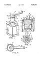
- FIG. 1 is a perspective view of a breather assembly and a portion of an engine crankcase in accordance with the principles of the present invention, wherein a breather is shown ready for insertion into an opening in the engine crankcase;
- FIG. 2 is an enlarged vertical sectional view of the breather assembly of FIG. 1 installed in the crankcase;
- FIG. 3 is an enlarged fragmentary view of FIG. 2, particularly showing the sealing arrangement between a portion of the retaining member and the peripheral edge of the crankcase opening and
- FIG. 4 is an enlarged bottom of the breather assembly of FIG. 1.
- crankcase 10 of an internal combustion engine
- crankcase 10 includes a generally horizontal top wall 12 and upstanding walls 14 and 16 integral with top wall 12 to circumscribe and define a crankcase interior 18 (FIG. 2).
- a breather opening 20 is provided in top wall 12 for permitting the venting of combustion gases therethrough to maintain a partial vacuum in crankcase interior 18.
- Opening 20 may be cast or machined but preferably machined for better control of tolerances.
- opening 20 may be of various sizes and shapes; however, for purposes of this discussion, opening 20 is generally annular in shape, as depicted in the drawings.
- Opening 20 includes an annular recess 22 and a laterally extending peripheral edge or flange 24.
- Flange 24 includes a mating surface 26, a vertical face 28, and a corner edge 30.
- a breather 32 In order to control and direct the flow of combustion gases out of crankcase interior 18, a breather 32 is provided.
- Breather 32 generally comprises a cup 34 and a retaining member 36 for engaging the cup and sealingly retaining the cup within opening 20.
- Cup 34 is preferably made from a low cost engineering grade thermoplastic such as nylon 66 plastic to provide accurate dimensions and a smooth flat surface for proper valve action and sealing.
- cup 34 comprises an upper cylindrical portion 38 including a peripheral lip 39 and a lower slightly tapered portion 40, wherein both portions 38 and 40 define a breather chamber 41 therein.
- An annular baffle element 42 which includes oil return openings 43, is supported by a flange 44 within cup 34 as shown in FIG. 2.
- Baffle 42 supports a filter element 46, which substantially fills the volume of breather chamber 41 within cylindrical portion 38.
- the lower end of lower tapered portion 40 includes a plurality of oil return openings 48, and a valve seat 53 having a plurality of small circular exhaust gas openings 50 and a central stem opening (not shown) which receives stem 52 of a flexible valve member 54.
- flexible breather valve 54 assumes an umbrella shape and initially sealingly engages the top surface of valve seat 53 such that valve 54 prevents fluid communication between crankcase interior 18 and breather chamber 41 .
- valve 54 prevents fluid communication between crankcase interior 18 and breather chamber 41 .
- the increased pressure forces flexible valve 54 to move upwardly from valve seat 53, to permit the flow of gases through openings 50.
- gravity causes valve 54 to return to its closed position.
- a retaining member 36 is provided and generally comprises a cover 55 and an integral breather tube 56 having an upturned end 58.
- Retaining member 36 is preferably in the form of a plug and may be made of a variety of elastic or resilient materials, especially natural or synthetic rubbers, and preferably a nitrile rubber.
- a conduit 60 is formed within tube 56 and is in communication with a vent opening 62 in cover 55 (FIG. 2).
- Tube 56 may be molded into a variety of configurations, depending upon where the tube is connected.
- tube 56 as shown in FIG. 1, is designed to be attached to the carburetor air inlet (not shown). However, tube 56 may alternatively be vented to the atmosphere.
- cover 55 includes a top surface 66 and a downwardly extending portion which locks the retainer in place and includes an outer diameter portion 68, a flange or chamfer 70 which engages and is stopped by mating surface 26 of flange 24 upon installation, a recessed or grooved portion 72, an outwardly extending portion 74, and a tapered portion 76.
- Cover 55 further includes an inner groove 78 which receives lip 39 of cup 34 such that retaining member 36 retains cup 34 to form single breather unit 32.
- retaining member 36 is attached to cup 34 by first elastically deforming the downwardly extending portion of cover 55 sufficiently to permit cover 55 to be slipped over the top of cup 34 and forced downwardly until inner groove 78 receives peripheral lip 34. At that point, cover 55 returns to its original position such that a seal 80 is formed, as shown in FIG. 3, to prevent the escape of gases between cup 34 and cover 55.
- the entire breather unit 32 is then inserted downwardly into opening 20 of crankcase 10 until chamfer 70 engages mating surface 26 to positively stop further downward movement of breather 32. It is noted that breather 32 may be inserted into opening 20 without the use of any special tools.
- the downwardly extending portion of retaining member 36 deforms as shown in FIG. 3, whereupon groove 72 receives peripheral edge 24 to form a fluid-tight seal therebetween.
- Portion 74 of retaining member 36 extends radially outwardly of corner edge 30 to form an interference fit therebetween to positively lock cover 55 in opening 20.
- retaining member 36 is shown as a cover for cup 34, it will be appreciated by those skilled in the art that the retaining member can be positioned anywhere along the outer surface of the breather cup for retaining the cup within the breather opening. In addition, the retaining member can be of any shape or size which would permit the locking portion of the retaining member to secure the cup in position.
Abstract
Description
Claims (15)
Priority Applications (3)
| Application Number | Priority Date | Filing Date | Title |
|---|---|---|---|
| US07/857,742 US5205243A (en) | 1992-03-26 | 1992-03-26 | Crankcase breather having a fitted retainer for retaining a valved cup assembly |
| EP93102735A EP0563565A1 (en) | 1992-03-26 | 1993-02-22 | Crankcase breather having a fitted retainer for retaining a valved cup assembly |
| CA002090580A CA2090580C (en) | 1992-03-26 | 1993-02-26 | Crankcase breather having a fitted retainer for retaining a valved cup assembly |
Applications Claiming Priority (1)
| Application Number | Priority Date | Filing Date | Title |
|---|---|---|---|
| US07/857,742 US5205243A (en) | 1992-03-26 | 1992-03-26 | Crankcase breather having a fitted retainer for retaining a valved cup assembly |
Publications (1)
| Publication Number | Publication Date |
|---|---|
| US5205243A true US5205243A (en) | 1993-04-27 |
Family
ID=25326654
Family Applications (1)
| Application Number | Title | Priority Date | Filing Date |
|---|---|---|---|
| US07/857,742 Expired - Lifetime US5205243A (en) | 1992-03-26 | 1992-03-26 | Crankcase breather having a fitted retainer for retaining a valved cup assembly |
Country Status (3)
| Country | Link |
|---|---|
| US (1) | US5205243A (en) |
| EP (1) | EP0563565A1 (en) |
| CA (1) | CA2090580C (en) |
Cited By (15)
| Publication number | Priority date | Publication date | Assignee | Title |
|---|---|---|---|---|
| US5881686A (en) * | 1997-09-08 | 1999-03-16 | D.L.S. Cycle Products, Inc. | Crankcase breather valve for engines with synchronous piston movement |
| US6105560A (en) * | 1999-06-08 | 2000-08-22 | Daidone; Phil | Baffled breather tube |
| US6167849B1 (en) * | 1998-06-24 | 2001-01-02 | Robert L. Wilson | Crankcase breather oil collector for motorcycles |
| US6263847B1 (en) | 1998-06-30 | 2001-07-24 | Harley-Davidson Motor Company Group, Inc. | Breather assembly for an internal combustion engine |
| US6883505B1 (en) | 2004-04-02 | 2005-04-26 | Midwest Motorcycle Supply | Rocker box assembly with reed valve |
| US20060000458A1 (en) * | 2004-06-30 | 2006-01-05 | Harley-Davidson Motor Company Group, Inc. | Breather assembly for an internal combustion engine |
| US20070186889A1 (en) * | 2006-02-13 | 2007-08-16 | Dana Corporation | Valve cover |
| US20070251225A1 (en) * | 2005-09-27 | 2007-11-01 | Doherty Timothy J | Method and apparatus for separating air and oil |
| US20070251512A1 (en) * | 2006-04-28 | 2007-11-01 | Caterpillar Inc. | Integrated check valve breather |
| US20080072883A1 (en) * | 2004-07-06 | 2008-03-27 | Brancato David M | Motorcycle crankcase ventilation reservoir and dissipator |
| US20090100811A1 (en) * | 2007-10-17 | 2009-04-23 | Scheckel Benjamin L | Inertial Gas-Liquid Separator with Constrictable and Expansible Nozzle Valve Sidewall |
| US20110204583A1 (en) * | 2010-02-24 | 2011-08-25 | Freudenberg-Nok General Partnership | Gasket Having Dual Bead Orientation On Rigid Carrier With Adjoining Gasket Material |
| US8893690B2 (en) | 2012-05-10 | 2014-11-25 | Caterpillar Inc. | Check valve for an engine breather assembly |
| JP2018091319A (en) * | 2016-12-01 | 2018-06-14 | 株式会社マーレ フィルターシステムズ | Drain nut attachment structure of synthetic resin-based cover |
| US10807468B1 (en) * | 2014-10-22 | 2020-10-20 | Hydro-Gear Limited Partnership | Drive apparatus |
Families Citing this family (1)
| Publication number | Priority date | Publication date | Assignee | Title |
|---|---|---|---|---|
| IT1310094B1 (en) * | 1999-07-09 | 2002-02-11 | Iveco Fiat | ENDOTHERMAL ENGINE PROVIDED WITH A GAS DEPURATION DEVICE BREATHER CRANKCASE. |
Citations (12)
| Publication number | Priority date | Publication date | Assignee | Title |
|---|---|---|---|---|
| US1706424A (en) * | 1927-08-22 | 1929-03-26 | Chrysler Corp | Crank-case ventilator |
| US2571893A (en) * | 1949-11-04 | 1951-10-16 | Gen Motors Corp | Submersible vent cap |
| US3051151A (en) * | 1961-08-28 | 1962-08-28 | Helwig Carl | Crankcase ventilator for automotive vehicles |
| US3087474A (en) * | 1961-10-31 | 1963-04-30 | Catha Ralph Harris | Oil vapor condenser |
| US3172399A (en) * | 1961-12-13 | 1965-03-09 | Walker Mfg Co | Exhaust system |
| US3359960A (en) * | 1964-12-21 | 1967-12-26 | Gen Motors Corp | Crankcase ventilation |
| US3766898A (en) * | 1971-10-21 | 1973-10-23 | Gen Motors Corp | Crankcase ventilation valve |
| US4169432A (en) * | 1977-03-31 | 1979-10-02 | Ford Motor Company | Integrated PCV valve and oil filler cap |
| US4579092A (en) * | 1980-09-17 | 1986-04-01 | Tecumseh Products Company | Crankcase breather mechanism |
| US4779601A (en) * | 1987-05-07 | 1988-10-25 | Dallman Alfred C | Automotive fuel saver device |
| US4926814A (en) * | 1989-07-12 | 1990-05-22 | Tecumseh Products Company | Crankcase breather and lubrication oil system for an internal combustion engine |
| US5067449A (en) * | 1991-04-12 | 1991-11-26 | Tecumseh Products Company | Fitted crankcase breather valve assembly |
Family Cites Families (2)
| Publication number | Priority date | Publication date | Assignee | Title |
|---|---|---|---|---|
| DE347770C (en) * | 1920-07-27 | 1922-01-24 | Otto Werke G M B H | Device for preventing the leakage from the crankcase of bicycle motors by maintaining a negative pressure by means of a valve located on the crankcase |
| US3088634A (en) * | 1960-01-27 | 1963-05-07 | Procter & Gamble | Tablet retainer cage |
-
1992
- 1992-03-26 US US07/857,742 patent/US5205243A/en not_active Expired - Lifetime
-
1993
- 1993-02-22 EP EP93102735A patent/EP0563565A1/en not_active Withdrawn
- 1993-02-26 CA CA002090580A patent/CA2090580C/en not_active Expired - Lifetime
Patent Citations (12)
| Publication number | Priority date | Publication date | Assignee | Title |
|---|---|---|---|---|
| US1706424A (en) * | 1927-08-22 | 1929-03-26 | Chrysler Corp | Crank-case ventilator |
| US2571893A (en) * | 1949-11-04 | 1951-10-16 | Gen Motors Corp | Submersible vent cap |
| US3051151A (en) * | 1961-08-28 | 1962-08-28 | Helwig Carl | Crankcase ventilator for automotive vehicles |
| US3087474A (en) * | 1961-10-31 | 1963-04-30 | Catha Ralph Harris | Oil vapor condenser |
| US3172399A (en) * | 1961-12-13 | 1965-03-09 | Walker Mfg Co | Exhaust system |
| US3359960A (en) * | 1964-12-21 | 1967-12-26 | Gen Motors Corp | Crankcase ventilation |
| US3766898A (en) * | 1971-10-21 | 1973-10-23 | Gen Motors Corp | Crankcase ventilation valve |
| US4169432A (en) * | 1977-03-31 | 1979-10-02 | Ford Motor Company | Integrated PCV valve and oil filler cap |
| US4579092A (en) * | 1980-09-17 | 1986-04-01 | Tecumseh Products Company | Crankcase breather mechanism |
| US4779601A (en) * | 1987-05-07 | 1988-10-25 | Dallman Alfred C | Automotive fuel saver device |
| US4926814A (en) * | 1989-07-12 | 1990-05-22 | Tecumseh Products Company | Crankcase breather and lubrication oil system for an internal combustion engine |
| US5067449A (en) * | 1991-04-12 | 1991-11-26 | Tecumseh Products Company | Fitted crankcase breather valve assembly |
Non-Patent Citations (2)
| Title |
|---|
| Tecumseh Products Company, Mechanic s Handbook, Form No. 692509, pp. 6 14, Publication Date Nov. 1985, Grafton, Wis. * |
| Tecumseh Products Company, Mechanic's Handbook, Form No. 692509, pp. 6-14, Publication Date Nov. 1985, Grafton, Wis. |
Cited By (19)
| Publication number | Priority date | Publication date | Assignee | Title |
|---|---|---|---|---|
| US5881686A (en) * | 1997-09-08 | 1999-03-16 | D.L.S. Cycle Products, Inc. | Crankcase breather valve for engines with synchronous piston movement |
| US6167849B1 (en) * | 1998-06-24 | 2001-01-02 | Robert L. Wilson | Crankcase breather oil collector for motorcycles |
| US6263847B1 (en) | 1998-06-30 | 2001-07-24 | Harley-Davidson Motor Company Group, Inc. | Breather assembly for an internal combustion engine |
| US6345613B1 (en) | 1998-06-30 | 2002-02-12 | Harley-Davidson Motor Company Group, Inc. | Breather assembly for an internal combustion engine |
| US6105560A (en) * | 1999-06-08 | 2000-08-22 | Daidone; Phil | Baffled breather tube |
| US6883505B1 (en) | 2004-04-02 | 2005-04-26 | Midwest Motorcycle Supply | Rocker box assembly with reed valve |
| US20060000458A1 (en) * | 2004-06-30 | 2006-01-05 | Harley-Davidson Motor Company Group, Inc. | Breather assembly for an internal combustion engine |
| US7063078B2 (en) | 2004-06-30 | 2006-06-20 | Harley-Davidson Motor Company Group, Inc. | Breather assembly for an internal combustion engine |
| US20080072883A1 (en) * | 2004-07-06 | 2008-03-27 | Brancato David M | Motorcycle crankcase ventilation reservoir and dissipator |
| US20070251225A1 (en) * | 2005-09-27 | 2007-11-01 | Doherty Timothy J | Method and apparatus for separating air and oil |
| US20070186889A1 (en) * | 2006-02-13 | 2007-08-16 | Dana Corporation | Valve cover |
| US7430999B2 (en) | 2006-02-13 | 2008-10-07 | Dana Automotive Systems Group, Llc | Valve cover |
| US20070251512A1 (en) * | 2006-04-28 | 2007-11-01 | Caterpillar Inc. | Integrated check valve breather |
| US20090100811A1 (en) * | 2007-10-17 | 2009-04-23 | Scheckel Benjamin L | Inertial Gas-Liquid Separator with Constrictable and Expansible Nozzle Valve Sidewall |
| US7857883B2 (en) * | 2007-10-17 | 2010-12-28 | Cummins Filtration Ip, Inc. | Inertial gas-liquid separator with constrictable and expansible nozzle valve sidewall |
| US20110204583A1 (en) * | 2010-02-24 | 2011-08-25 | Freudenberg-Nok General Partnership | Gasket Having Dual Bead Orientation On Rigid Carrier With Adjoining Gasket Material |
| US8893690B2 (en) | 2012-05-10 | 2014-11-25 | Caterpillar Inc. | Check valve for an engine breather assembly |
| US10807468B1 (en) * | 2014-10-22 | 2020-10-20 | Hydro-Gear Limited Partnership | Drive apparatus |
| JP2018091319A (en) * | 2016-12-01 | 2018-06-14 | 株式会社マーレ フィルターシステムズ | Drain nut attachment structure of synthetic resin-based cover |
Also Published As
| Publication number | Publication date |
|---|---|
| EP0563565A1 (en) | 1993-10-06 |
| CA2090580C (en) | 1995-06-13 |
Similar Documents
| Publication | Publication Date | Title |
|---|---|---|
| US5205243A (en) | Crankcase breather having a fitted retainer for retaining a valved cup assembly | |
| US5067449A (en) | Fitted crankcase breather valve assembly | |
| US5553869A (en) | Bonded valve stem seal with retainer tangs | |
| US5027784A (en) | PCV system with a check valve device | |
| US4401093A (en) | Oil fill/air breather cap with integral oil separator | |
| US4834037A (en) | Unitary molded plastic valve seal | |
| US5536018A (en) | Flexible spaghetti gasket seal with stiffening member | |
| US5511518A (en) | Sealing assembly with undercut groove | |
| US4896789A (en) | Anti-leak fuel cap liner | |
| EP0997674A2 (en) | Two-stage fuel tank vapor recovery vent valve and method of making same | |
| US4399783A (en) | Interference fit cylinder liner | |
| CN1159506A (en) | Improved two-piece valve stem seal | |
| US3480286A (en) | Valve stem seal | |
| US4133346A (en) | Pressure vacuum relief valve | |
| US4811960A (en) | Fixed valve stem oil seal | |
| US4637358A (en) | Spark plug cap apparatus | |
| MXPA04008102A (en) | Valve stem seal assembly with changeable cap. | |
| US2867482A (en) | Piston rings | |
| KR20110069004A (en) | Air breather valve assembly | |
| CA1138913A (en) | Valve stem seal | |
| US3620197A (en) | Crankcase ventilating means for submerged engine operation | |
| US2689533A (en) | Liquid pump | |
| US5193576A (en) | Pressure regulator | |
| US3771800A (en) | Valve stem seal | |
| US4848729A (en) | Valve seal |
Legal Events
| Date | Code | Title | Description |
|---|---|---|---|
| AS | Assignment |
Owner name: TECUMSEH PRODUCTS COMPANY A CORPORATION OF MI, MI Free format text: ASSIGNMENT OF ASSIGNORS INTEREST.;ASSIGNOR:BUCHHOLZ, BRIAN S.;REEL/FRAME:006069/0597 Effective date: 19920324 |
|
| STCF | Information on status: patent grant |
Free format text: PATENTED CASE |
|
| FEPP | Fee payment procedure |
Free format text: PAYOR NUMBER ASSIGNED (ORIGINAL EVENT CODE: ASPN); ENTITY STATUS OF PATENT OWNER: LARGE ENTITY |
|
| FPAY | Fee payment |
Year of fee payment: 4 |
|
| FPAY | Fee payment |
Year of fee payment: 8 |
|
| FPAY | Fee payment |
Year of fee payment: 12 |
|
| AS | Assignment |
Owner name: JPMORGAN CHASE BANK, N.A.,MICHIGAN Free format text: SECURITY AGREEMENT;ASSIGNOR:TECUMSEH PRODUCTS COMPANY;REEL/FRAME:016641/0380 Effective date: 20050930 Owner name: JPMORGAN CHASE BANK, N.A., MICHIGAN Free format text: SECURITY AGREEMENT;ASSIGNOR:TECUMSEH PRODUCTS COMPANY;REEL/FRAME:016641/0380 Effective date: 20050930 |
|
| AS | Assignment |
Owner name: CITICORP USA, INC.,NEW YORK Free format text: SECURITY INTEREST;ASSIGNORS:TECUMSEH PRODUCTS COMPANY;CONVERGENT TECHNOLOGIES INTERNATIONAL, INC.;TECUMSEH TRADING COMPANY;AND OTHERS;REEL/FRAME:017606/0644 Effective date: 20060206 Owner name: CITICORP USA, INC., NEW YORK Free format text: SECURITY INTEREST;ASSIGNORS:TECUMSEH PRODUCTS COMPANY;CONVERGENT TECHNOLOGIES INTERNATIONAL, INC.;TECUMSEH TRADING COMPANY;AND OTHERS;REEL/FRAME:017606/0644 Effective date: 20060206 |
|
| AS | Assignment |
Owner name: TECUMSEH POWER COMPANY, CALIFORNIA Free format text: ASSIGNMENT OF ASSIGNORS INTEREST;ASSIGNOR:TECUMSEH PRODUCTS COMPANY;REEL/FRAME:020196/0612 Effective date: 20071109 |
|
| AS | Assignment |
Owner name: TECUMSEH PRODUCTS COMPANY, MICHIGAN Free format text: PARTIAL RELEASE OF SECURITY INTEREST;ASSIGNOR:CITICORP NORTH AMERICA, INC.;REEL/FRAME:020417/0052 Effective date: 20080111 Owner name: EUROMOTOR, INC., MICHIGAN Free format text: PARTIAL RELEASE OF SECURITY INTEREST;ASSIGNOR:CITICORP NORTH AMERICA, INC.;REEL/FRAME:020417/0052 Effective date: 20080111 Owner name: MANUFACTURING DATA SYSTEMS, INC., MICHIGAN Free format text: PARTIAL RELEASE OF SECURITY INTEREST;ASSIGNOR:CITICORP NORTH AMERICA, INC.;REEL/FRAME:020417/0052 Effective date: 20080111 Owner name: M.P. PUMPS, INC., MICHIGAN Free format text: PARTIAL RELEASE OF SECURITY INTEREST;ASSIGNOR:CITICORP NORTH AMERICA, INC.;REEL/FRAME:020417/0052 Effective date: 20080111 Owner name: LITTLE GIANT PUMP COMPANY, OKLAHOMA Free format text: PARTIAL RELEASE OF SECURITY INTEREST;ASSIGNOR:CITICORP NORTH AMERICA, INC.;REEL/FRAME:020417/0052 Effective date: 20080111 Owner name: EVERGY, INC., MICHIGAN Free format text: PARTIAL RELEASE OF SECURITY INTEREST;ASSIGNOR:CITICORP NORTH AMERICA, INC.;REEL/FRAME:020417/0052 Effective date: 20080111 Owner name: CONVERGENT TECHNOLOGIES INTERNATIONAL, INC., MICHI Free format text: PARTIAL RELEASE OF SECURITY INTEREST;ASSIGNOR:CITICORP NORTH AMERICA, INC.;REEL/FRAME:020417/0052 Effective date: 20080111 Owner name: TECUMSEH PUMP COMPANY, MICHIGAN Free format text: PARTIAL RELEASE OF SECURITY INTEREST;ASSIGNOR:CITICORP NORTH AMERICA, INC.;REEL/FRAME:020417/0052 Effective date: 20080111 Owner name: TECUMSEH COMPRESSOR COMPANY, MICHIGAN Free format text: PARTIAL RELEASE OF SECURITY INTEREST;ASSIGNOR:CITICORP NORTH AMERICA, INC.;REEL/FRAME:020417/0052 Effective date: 20080111 Owner name: TECUMSEH DO BRASIL USA, LLC, MICHIGAN Free format text: PARTIAL RELEASE OF SECURITY INTEREST;ASSIGNOR:CITICORP NORTH AMERICA, INC.;REEL/FRAME:020417/0052 Effective date: 20080111 Owner name: TECUMSEH CANADA HOLDING COMPANY, MICHIGAN Free format text: PARTIAL RELEASE OF SECURITY INTEREST;ASSIGNOR:CITICORP NORTH AMERICA, INC.;REEL/FRAME:020417/0052 Effective date: 20080111 Owner name: HAYTON PROPERTY COMPANY, LLC, MICHIGAN Free format text: PARTIAL RELEASE OF SECURITY INTEREST;ASSIGNOR:CITICORP NORTH AMERICA, INC.;REEL/FRAME:020417/0052 Effective date: 20080111 Owner name: TECUMSEH AUTO, INC., FORMERLY FASCO INDUSTRIES, IN Free format text: PARTIAL RELEASE OF SECURITY INTEREST;ASSIGNOR:CITICORP NORTH AMERICA, INC.;REEL/FRAME:020417/0052 Effective date: 20080111 Owner name: VON WEISE GEAR COMPANY, MICHIGAN Free format text: PARTIAL RELEASE OF SECURITY INTEREST;ASSIGNOR:CITICORP NORTH AMERICA, INC.;REEL/FRAME:020417/0052 Effective date: 20080111 Owner name: TECUMSEH TRADING COMPANY, MICHIGAN Free format text: PARTIAL RELEASE OF SECURITY INTEREST;ASSIGNOR:CITICORP NORTH AMERICA, INC.;REEL/FRAME:020417/0052 Effective date: 20080111 Owner name: TECUMSEH POWER COMPANY, WISCONSIN Free format text: PARTIAL RELEASE OF SECURITY INTEREST;ASSIGNOR:CITICORP NORTH AMERICA, INC.;REEL/FRAME:020417/0052 Effective date: 20080111 |
|
| AS | Assignment |
Owner name: WELLS FARGO FOOTHILL, LLC, CALIFORNIA Free format text: SECURITY AGREEMENT;ASSIGNOR:TECUMSEH POWER COMPANY;REEL/FRAME:020431/0127 Effective date: 20071221 |
|
| AS | Assignment |
Owner name: TECUMSEH PRODUCTS COMPANY, MICHIGAN Free format text: PARTIAL RELEASE OF SECURITY INTEREST;ASSIGNOR:JPMORGAN CHASE BANK, N.A.;REEL/FRAME:020582/0023 Effective date: 20080115 Owner name: TECUMSEH INVESTMENTS, INC., MICHIGAN Free format text: PARTIAL RELEASE OF SECURITY INTEREST;ASSIGNOR:JPMORGAN CHASE BANK, N.A.;REEL/FRAME:020582/0023 Effective date: 20080115 Owner name: DOUGLAS HOLDINGS, INC., MICHIGAN Free format text: PARTIAL RELEASE OF SECURITY INTEREST;ASSIGNOR:JPMORGAN CHASE BANK, N.A.;REEL/FRAME:020582/0023 Effective date: 20080115 Owner name: CONVERGENT TECHNOLOGIES INTERNATIONAL, INC., MICHI Free format text: PARTIAL RELEASE OF SECURITY INTEREST;ASSIGNOR:JPMORGAN CHASE BANK, N.A.;REEL/FRAME:020582/0023 Effective date: 20080115 Owner name: EUROMOTOR, INC., MICHIGAN Free format text: PARTIAL RELEASE OF SECURITY INTEREST;ASSIGNOR:JPMORGAN CHASE BANK, N.A.;REEL/FRAME:020582/0023 Effective date: 20080115 Owner name: M.P. PUMPS, INC., MICHIGAN Free format text: PARTIAL RELEASE OF SECURITY INTEREST;ASSIGNOR:JPMORGAN CHASE BANK, N.A.;REEL/FRAME:020582/0023 Effective date: 20080115 Owner name: MANUFACTURING DATA SYSTEMS, INC., MICHIGAN Free format text: PARTIAL RELEASE OF SECURITY INTEREST;ASSIGNOR:JPMORGAN CHASE BANK, N.A.;REEL/FRAME:020582/0023 Effective date: 20080115 Owner name: TECUMSEH DO BRASIL USA, LLC, MICHIGAN Free format text: PARTIAL RELEASE OF SECURITY INTEREST;ASSIGNOR:JPMORGAN CHASE BANK, N.A.;REEL/FRAME:020582/0023 Effective date: 20080115 Owner name: TECUMSEH POWER COMPANY, WISCONSIN Free format text: PARTIAL RELEASE OF SECURITY INTEREST;ASSIGNOR:JPMORGAN CHASE BANK, N.A.;REEL/FRAME:020582/0023 Effective date: 20080115 Owner name: LITTLE GIANT PUMP COMPANY, OKLAHOMA Free format text: PARTIAL RELEASE OF SECURITY INTEREST;ASSIGNOR:JPMORGAN CHASE BANK, N.A.;REEL/FRAME:020582/0023 Effective date: 20080115 Owner name: HAYTON PROPERTY COMPANY, LLC, MICHIGAN Free format text: PARTIAL RELEASE OF SECURITY INTEREST;ASSIGNOR:JPMORGAN CHASE BANK, N.A.;REEL/FRAME:020582/0023 Effective date: 20080115 Owner name: TECUMSEH COMPRESSOR COMPANY, MICHIGAN Free format text: PARTIAL RELEASE OF SECURITY INTEREST;ASSIGNOR:JPMORGAN CHASE BANK, N.A.;REEL/FRAME:020582/0023 Effective date: 20080115 Owner name: TECUMSEH PUMP COMPANY, MICHIGAN Free format text: PARTIAL RELEASE OF SECURITY INTEREST;ASSIGNOR:JPMORGAN CHASE BANK, N.A.;REEL/FRAME:020582/0023 Effective date: 20080115 Owner name: VON WEISE GEAR COMPANY, MICHIGAN Free format text: PARTIAL RELEASE OF SECURITY INTEREST;ASSIGNOR:JPMORGAN CHASE BANK, N.A.;REEL/FRAME:020582/0023 Effective date: 20080115 Owner name: TECUMSEH AUTO, INC., FORMERLY FASCO INDUSTRIES, IN Free format text: PARTIAL RELEASE OF SECURITY INTEREST;ASSIGNOR:JPMORGAN CHASE BANK, N.A.;REEL/FRAME:020582/0023 Effective date: 20080115 Owner name: EVERGY, INC., MICHIGAN Free format text: PARTIAL RELEASE OF SECURITY INTEREST;ASSIGNOR:JPMORGAN CHASE BANK, N.A.;REEL/FRAME:020582/0023 Effective date: 20080115 Owner name: TECUMSEH CANADA HOLDING COMPANY, MICHIGAN Free format text: PARTIAL RELEASE OF SECURITY INTEREST;ASSIGNOR:JPMORGAN CHASE BANK, N.A.;REEL/FRAME:020582/0023 Effective date: 20080115 |