EP0249372A2 - Fiber reinforced braided ski core and method and apparatus for making same - Google Patents
Fiber reinforced braided ski core and method and apparatus for making same Download PDFInfo
- Publication number
- EP0249372A2 EP0249372A2 EP87304823A EP87304823A EP0249372A2 EP 0249372 A2 EP0249372 A2 EP 0249372A2 EP 87304823 A EP87304823 A EP 87304823A EP 87304823 A EP87304823 A EP 87304823A EP 0249372 A2 EP0249372 A2 EP 0249372A2
- Authority
- EP
- European Patent Office
- Prior art keywords
- core
- strands
- ski
- wrapped
- along
- Prior art date
- Legal status (The legal status is an assumption and is not a legal conclusion. Google has not performed a legal analysis and makes no representation as to the accuracy of the status listed.)
- Granted
Links
- 239000000835 fiber Substances 0.000 title claims abstract description 32
- 238000000034 method Methods 0.000 title claims description 18
- 239000011152 fibreglass Substances 0.000 claims abstract description 53
- 238000009954 braiding Methods 0.000 claims abstract description 45
- 239000000463 material Substances 0.000 claims abstract description 12
- OKTJSMMVPCPJKN-UHFFFAOYSA-N Carbon Chemical compound [C] OKTJSMMVPCPJKN-UHFFFAOYSA-N 0.000 claims description 3
- 229920000271 Kevlar® Polymers 0.000 claims description 3
- 229910052799 carbon Inorganic materials 0.000 claims description 3
- 239000004761 kevlar Substances 0.000 claims description 3
- 229920000728 polyester Polymers 0.000 claims description 2
- 239000012783 reinforcing fiber Substances 0.000 claims 6
- 230000002787 reinforcement Effects 0.000 abstract description 5
- 238000004519 manufacturing process Methods 0.000 description 8
- 239000011521 glass Substances 0.000 description 3
- 239000002184 metal Substances 0.000 description 3
- 239000004033 plastic Substances 0.000 description 3
- 229920005989 resin Polymers 0.000 description 3
- 239000011347 resin Substances 0.000 description 3
- 238000010276 construction Methods 0.000 description 2
- 239000002657 fibrous material Substances 0.000 description 2
- 238000005470 impregnation Methods 0.000 description 2
- 239000004593 Epoxy Substances 0.000 description 1
- 241000220010 Rhode Species 0.000 description 1
- 230000002411 adverse Effects 0.000 description 1
- 239000002537 cosmetic Substances 0.000 description 1
- 238000005520 cutting process Methods 0.000 description 1
- 230000003247 decreasing effect Effects 0.000 description 1
- 239000003822 epoxy resin Substances 0.000 description 1
- 238000009787 hand lay-up Methods 0.000 description 1
- 230000002093 peripheral effect Effects 0.000 description 1
- 229920000647 polyepoxide Polymers 0.000 description 1
- 238000003908 quality control method Methods 0.000 description 1
Images


Classifications
-
- D—TEXTILES; PAPER
- D04—BRAIDING; LACE-MAKING; KNITTING; TRIMMINGS; NON-WOVEN FABRICS
- D04C—BRAIDING OR MANUFACTURE OF LACE, INCLUDING BOBBIN-NET OR CARBONISED LACE; BRAIDING MACHINES; BRAID; LACE
- D04C1/00—Braid or lace, e.g. pillow-lace; Processes for the manufacture thereof
- D04C1/06—Braid or lace serving particular purposes
-
- A—HUMAN NECESSITIES
- A63—SPORTS; GAMES; AMUSEMENTS
- A63C—SKATES; SKIS; ROLLER SKATES; DESIGN OR LAYOUT OF COURTS, RINKS OR THE LIKE
- A63C5/00—Skis or snowboards
- A63C5/12—Making thereof; Selection of particular materials
-
- B—PERFORMING OPERATIONS; TRANSPORTING
- B29—WORKING OF PLASTICS; WORKING OF SUBSTANCES IN A PLASTIC STATE IN GENERAL
- B29C—SHAPING OR JOINING OF PLASTICS; SHAPING OF MATERIAL IN A PLASTIC STATE, NOT OTHERWISE PROVIDED FOR; AFTER-TREATMENT OF THE SHAPED PRODUCTS, e.g. REPAIRING
- B29C53/00—Shaping by bending, folding, twisting, straightening or flattening; Apparatus therefor
- B29C53/56—Winding and joining, e.g. winding spirally
- B29C53/58—Winding and joining, e.g. winding spirally helically
- B29C53/60—Winding and joining, e.g. winding spirally helically using internal forming surfaces, e.g. mandrels
- B29C53/62—Winding and joining, e.g. winding spirally helically using internal forming surfaces, e.g. mandrels rotatable about the winding axis
- B29C53/66—Winding and joining, e.g. winding spirally helically using internal forming surfaces, e.g. mandrels rotatable about the winding axis with axially movable winding feed member, e.g. lathe type winding
- B29C53/665—Coordinating the movements of the winding feed member and the mandrel
-
- B—PERFORMING OPERATIONS; TRANSPORTING
- B29—WORKING OF PLASTICS; WORKING OF SUBSTANCES IN A PLASTIC STATE IN GENERAL
- B29C—SHAPING OR JOINING OF PLASTICS; SHAPING OF MATERIAL IN A PLASTIC STATE, NOT OTHERWISE PROVIDED FOR; AFTER-TREATMENT OF THE SHAPED PRODUCTS, e.g. REPAIRING
- B29C53/00—Shaping by bending, folding, twisting, straightening or flattening; Apparatus therefor
- B29C53/80—Component parts, details or accessories; Auxiliary operations
- B29C53/8008—Component parts, details or accessories; Auxiliary operations specially adapted for winding and joining
- B29C53/8016—Storing, feeding or applying winding materials, e.g. reels, thread guides, tensioners
-
- B—PERFORMING OPERATIONS; TRANSPORTING
- B29—WORKING OF PLASTICS; WORKING OF SUBSTANCES IN A PLASTIC STATE IN GENERAL
- B29C—SHAPING OR JOINING OF PLASTICS; SHAPING OF MATERIAL IN A PLASTIC STATE, NOT OTHERWISE PROVIDED FOR; AFTER-TREATMENT OF THE SHAPED PRODUCTS, e.g. REPAIRING
- B29C53/00—Shaping by bending, folding, twisting, straightening or flattening; Apparatus therefor
- B29C53/80—Component parts, details or accessories; Auxiliary operations
- B29C53/8008—Component parts, details or accessories; Auxiliary operations specially adapted for winding and joining
- B29C53/805—Applying axial reinforcements
-
- B—PERFORMING OPERATIONS; TRANSPORTING
- B29—WORKING OF PLASTICS; WORKING OF SUBSTANCES IN A PLASTIC STATE IN GENERAL
- B29C—SHAPING OR JOINING OF PLASTICS; SHAPING OF MATERIAL IN A PLASTIC STATE, NOT OTHERWISE PROVIDED FOR; AFTER-TREATMENT OF THE SHAPED PRODUCTS, e.g. REPAIRING
- B29C70/00—Shaping composites, i.e. plastics material comprising reinforcements, fillers or preformed parts, e.g. inserts
- B29C70/04—Shaping composites, i.e. plastics material comprising reinforcements, fillers or preformed parts, e.g. inserts comprising reinforcements only, e.g. self-reinforcing plastics
- B29C70/06—Fibrous reinforcements only
- B29C70/10—Fibrous reinforcements only characterised by the structure of fibrous reinforcements, e.g. hollow fibres
- B29C70/16—Fibrous reinforcements only characterised by the structure of fibrous reinforcements, e.g. hollow fibres using fibres of substantial or continuous length
- B29C70/22—Fibrous reinforcements only characterised by the structure of fibrous reinforcements, e.g. hollow fibres using fibres of substantial or continuous length oriented in at least two directions forming a two dimensional structure
- B29C70/222—Fibrous reinforcements only characterised by the structure of fibrous reinforcements, e.g. hollow fibres using fibres of substantial or continuous length oriented in at least two directions forming a two dimensional structure the structure being shaped to form a three dimensional configuration
-
- B—PERFORMING OPERATIONS; TRANSPORTING
- B29—WORKING OF PLASTICS; WORKING OF SUBSTANCES IN A PLASTIC STATE IN GENERAL
- B29C—SHAPING OR JOINING OF PLASTICS; SHAPING OF MATERIAL IN A PLASTIC STATE, NOT OTHERWISE PROVIDED FOR; AFTER-TREATMENT OF THE SHAPED PRODUCTS, e.g. REPAIRING
- B29C70/00—Shaping composites, i.e. plastics material comprising reinforcements, fillers or preformed parts, e.g. inserts
- B29C70/68—Shaping composites, i.e. plastics material comprising reinforcements, fillers or preformed parts, e.g. inserts by incorporating or moulding on preformed parts, e.g. inserts or layers, e.g. foam blocks
- B29C70/86—Incorporated in coherent impregnated reinforcing layers, e.g. by winding
- B29C70/865—Incorporated in coherent impregnated reinforcing layers, e.g. by winding completely encapsulated
-
- D—TEXTILES; PAPER
- D04—BRAIDING; LACE-MAKING; KNITTING; TRIMMINGS; NON-WOVEN FABRICS
- D04C—BRAIDING OR MANUFACTURE OF LACE, INCLUDING BOBBIN-NET OR CARBONISED LACE; BRAIDING MACHINES; BRAID; LACE
- D04C3/00—Braiding or lacing machines
- D04C3/40—Braiding or lacing machines for making tubular braids by circulating strand supplies around braiding centre at equal distances
-
- D—TEXTILES; PAPER
- D04—BRAIDING; LACE-MAKING; KNITTING; TRIMMINGS; NON-WOVEN FABRICS
- D04C—BRAIDING OR MANUFACTURE OF LACE, INCLUDING BOBBIN-NET OR CARBONISED LACE; BRAIDING MACHINES; BRAID; LACE
- D04C3/00—Braiding or lacing machines
- D04C3/48—Auxiliary devices
-
- B—PERFORMING OPERATIONS; TRANSPORTING
- B29—WORKING OF PLASTICS; WORKING OF SUBSTANCES IN A PLASTIC STATE IN GENERAL
- B29K—INDEXING SCHEME ASSOCIATED WITH SUBCLASSES B29B, B29C OR B29D, RELATING TO MOULDING MATERIALS OR TO MATERIALS FOR MOULDS, REINFORCEMENTS, FILLERS OR PREFORMED PARTS, e.g. INSERTS
- B29K2105/00—Condition, form or state of moulded material or of the material to be shaped
- B29K2105/06—Condition, form or state of moulded material or of the material to be shaped containing reinforcements, fillers or inserts
- B29K2105/08—Condition, form or state of moulded material or of the material to be shaped containing reinforcements, fillers or inserts of continuous length, e.g. cords, rovings, mats, fabrics, strands or yarns
- B29K2105/0809—Fabrics
- B29K2105/0827—Braided fabrics
-
- B—PERFORMING OPERATIONS; TRANSPORTING
- B29—WORKING OF PLASTICS; WORKING OF SUBSTANCES IN A PLASTIC STATE IN GENERAL
- B29L—INDEXING SCHEME ASSOCIATED WITH SUBCLASS B29C, RELATING TO PARTICULAR ARTICLES
- B29L2031/00—Other particular articles
- B29L2031/52—Sports equipment ; Games; Articles for amusement; Toys
- B29L2031/5263—Skis
-
- D—TEXTILES; PAPER
- D10—INDEXING SCHEME ASSOCIATED WITH SUBLASSES OF SECTION D, RELATING TO TEXTILES
- D10B—INDEXING SCHEME ASSOCIATED WITH SUBLASSES OF SECTION D, RELATING TO TEXTILES
- D10B2403/00—Details of fabric structure established in the fabric forming process
- D10B2403/02—Cross-sectional features
- D10B2403/024—Fabric incorporating additional compounds
- D10B2403/0241—Fabric incorporating additional compounds enhancing mechanical properties
- D10B2403/02411—Fabric incorporating additional compounds enhancing mechanical properties with a single array of unbent yarn, e.g. unidirectional reinforcement fabrics
-
- D—TEXTILES; PAPER
- D10—INDEXING SCHEME ASSOCIATED WITH SUBLASSES OF SECTION D, RELATING TO TEXTILES
- D10B—INDEXING SCHEME ASSOCIATED WITH SUBLASSES OF SECTION D, RELATING TO TEXTILES
- D10B2505/00—Industrial
- D10B2505/02—Reinforcing materials; Prepregs
-
- Y—GENERAL TAGGING OF NEW TECHNOLOGICAL DEVELOPMENTS; GENERAL TAGGING OF CROSS-SECTIONAL TECHNOLOGIES SPANNING OVER SEVERAL SECTIONS OF THE IPC; TECHNICAL SUBJECTS COVERED BY FORMER USPC CROSS-REFERENCE ART COLLECTIONS [XRACs] AND DIGESTS
- Y10—TECHNICAL SUBJECTS COVERED BY FORMER USPC
- Y10T—TECHNICAL SUBJECTS COVERED BY FORMER US CLASSIFICATION
- Y10T428/00—Stock material or miscellaneous articles
- Y10T428/24—Structurally defined web or sheet [e.g., overall dimension, etc.]
- Y10T428/24058—Structurally defined web or sheet [e.g., overall dimension, etc.] including grain, strips, or filamentary elements in respective layers or components in angular relation
- Y10T428/24074—Strand or strand-portions
- Y10T428/24091—Strand or strand-portions with additional layer[s]
- Y10T428/24099—On each side of strands or strand-portions
- Y10T428/24107—On each side of strands or strand-portions including mechanically interengaged strands, strand-portions or strand-like strips
-
- Y—GENERAL TAGGING OF NEW TECHNOLOGICAL DEVELOPMENTS; GENERAL TAGGING OF CROSS-SECTIONAL TECHNOLOGIES SPANNING OVER SEVERAL SECTIONS OF THE IPC; TECHNICAL SUBJECTS COVERED BY FORMER USPC CROSS-REFERENCE ART COLLECTIONS [XRACs] AND DIGESTS
- Y10—TECHNICAL SUBJECTS COVERED BY FORMER USPC
- Y10T—TECHNICAL SUBJECTS COVERED BY FORMER US CLASSIFICATION
- Y10T428/00—Stock material or miscellaneous articles
- Y10T428/24—Structurally defined web or sheet [e.g., overall dimension, etc.]
- Y10T428/24058—Structurally defined web or sheet [e.g., overall dimension, etc.] including grain, strips, or filamentary elements in respective layers or components in angular relation
- Y10T428/24074—Strand or strand-portions
- Y10T428/24116—Oblique to direction of web
-
- Y—GENERAL TAGGING OF NEW TECHNOLOGICAL DEVELOPMENTS; GENERAL TAGGING OF CROSS-SECTIONAL TECHNOLOGIES SPANNING OVER SEVERAL SECTIONS OF THE IPC; TECHNICAL SUBJECTS COVERED BY FORMER USPC CROSS-REFERENCE ART COLLECTIONS [XRACs] AND DIGESTS
- Y10—TECHNICAL SUBJECTS COVERED BY FORMER USPC
- Y10T—TECHNICAL SUBJECTS COVERED BY FORMER US CLASSIFICATION
- Y10T428/00—Stock material or miscellaneous articles
- Y10T428/24—Structurally defined web or sheet [e.g., overall dimension, etc.]
- Y10T428/24058—Structurally defined web or sheet [e.g., overall dimension, etc.] including grain, strips, or filamentary elements in respective layers or components in angular relation
- Y10T428/24124—Fibers
-
- Y—GENERAL TAGGING OF NEW TECHNOLOGICAL DEVELOPMENTS; GENERAL TAGGING OF CROSS-SECTIONAL TECHNOLOGIES SPANNING OVER SEVERAL SECTIONS OF THE IPC; TECHNICAL SUBJECTS COVERED BY FORMER USPC CROSS-REFERENCE ART COLLECTIONS [XRACs] AND DIGESTS
- Y10—TECHNICAL SUBJECTS COVERED BY FORMER USPC
- Y10T—TECHNICAL SUBJECTS COVERED BY FORMER US CLASSIFICATION
- Y10T428/00—Stock material or miscellaneous articles
- Y10T428/24—Structurally defined web or sheet [e.g., overall dimension, etc.]
- Y10T428/24174—Structurally defined web or sheet [e.g., overall dimension, etc.] including sheet or component perpendicular to plane of web or sheet
Definitions
- the present invention relates to fiber reinforced skis in general and in particular to skis formed by the wet wrap or torsion box process wherein a wooden or foamed plastic core is wrapped in a fiber reinforced sheet impregnated with resin, "cooked” and cured under pressure in a mold with a base assembly.
- the invention comprises a unique braided fiber reinforced "sock" covering for a ski core which includes strands of reinforcement oriented at an angle to the longitudinal direction of the core and braided directly thereon. Longitudinally extending strands of reinforcement may be intertwined with the braided strands and other longitudinal strands of material may be positioned on the top or bottom surface of the ski core between the core and the braided reinforcement.
- fiber reinforcement is meant to include any high-modulus fibrous material such as glass, "Kevlar", carbon, metal wire, polypolyester, etc. suitable for the production of skis.
- a method and apparatus for manufacturing the fiber reinforced braided ski core is also disclosed.
- skis have typically been formed by impregnating a sheet of unidirectional fiberglass with epoxy resin.
- the core and any other internal components of the ski such as fiberglass mat or a bias-ply precured fiberglass strip, are placed in the center of the unidirectional glass, again with resin applied.
- the unidirectional glass is then wrapped tightly around the core on all four sides.
- This unit is then placed in a mold, the base assembly set on top, and the mold closed.
- the unit is "cooked” under fairly high pressure for a period of time and, after the cure cycle, is removed from the mold.
- the ski is basically complete structurally and the rest of the production process is devoted to sanding, topping, finishing and other cosmetic operations.
- Ski cores have typically been wrapped or "laid up” by hand and this is a labor intensive and time-consuming process.
- unidirectional fiberglass is a material of great longitudinal tensile strength but little lateral strength.
- the torsional rigidity of skis was typically increased through the addition of randomly oriented fiberglass mat or angularly biased, precured fiberglass strips to the "sock" unit prior to wrapping.
- the longitudinally oriented unidirectional fiberglass imparted longitudinal rigidity to the ski.
- the orientation of fiberglass at a 45 degree angle to the longitudinal dimension of the ski core imparts the highest torsional rigidity to the ski.
- the use of a randomly oriented mat to increase torsional rigidity also resulted in unnecessarily increasing ski weight and expense since only a small percentage of the mat fibers were oriented at angles which enhanced torsional stiffness.
- prebraided bias fiberglass socks which were slipped over a ski core prior to resin impregnation.
- Such socks were formed of multiple strands of fiberglass oriented at angles with respect to each other such that when the finished sock was slipped over the ski core, the strands were also oriented at angles, preferably 45 degree angles, to the ski core.
- Such prebraided fiberglass socks were difficult to use in that the braid tended to become loosened and unbraided while being slipped onto the ski core.
- the sock invariably fit loosely upon the ski core, thus creating difficulties in manufacture as well as quality control.
- the technique was also labor intensive and inflexible in design and still required premade contoured strips of longitudinal fiberglass.
- Prebraided fiberglass socks including longitudinally extending strands of fiberglass, as well as the angularly biased strands, were successful in overcoming the tendency of the solely angularly biased strand prebraided socks to become unbraided.
- Such three strand socks had such little ability to expand that it was extremely difficult to slip them onto a ski core and the could not be effectively used in a production process.
- the present invention provides a unique ski core covering whereby strands of fiberglass are braided at preselected angles directly onto the core as the core is moved through a braiding machine.
- longitudinally directed strands of fiberglass may also be intertwined with the angularly biased strands during braiding.
- Other strands of longitudinally extending fiberglass or other desired materials may be positioned on the ski core while it is being passed through the braiding machine to allow for additional strengthing and tailoring of the flex characteristics of the ski.
- the present invention makes possible a lighter and yet stronger ski in that the use of randomly oriented fiberglass is eliminated and all strands which are used are either oriented longitudinally or at preselected angles such that the best use can be made of their tensile strength characteristics.
- the amount of fiberglass braided onto the ski core, as well as the angle of the braided fiberglass strands with respect to the ski core, can be varied by increasing or decreasing the speed of movement of the ski core through the braiding machine or the speed of the braiding machine itself.
- the equipment may be operated to allow the angle of the braided fiberglass strands with respect to the longitudinal dimension of the ski core to be varied along the ski core to separately control the torsional rigidity characteristics of the shovel or tail of a ski as desired.
- the braiding of the fiberglass onto the ski core under slight tension prevents unbraiding and holds the orientation of the fiberglass with respect to the ski after it is removed from the braiding machine and prior to its impregnation with epoxy and placement into a mold.
- a wrapped core for a fiberglass ski is formed by passing a foamed plastic, wood or other suitable type of ski core through a braiding machine whereby angularly biased strands of fiberglass are braided directly onto the ski core to cover it from one end to the other.
- other strands of fiberglass, or other suitable material may be fed onto either or both the top and bottom surfaces of the ski core as it passes into the braiding machine, such that the longitudinal strands are captured and held by the overlying braid.
- the apparatus for feeding the longitudinal fibers onto the top and bottom surfaces of the ski core includes means for contouring the fibers to the varying widths of the ski. Longitudinal strands of fiberglass may also be intertwined directly into the braid to increase the longitudinal rigidity of the ski.
- Means are provided for varying either the speed of the braiding machine or the speed of travel of the ski core through the braiding machine to vary the angle at which the braided fibers are laid on the longitudinally extending ski core. This allows for easy control of the torsional stiffness characteristics of the ski and, thus, would allow different types of ski handling characteristics for different levels or styles of skiing to be manufactured on a single machine by simply varying the speed of movement of the ski core, the speed of the braiding machine, or modifying the amounts or types of longitudinal fibers or other materials which are laid upon the surfaces of the ski core prior to braiding.
- a unique, lightweight ski is provided which makes efficient use of the high tensile strength characteristics of fiberglass by orienting all strands of fiberglass longitudinally along preselected lines to produce a ski having a maximum strength-to-weight ratio. It provides a method and apparatus for producing uniform, lightweight skis having preselected torsional and longitudinal flex characteristics.
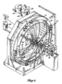
- FIGURE 1 illustrates an apparatus 10 made according to the present invention for producing a wrapped ski core.
- the apparatus includes a conventional braiding machine indicated generally at 12 for producing tubular braid.
- Such machines are commonly known as “maypole” braiders, and one source for such a machine is Mossberg Industries, Inc., 160 Bear Hill Road, Cumberland, Rhode Island 02864.
- the braiding machine includes a plurality of spools 14 positioned on a circular peripheral track 16.
- the spools carry strands of fiberglass and are adapted to move over and under each other as they travel around the periphery of the track 16.
- the strands of fiberglass 18 extending from the spools are directed through a guide ring 20 to a braiding nip area 22 where the movement of the spools causes the strands of yarn to be wrapped in opposing helixes to produce a braid about a ski core 24 passing longitudinally through guide 20.
- the strands of yarn initially pass over a larger outer guide ring 26, whose purpose, like that of guide ring 20, is to guide and direct the strands of fiberglass such that they are directed to the braiding nip at similar angles to allow braiding to easily occur.
- Haul-off apparatus 32 comprises a pair of endless belts 34 running around the pairs of rollers 36 and 38. Rollers 38 are rotatably driven. At least one pair of rollers 36 and 38 are also mounted on pneumatic cylinders or the like to allow the pairs of cylinders and overlying belts 34 to be moved toward each other to press against and grip the braid covered ski core to haul it through the braiding machine.
- a conventional cutting mechanism 40 is positioned outwardly of haul-off 32 to separate braid covered cores from each other.
- the location of the cut-off mechanism outward of the haul-off apparatus 32 and rollers 28 and 30 allow the braiding machine to braid on a continual basis by maintaining tension in the strands running from the bobbins on the braiding machine.
- the tension at which the strands are removed from the spools for braiding is about .25 pounds but may be any reaonably larger or smaller number so long as the machine braids effectively and the orientation of the strands on the core is maintained.
- the braiding machine 12 to braid angularly biased strands of fiberglass about ski core 24 produces a ski core covered in angularly biased braid, such as that shown in FIGURE 7.
- the fiberglass strands may be oriented at a variety of angles with respect to the longitudinal direction of the ski core with it being understood that maximum torsional stiffness occurs when the braid fibers are oriented at a 45 degree angle to the ski core.
- the thickness or thinness of the foamed plastic or wooden core over which the braid is laid grossly controls both the longitudinal and torsional flex of a ski at any point along its length.
- the ability to control the angle at which the braided fibers are placed on the ski by the apparatus of the present invention allows, for the first time, separate control of the longitudinal and torsional flex characteristics of a ski.
- the angle at which the knitted fibers are laid on the ski core with respect to the longitudinal dimension of the ski core is lowered, i.e., the braided strands move toward longitudinal alignment with the ski core and, thus, the longitudinal stiffness of the ski increases while the torsional rigidity is reduced.
- Such independent control of these two flex characteristics was not possible by simply making the ski core thinner or thicker.
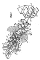
- Fiberglass strands 46 which are drawn from each of the spools 44, are directed over guide ring 48 through openings 51 in circular track 16 of the braiding machine 12 (FIGURE 2), over circular guide ring 26, through circular guide ring 20 and into the braiding nip area 22. It will be understood that the openings 51 on track 16 of the braiding machine do not move and, thus, strands 46 are not truly braided in braiding nip 22, but rather are merely intertwined with braided strands 18. Fiberglass strands 46, while intertwined with strands 18, maintain their longitudinal direction along the ski core 24 and, thus, add to the longitudinal stiffness of the completed ski.
- the longitudinal strands 46 are shown intertwined with the angularly biased braided strands 18.
- This three-strand fiberglass sock is tightly woven onto the ski core and conforms closely to its outer dimensions. It will be understood that the braided strands 18 of the three-strand braided sock of FIGURE 8 may still be varied in angular orientation by speeding or slowing the movement of the ski core through the braiding machine, or the speeding or slowing of the braiding machine itself.
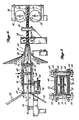
- Fiber guide 54 includes a strand receiving screen 56 comprising a metal plate having a plurality of holes 57 positioned above and below opening 58 through which ski core 24 passes. Holes 57 direct strands 52 toward springs 60 positioned above and below the ski core near the opposite end of fiber guide 54.
- springs 60 are end mounted in vertically oriented posts 66 and spiral about pins 62, which may be conventional bolts and nuts which are, in turn, mounted in openings 64 in posts 66.
- Fiberglass strands 52 are locked in springs 60 by removing pins 62 therefrom, pulling the fiberglass upwardly or downwardly through springs 60 and then reinserting locking pins 62. As shown in FIGURE 5, fiber strands 52 are then locked between springs 60 and pins 62.
- Strands 52 then extend through guide ring 20 and onto the top and bottom surfaces of the ski core in nip area 22 where they are covered and held by braided strands 18 and intertwined longitudinal strands 46.
- strands 52 may be formed of fiberglass similar to longitudinal strands 46, or may be fiberglass roving, or any other material having a characteristic useful in ski manufacture such as carbon, kevlar, polyester, metal wire or the like.
- vertical posts 66 are mounted on pivoting arms 68.
- the distal ends of arms 68 are mounted upon pivotal vertical shafts 70 which extend downwardly through fiber guide support plate 72.
- Meshing toothed gears 74 are fixedly mounted to the bottom of each shaft 70 such that the angular rotation of one shaft 70 caused by the inward or outward movement of the distal end of arms 68 as a ski core 24 moves therebetween is equally imparted to the other shaft 70 through gears 74.
- a conventional cylinder and piston arrangement 76 is mounted to the periphery of one of the toothed gears 74 to angularly bias the gear, interconnected arms 68 and posts 66 against the lateral side of ski core 24. In this way, as the width of the ski core narrows or widens as it passes between posts 66, arms 68 are continuously biased against the sides of the ski core and move inwardly and outwardly therewith.
- upper and lower guide rollers 78 are also mounted on the arms 68 of fiber guide 54 and at least the upper roller is biased downwardly against the top of ski core 24 by means of a conventional spring 80 mounted on the side of arm 68.
- strands of longitudinal material positioned on the top surface of ski core 24 and captured by angularly biased braid 18 are disclosed.
- FIGURE 10 longitudinally extending strands 52 extending beneath and captured by angularly biased strands 18 and intertwined longitudinally extending strands 46 are disclosed. It will be understood that any of the braided fiberglass covered ski core constructions shown in FIGURES 7-10 are considered to be novel products of the present invention. These fibers are braided and placed directly on a moving ski core in a continuous fashion to produce structures having improved characteristics not heretofore available in the art.
- varying the speed of movement of a ski core through the braiding machine, or varying the speed of the braiding machine as a ski core moves therethrough, will allow the impartation of differing flex patterns along the length of a single ski core. It is also contemplated that the speed of travel of the ski core or the speed of the braiding machine may be automatically controlled in a known manner to allow ski cores of a preselected flex pattern to be repeatedly and uniformly produced.
Abstract
Description
- The present invention relates to fiber reinforced skis in general and in particular to skis formed by the wet wrap or torsion box process wherein a wooden or foamed plastic core is wrapped in a fiber reinforced sheet impregnated with resin, "cooked" and cured under pressure in a mold with a base assembly. The invention comprises a unique braided fiber reinforced "sock" covering for a ski core which includes strands of reinforcement oriented at an angle to the longitudinal direction of the core and braided directly thereon. Longitudinally extending strands of reinforcement may be intertwined with the braided strands and other longitudinal strands of material may be positioned on the top or bottom surface of the ski core between the core and the braided reinforcement. The term "fiber reinforcement" is meant to include any high-modulus fibrous material such as glass, "Kevlar", carbon, metal wire, polypolyester, etc. suitable for the production of skis. A method and apparatus for manufacturing the fiber reinforced braided ski core is also disclosed.
- In the past, "wet wrap" or "torsion box" skis have typically been formed by impregnating a sheet of unidirectional fiberglass with epoxy resin. The core and any other internal components of the ski, such as fiberglass mat or a bias-ply precured fiberglass strip, are placed in the center of the unidirectional glass, again with resin applied. The unidirectional glass is then wrapped tightly around the core on all four sides. This unit is then placed in a mold, the base assembly set on top, and the mold closed. The unit is "cooked" under fairly high pressure for a period of time and, after the cure cycle, is removed from the mold. At this point, the ski is basically complete structurally and the rest of the production process is devoted to sanding, topping, finishing and other cosmetic operations. Ski cores have typically been wrapped or "laid up" by hand and this is a labor intensive and time-consuming process.
- It is known that unidirectional fiberglass is a material of great longitudinal tensile strength but little lateral strength. Thus, the torsional rigidity of skis was typically increased through the addition of randomly oriented fiberglass mat or angularly biased, precured fiberglass strips to the "sock" unit prior to wrapping. The longitudinally oriented unidirectional fiberglass imparted longitudinal rigidity to the ski. It is known that the orientation of fiberglass at a 45 degree angle to the longitudinal dimension of the ski core imparts the highest torsional rigidity to the ski. Of necessity, the use of a randomly oriented mat to increase torsional rigidity also resulted in unnecessarily increasing ski weight and expense since only a small percentage of the mat fibers were oriented at angles which enhanced torsional stiffness.
- The placement of 45 degree biased, precured fiberglass strips in the "sock" was an improvement in that it represented a more effective use of the strength characteristics of fiberglass in controlling torsional rigidity, but was undesirable in that it required additional lay-up and curing steps for the strips themselves. Further, the biased fiberglass was not wrapped around the core and thus did not obtain the benefits of strength and durability provided thereby.
- Another problem of the prior construction technique was that variations in lay-up from ski-to-ski created differences in torsional and longitudinal rigidity, thus making it difficult to produce a truly matched pair of skis. Further the known wrap process involves wrapping a rectangular sheet of fiberglass around the ski core which has a varying cross section along its length. This creates a large overlap of the sheet at the narrow waist of the ski and a small overlap at the wide tip. This adversely affects molded tolerances in the ski.
- The problems of hand lay-up have been attempted to be overcome in the past through the use of prebraided bias fiberglass socks which were slipped over a ski core prior to resin impregnation. Such socks were formed of multiple strands of fiberglass oriented at angles with respect to each other such that when the finished sock was slipped over the ski core, the strands were also oriented at angles, preferably 45 degree angles, to the ski core. Such prebraided fiberglass socks were difficult to use in that the braid tended to become loosened and unbraided while being slipped onto the ski core. In addition, the sock invariably fit loosely upon the ski core, thus creating difficulties in manufacture as well as quality control. The technique was also labor intensive and inflexible in design and still required premade contoured strips of longitudinal fiberglass.
- Prebraided fiberglass socks including longitudinally extending strands of fiberglass, as well as the angularly biased strands, were successful in overcoming the tendency of the solely angularly biased strand prebraided socks to become unbraided. Such three strand socks, however, had such little ability to expand that it was extremely difficult to slip them onto a ski core and the could not be effectively used in a production process.
- The present invention provides a unique ski core covering whereby strands of fiberglass are braided at preselected angles directly onto the core as the core is moved through a braiding machine. In addition, longitudinally directed strands of fiberglass may also be intertwined with the angularly biased strands during braiding. Other strands of longitudinally extending fiberglass or other desired materials may be positioned on the ski core while it is being passed through the braiding machine to allow for additional strengthing and tailoring of the flex characteristics of the ski.
- The present invention makes possible a lighter and yet stronger ski in that the use of randomly oriented fiberglass is eliminated and all strands which are used are either oriented longitudinally or at preselected angles such that the best use can be made of their tensile strength characteristics.
- The amount of fiberglass braided onto the ski core, as well as the angle of the braided fiberglass strands with respect to the ski core, can be varied by increasing or decreasing the speed of movement of the ski core through the braiding machine or the speed of the braiding machine itself. The equipment may be operated to allow the angle of the braided fiberglass strands with respect to the longitudinal dimension of the ski core to be varied along the ski core to separately control the torsional rigidity characteristics of the shovel or tail of a ski as desired. The braiding of the fiberglass onto the ski core under slight tension prevents unbraiding and holds the orientation of the fiberglass with respect to the ski after it is removed from the braiding machine and prior to its impregnation with epoxy and placement into a mold.
- A wrapped core for a fiberglass ski is formed by passing a foamed plastic, wood or other suitable type of ski core through a braiding machine whereby angularly biased strands of fiberglass are braided directly onto the ski core to cover it from one end to the other. Prior to braiding, other strands of fiberglass, or other suitable material, may be fed onto either or both the top and bottom surfaces of the ski core as it passes into the braiding machine, such that the longitudinal strands are captured and held by the overlying braid. The apparatus for feeding the longitudinal fibers onto the top and bottom surfaces of the ski core includes means for contouring the fibers to the varying widths of the ski. Longitudinal strands of fiberglass may also be intertwined directly into the braid to increase the longitudinal rigidity of the ski.
- Means are provided for varying either the speed of the braiding machine or the speed of travel of the ski core through the braiding machine to vary the angle at which the braided fibers are laid on the longitudinally extending ski core. This allows for easy control of the torsional stiffness characteristics of the ski and, thus, would allow different types of ski handling characteristics for different levels or styles of skiing to be manufactured on a single machine by simply varying the speed of movement of the ski core, the speed of the braiding machine, or modifying the amounts or types of longitudinal fibers or other materials which are laid upon the surfaces of the ski core prior to braiding.
- A unique, lightweight ski is provided which makes efficient use of the high tensile strength characteristics of fiberglass by orienting all strands of fiberglass longitudinally along preselected lines to produce a ski having a maximum strength-to-weight ratio. It provides a method and apparatus for producing uniform, lightweight skis having preselected torsional and longitudinal flex characteristics.
- The details of a typical embodiment of the present invention will be described in connection with the accompanying drawings in which:
- FIGURE 1 is a side elevation view of one embodiment of an apparatus for producing the wrapped core of the present invention;
- FIGURE 2 is a partial perspective view of the apparatus of FIGURE 1;
- FIGURE 3 is an enlarged partial perspective view of the braiding nip portion of the apparatus of the present invention;
- FIGURE 4 is a side elevation view of the braiding nip portion of the present invention;
- FIGURE 5 is a sectional view taken along lines 5-5 of FIGURE 4;
- FIGURE 6 is a top, plan view of the apparatus of FIGURE 4;
- FIGURE 7 is a plan view of a portion of a ski core showing angularly biased braid positioned thereon;
- FIGURE 8 is a top, plan view of a portion of a ski core showing angularly biased braid including longitudinally extending fibers intertwined therewith;
- FIGURE 9 is a plan view of a portion of a ski core showing angularly biased braid overlying longitudinally extending fibers positioned on the top surface of a ski core; and
- FIGURE 10 is a plan view of a portion of a ski core showing angularly biased braid including intertwined longitudinally extending fibers overlying longitudinally extending fibers positioned on the top surface of a ski core.
- FIGURE 1 illustrates an
apparatus 10 made according to the present invention for producing a wrapped ski core. The apparatus includes a conventional braiding machine indicated generally at 12 for producing tubular braid. Such machines are commonly known as "maypole" braiders, and one source for such a machine is Mossberg Industries, Inc., 160 Bear Hill Road, Cumberland, Rhode Island 02864. As is best seen in FIGURE 2, the braiding machine includes a plurality ofspools 14 positioned on a circular peripheral track 16. The spools carry strands of fiberglass and are adapted to move over and under each other as they travel around the periphery of the track 16. The strands offiberglass 18 extending from the spools are directed through aguide ring 20 to abraiding nip area 22 where the movement of the spools causes the strands of yarn to be wrapped in opposing helixes to produce a braid about aski core 24 passing longitudinally throughguide 20. - As illustrated, the strands of yarn initially pass over a larger
outer guide ring 26, whose purpose, like that ofguide ring 20, is to guide and direct the strands of fiberglass such that they are directed to the braiding nip at similar angles to allow braiding to easily occur. - Referring again to FIGURE 1, it will be seen that horizontal and
vertical guide rollers apparatus 32. Haul-offapparatus 32 comprises a pair ofendless belts 34 running around the pairs ofrollers Rollers 38 are rotatably driven. At least one pair ofrollers overlying belts 34 to be moved toward each other to press against and grip the braid covered ski core to haul it through the braiding machine. Aconventional cutting mechanism 40 is positioned outwardly of haul-off 32 to separate braid covered cores from each other. The location of the cut-off mechanism outward of the haul-off apparatus 32 androllers - Operation of the
braiding machine 12 to braid angularly biased strands of fiberglass aboutski core 24 produces a ski core covered in angularly biased braid, such as that shown in FIGURE 7. The fiberglass strands may be oriented at a variety of angles with respect to the longitudinal direction of the ski core with it being understood that maximum torsional stiffness occurs when the braid fibers are oriented at a 45 degree angle to the ski core. - It will be understood that the thickness or thinness of the foamed plastic or wooden core over which the braid is laid grossly controls both the longitudinal and torsional flex of a ski at any point along its length. The thinner a ski core at any point, the less stiff it is. The ability to control the angle at which the braided fibers are placed on the ski by the apparatus of the present invention allows, for the first time, separate control of the longitudinal and torsional flex characteristics of a ski. For example, as the speed of movement of a ski core through the
braiding machine 12 is increased, the angle at which the knitted fibers are laid on the ski core with respect to the longitudinal dimension of the ski core is lowered, i.e., the braided strands move toward longitudinal alignment with the ski core and, thus, the longitudinal stiffness of the ski increases while the torsional rigidity is reduced. Such independent control of these two flex characteristics was not possible by simply making the ski core thinner or thicker. - Referring again to FIGURE 1, it will be seen that
rack 42 holding a plurality ofspools 44 of fiberglass roving is also disclosed.Fiberglass strands 46, which are drawn from each of thespools 44, are directed overguide ring 48 throughopenings 51 in circular track 16 of the braiding machine 12 (FIGURE 2), overcircular guide ring 26, throughcircular guide ring 20 and into the braiding niparea 22. It will be understood that theopenings 51 on track 16 of the braiding machine do not move and, thus,strands 46 are not truly braided in braiding nip 22, but rather are merely intertwined with braidedstrands 18.Fiberglass strands 46, while intertwined withstrands 18, maintain their longitudinal direction along theski core 24 and, thus, add to the longitudinal stiffness of the completed ski. - Referring to FIGURE 8, the
longitudinal strands 46 are shown intertwined with the angularly biased braidedstrands 18. This three-strand fiberglass sock is tightly woven onto the ski core and conforms closely to its outer dimensions. It will be understood that the braidedstrands 18 of the three-strand braided sock of FIGURE 8 may still be varied in angular orientation by speeding or slowing the movement of the ski core through the braiding machine, or the speeding or slowing of the braiding machine itself. - Referring again to FIGURE 1, it will be noted that
racks 42 holdother spools 50 of fiberglass material, thestrands 52 of which are led tofiber guide 54 which is best shown in FIGURES 3 and 4.Fiber guide 54 includes astrand receiving screen 56 comprising a metal plate having a plurality ofholes 57 positioned above and below opening 58 through whichski core 24 passes.Holes 57direct strands 52 towardsprings 60 positioned above and below the ski core near the opposite end offiber guide 54. As best shown in FIGURE 5, springs 60 are end mounted in vertically orientedposts 66 and spiral aboutpins 62, which may be conventional bolts and nuts which are, in turn, mounted inopenings 64 inposts 66. -
Fiberglass strands 52 are locked insprings 60 by removingpins 62 therefrom, pulling the fiberglass upwardly or downwardly throughsprings 60 and then reinserting locking pins 62. As shown in FIGURE 5,fiber strands 52 are then locked betweensprings 60 and pins 62. -
Strands 52 then extend throughguide ring 20 and onto the top and bottom surfaces of the ski core innip area 22 where they are covered and held by braidedstrands 18 and intertwinedlongitudinal strands 46. - It will be understood that
strands 52 may be formed of fiberglass similar tolongitudinal strands 46, or may be fiberglass roving, or any other material having a characteristic useful in ski manufacture such as carbon, kevlar, polyester, metal wire or the like. - It will also be understood that unequal amounts of fiber material may be deposited on the top or bottom surface of the ski core as desired by varying the number of spools of material feeding fiber strands to the upper or lower guide holes 57 of
plate 56. While only a pair of spools have been shown feeding strands of material to the fiber guide in FIGURE 1, it will be understood that many more spools will actually be used during ski production. - Referring additionally to FIGURE 6, it will be seen that
vertical posts 66 are mounted on pivotingarms 68. The distal ends ofarms 68 are mounted upon pivotalvertical shafts 70 which extend downwardly through fiberguide support plate 72. Meshing toothed gears 74 are fixedly mounted to the bottom of eachshaft 70 such that the angular rotation of oneshaft 70 caused by the inward or outward movement of the distal end ofarms 68 as aski core 24 moves therebetween is equally imparted to theother shaft 70 throughgears 74. - A conventional cylinder and
piston arrangement 76 is mounted to the periphery of one of the toothed gears 74 to angularly bias the gear,interconnected arms 68 andposts 66 against the lateral side ofski core 24. In this way, as the width of the ski core narrows or widens as it passes betweenposts 66,arms 68 are continuously biased against the sides of the ski core and move inwardly and outwardly therewith. - Since, as best shown in FIGURE 5, the ends of
springs 60 are fixedly mounted inposts 66, the lateral movement ofposts 66 as a ski core of varying width passes therebetween causes springs 60 to flex inwardly and outwardly. Sincefiberglass strands 52 are captured beneath the turns ofsprings 60, the strands are also moved inwardly and outwardly assprings 60 flex and, in this way,fiberglass strands 52 are variably spaced or contoured with respect to the upper and lower surfaces ofski core 24 on which they are deposited as the width of the ski core varies. - As is best shown in FIGURE 4, upper and
lower guide rollers 78 are also mounted on thearms 68 offiber guide 54 and at least the upper roller is biased downwardly against the top ofski core 24 by means of aconventional spring 80 mounted on the side ofarm 68. - Referring to FIGURE 9, strands of longitudinal material positioned on the top surface of
ski core 24 and captured by angularly biasedbraid 18 are disclosed. - Referring to FIGURE 10, longitudinally extending
strands 52 extending beneath and captured by angularly biasedstrands 18 and intertwined longitudinally extendingstrands 46 are disclosed. It will be understood that any of the braided fiberglass covered ski core constructions shown in FIGURES 7-10 are considered to be novel products of the present invention. These fibers are braided and placed directly on a moving ski core in a continuous fashion to produce structures having improved characteristics not heretofore available in the art. - The above-described apparatus and the method of manufacturing these and other unique braided ski cores are also considered to be novel features of this invention.
- It is contemplated that varying the speed of movement of a ski core through the braiding machine, or varying the speed of the braiding machine as a ski core moves therethrough, will allow the impartation of differing flex patterns along the length of a single ski core. It is also contemplated that the speed of travel of the ski core or the speed of the braiding machine may be automatically controlled in a known manner to allow ski cores of a preselected flex pattern to be repeatedly and uniformly produced.
- As will be apparent to those skilled in the art to which the invention is addressed, the present invention may be embodied in forms other than those specifically disclosed above without departing from the spirit or essential characteristics of the invention. The particular embodiment of the apparatus, method and product described above is therefore to be considered in all respects as being merely illustrative of one form of apparatus, method and product capable of carrying out the present invention.
- The scope of the invention is as set forth in the appended claims, rather than in the foregoing description.
Claims (26)
a longitudinal core (24) and characterised in that it further comprises a first set of continuous strands of fiber (18) braided directly thereon, said first set of strands (18) being helically wrapped about said core (24) and biased at angles with respect to the longitudinal dimension of said core (24).
a second set of longitudinally extending strands of fiber (46) interwoven with said first set of strands (18).
moving a core for a ski longitudinally along a path through a braiding machine (12);
braiding a first set of continuous stands of reinforcing fiber (18) about the core (24) as the core is moved longitudinally along its path; in such a manner that the first set of strands (18) are angularly orientated with respect to the length of the core; and,
maintaining tension on the first set of strands (18) during braiding.
means for moving a core (24) for a ski longitudinally along a path through a braiding machine (12); and,
means for braiding a first set of continuous strands of reinforcing fiber (18) about the core (24) at biaxial directions to the length of the core as the core (24) is moved longitudinally along its path.
Priority Applications (1)
| Application Number | Priority Date | Filing Date | Title |
|---|---|---|---|
| AT87304823T ATE65189T1 (en) | 1986-06-06 | 1987-06-01 | FIBER-REINFORCED BRAIDED CORE OF A SKI AND METHOD AND DEVICE FOR ITS MANUFACTURE. |
Applications Claiming Priority (2)
| Application Number | Priority Date | Filing Date | Title |
|---|---|---|---|
| US871443 | 1986-06-06 | ||
| US06/871,443 US4690850A (en) | 1986-06-06 | 1986-06-06 | Fiber reinforced braided ski core and method and apparatus for making same |
Publications (3)
| Publication Number | Publication Date |
|---|---|
| EP0249372A2 true EP0249372A2 (en) | 1987-12-16 |
| EP0249372A3 EP0249372A3 (en) | 1989-02-08 |
| EP0249372B1 EP0249372B1 (en) | 1991-07-17 |
Family
ID=25357444
Family Applications (1)
| Application Number | Title | Priority Date | Filing Date |
|---|---|---|---|
| EP87304823A Expired - Lifetime EP0249372B1 (en) | 1986-06-06 | 1987-06-01 | Fiber reinforced braided ski core and method and apparatus for making same |
Country Status (11)
| Country | Link |
|---|---|
| US (1) | US4690850A (en) |
| EP (1) | EP0249372B1 (en) |
| JP (1) | JPS62292181A (en) |
| KR (1) | KR940003244B1 (en) |
| AT (1) | ATE65189T1 (en) |
| CA (1) | CA1291494C (en) |
| DE (1) | DE3771394D1 (en) |
| DK (1) | DK167654B1 (en) |
| ES (1) | ES2023414B3 (en) |
| FI (1) | FI88874C (en) |
| NO (1) | NO165663C (en) |
Cited By (6)
| Publication number | Priority date | Publication date | Assignee | Title |
|---|---|---|---|---|
| WO1997000103A2 (en) * | 1995-06-16 | 1997-01-03 | Kästle Aktiengesellschaft | Ski |
| WO2007090556A2 (en) | 2006-02-03 | 2007-08-16 | Sgl Kümpers Gmbh & Co. Kg | Energy-absorbing textile structure, in particular for use in vehicle construction and method for producing said structure |
| US8114793B2 (en) * | 2006-02-11 | 2012-02-14 | Sgl Kumpers Gmbh & Co. Kg | Three-dimensional textile component structure consisting of high-tensile threads and method for producing said structure |
| DE102012205906A1 (en) * | 2012-04-11 | 2013-10-17 | Leichtbau-Zentrum Sachsen Gmbh | Method for manufacturing dynamic braid pattern for fiber reinforcement element of fiber composite component, involves changing number of nodes with fiber strands or number of fiber strands with constant number of nodes in various regions |
| WO2019210324A1 (en) * | 2018-04-27 | 2019-10-31 | K2 Sports, Llc | Ski with composite structure having arcuate fibers |
| EP3705161A1 (en) * | 2019-03-08 | 2020-09-09 | Völkl Sports GmbH | Glide board with composite reinforced by fibre |
Families Citing this family (30)
| Publication number | Priority date | Publication date | Assignee | Title |
|---|---|---|---|---|
| NO870539L (en) * | 1986-02-21 | 1987-08-24 | Rohrmoser Alois Skifabrik | REINFORCEMENT ELEMENT FOR INCORPORATION IN A RESIN AND USE OF THIS ELEMENT. |
| FR2641444B1 (en) * | 1989-01-09 | 1991-02-22 | Notex Sa | STABILIZING TABLECLOTH WITH HEATING INSERT FOR ABOVE GROUND CULTURE AND FOR PROTECTED CONTAINER PLATFORM |
| US5769445A (en) * | 1994-04-01 | 1998-06-23 | Morrow Snowboards, Inc. | Snowboard |
| JP2765511B2 (en) * | 1995-04-04 | 1998-06-18 | 村田機械株式会社 | Pipe manufacturing equipment |
| FR2749519B1 (en) * | 1996-06-06 | 1998-09-11 | Salomon Sa | GLIDING BOARD COVERING COMPLEX |
| JP2598907Y2 (en) * | 1996-08-01 | 1999-08-23 | 村田機械株式会社 | Braider |
| US5789078A (en) * | 1996-09-13 | 1998-08-04 | Owens-Corning Fiberglas Technology, Inc. | Reinforcement mat |
| DE19758648C2 (en) * | 1997-06-20 | 2002-05-23 | Guido Langenbach | Crash protection device for high-speed roll-up doors and high-speed roll-up door |
| US6105991A (en) * | 1997-11-20 | 2000-08-22 | The Burton Corporation | Core for a gliding board |
| JP2000014843A (en) * | 1998-04-27 | 2000-01-18 | Fujikura Rubber Ltd | Golf club shaft |
| US6311377B1 (en) | 1998-04-28 | 2001-11-06 | Owens Corning Fiberglass Technology, Inc. | Apparatus and method for spreading fibrous tows into linear arrays of generally uniform density and products made thereby |
| US6502850B1 (en) | 1999-10-12 | 2003-01-07 | The Burton Corporation | Core for a gliding board |
| DK1265744T3 (en) * | 1999-12-28 | 2016-03-29 | Milliken & Co | Fibre reinforced composite cores |
| FR2833849B1 (en) * | 2001-12-21 | 2004-03-12 | Salomon Sa | REINFORCEMENT SHEET OF A COMPOSITE STRUCTURE SUCH AS A WORKING OR SLIDING BOARD |
| US20050055933A1 (en) * | 2003-09-03 | 2005-03-17 | Dow Richard M. | Woven metallic reinforcement and method of fabricating same |
| US7563497B2 (en) * | 2004-12-27 | 2009-07-21 | Mkp Structural Design Associates, Inc. | Lightweight, rigid composite structures |
| EP1693089B1 (en) * | 2005-02-16 | 2009-01-07 | Skis Rossignol | Slide board |
| US7588420B2 (en) * | 2005-06-02 | 2009-09-15 | Air Cool Industrial Co., Ltd. | Customized fan blade and method of making same |
| US7694621B1 (en) | 2005-07-22 | 2010-04-13 | Mkp Structural Design Associates, Inc. | Lightweight composite armor |
| US7490539B2 (en) | 2005-07-22 | 2009-02-17 | Mkp Structural Design Associates, Inc. | Lightweight composite armor |
| ATE519879T1 (en) * | 2007-09-14 | 2011-08-15 | Wesp Holding B V | DEVICE AND METHOD FOR BRAIDING FIBERS INTO A BRAID STRUCTURE |
| DE102008014380B4 (en) * | 2008-03-17 | 2011-06-30 | EADS Deutschland GmbH, 85521 | Apparatus and method for winding a fiber material on a winding core in the manufacture of a fiber composite component |
| US8652629B2 (en) * | 2010-08-31 | 2014-02-18 | Frp Transmission Innovations Inc. | Transmission cross arm |
| DE102011009641B4 (en) * | 2011-01-27 | 2013-04-04 | Puma SE | Method for producing a shoe upper of a shoe, in particular a sports shoe |
| DE102012222762A1 (en) * | 2012-12-11 | 2014-06-12 | Sgl Kümpers Gmbh & Co. Kg | Braiding machine for manufacturing braided fabric structures, has ring-shaped structure arranged in section between discharge eyelets of bobbins and braiding ring, where outer diameter of structure is larger than inner diameter of ring |
| US11447901B2 (en) | 2013-04-12 | 2022-09-20 | EverestMedica LLC | Method of making a surgical braid |
| US9610077B2 (en) * | 2013-08-08 | 2017-04-04 | EverestMedica LLC | Round-flat-round surgical braids |
| DE102014212063A1 (en) * | 2014-06-24 | 2015-12-24 | Universität Stuttgart | Pressing device for pressing a braided hose to a component core and braiding machine |
| CN108950855A (en) * | 2017-05-19 | 2018-12-07 | 刘念 | Closed ring tubing braider and its weaving method |
| CN115976713B (en) * | 2023-03-22 | 2023-12-29 | 广东宝维新材料科技有限公司 | Warp let-off tension adjusting device based on carbon fiber loom |
Citations (3)
| Publication number | Priority date | Publication date | Assignee | Title |
|---|---|---|---|---|
| FR1493179A (en) * | 1965-11-16 | 1967-08-25 | Golf club handle and method of manufacturing the same | |
| AT293239B (en) * | 1967-03-30 | 1971-09-27 | Amf Inc | Ski with a prefabricated core consisting essentially of plastic material and method for its manufacture |
| US3998458A (en) * | 1974-07-12 | 1976-12-21 | Hitachi Chemical Company, Ltd. | Golf club shaft |
Family Cites Families (23)
| Publication number | Priority date | Publication date | Assignee | Title |
|---|---|---|---|---|
| US273847A (en) * | 1883-03-13 | George hunzingbr | ||
| US1820934A (en) * | 1928-06-15 | 1931-09-01 | Henry W Buhler | Molded trimming |
| US3322435A (en) * | 1965-01-29 | 1967-05-30 | Kirschner Howard William | Ski |
| US3393918A (en) * | 1965-04-05 | 1968-07-23 | Styka Andrew | Filament wound resin reinforced structure and method |
| US3276784A (en) * | 1965-05-12 | 1966-10-04 | Jr Henry M Anderson | Laminated ski having a foam filled honeycomb core |
| US3490983A (en) * | 1965-05-17 | 1970-01-20 | Hitco | Fiber reinforced structures and methods of making the same |
| US3874972A (en) * | 1967-07-05 | 1975-04-01 | Mancar Trust | Process for the manufacture of improved reinforced glass pipes and other articles |
| US3740301A (en) * | 1971-07-14 | 1973-06-19 | Tensor Corp | Elongated lightweight structure |
| US3893681A (en) * | 1971-07-14 | 1975-07-08 | Tensor Corp | Ski |
| US3902732A (en) * | 1973-02-14 | 1975-09-02 | Jr Albert A Fosha | Advanced composition ski |
| US3844576A (en) * | 1973-07-18 | 1974-10-29 | Olin Corp | Vibration damped ski |
| US4035000A (en) * | 1974-04-09 | 1977-07-12 | Daniel Lacroix | Skis |
| JPS51135725A (en) * | 1975-05-20 | 1976-11-24 | Sokichiro Yamabe | Method of manufacturing core members for wooden ski bodies |
| US4063838A (en) * | 1976-05-07 | 1977-12-20 | Fiber Glass Systems, Inc. | Rod construction and method of forming the same |
| US4283446A (en) * | 1976-09-07 | 1981-08-11 | Shakespeare Company | Fiber reinforced plastic members |
| US4094528A (en) * | 1976-10-21 | 1978-06-13 | John Michael Cluzel | Ski structure |
| US4264278A (en) * | 1977-10-31 | 1981-04-28 | Oscar Weingart | Blade or spar |
| US4197348A (en) * | 1978-02-15 | 1980-04-08 | Magna-Ply Company | Wrapped elongated structure in which positioning of a one sided adhesive tape is such as to permit wrapping to move relative to a core |
| JPS5648189A (en) * | 1979-09-27 | 1981-05-01 | Toshiba Corp | Method of forming photothyristor circuit |
| JPS5714863A (en) * | 1980-06-30 | 1982-01-26 | Fujitsu Ltd | Method for replenishing developing powder of electrostatic printer |
| US4529139A (en) * | 1980-10-20 | 1985-07-16 | United Technologies Corporation | Method of manufacturing a filament wound article |
| US4381960A (en) * | 1981-12-28 | 1983-05-03 | United Technologies Corporation | Method of manufacturing a filament wound article |
| US4519290A (en) * | 1983-11-16 | 1985-05-28 | Thiokol Corporation | Braided preform for refractory articles and method of making |
-
1986
- 1986-06-06 US US06/871,443 patent/US4690850A/en not_active Expired - Lifetime
-
1987
- 1987-03-05 CA CA000531201A patent/CA1291494C/en not_active Expired - Lifetime
- 1987-03-17 DK DK137387A patent/DK167654B1/en not_active IP Right Cessation
- 1987-03-18 NO NO871124A patent/NO165663C/en unknown
- 1987-03-30 KR KR1019870002946A patent/KR940003244B1/en not_active IP Right Cessation
- 1987-03-31 JP JP62079544A patent/JPS62292181A/en active Granted
- 1987-04-06 FI FI871486A patent/FI88874C/en not_active IP Right Cessation
- 1987-06-01 AT AT87304823T patent/ATE65189T1/en active
- 1987-06-01 ES ES87304823T patent/ES2023414B3/en not_active Expired - Lifetime
- 1987-06-01 EP EP87304823A patent/EP0249372B1/en not_active Expired - Lifetime
- 1987-06-01 DE DE8787304823T patent/DE3771394D1/en not_active Expired - Lifetime
Patent Citations (3)
| Publication number | Priority date | Publication date | Assignee | Title |
|---|---|---|---|---|
| FR1493179A (en) * | 1965-11-16 | 1967-08-25 | Golf club handle and method of manufacturing the same | |
| AT293239B (en) * | 1967-03-30 | 1971-09-27 | Amf Inc | Ski with a prefabricated core consisting essentially of plastic material and method for its manufacture |
| US3998458A (en) * | 1974-07-12 | 1976-12-21 | Hitachi Chemical Company, Ltd. | Golf club shaft |
Non-Patent Citations (2)
| Title |
|---|
| PATENT ABSTRACTS OF JAPAN * |
| PATENT ABSTRACTS OF JAPAN, volume 1, no. 23, page 1704 M 76, 25th March 1977 * |
Cited By (13)
| Publication number | Priority date | Publication date | Assignee | Title |
|---|---|---|---|---|
| WO1997000103A3 (en) * | 1995-06-16 | 1997-02-27 | Kaestle Ag | Ski |
| WO1997000103A2 (en) * | 1995-06-16 | 1997-01-03 | Kästle Aktiengesellschaft | Ski |
| CN101379235B (en) * | 2006-02-03 | 2015-04-01 | Sgl金佩尔斯有限及两合公司 | Energy-absorbing textile structure, in particular for use in vehicle construction and method for producing said structure |
| WO2007090556A2 (en) | 2006-02-03 | 2007-08-16 | Sgl Kümpers Gmbh & Co. Kg | Energy-absorbing textile structure, in particular for use in vehicle construction and method for producing said structure |
| WO2007090556A3 (en) * | 2006-02-03 | 2007-10-11 | Kuempers Gmbh & Co Kg | Energy-absorbing textile structure, in particular for use in vehicle construction and method for producing said structure |
| CN101379235A (en) * | 2006-02-03 | 2009-03-04 | Sgl金佩尔斯有限及两合公司 | Energy-absorbing textile structure, in particular for use in vehicle construction and method for producing said structure |
| US8877661B2 (en) | 2006-02-03 | 2014-11-04 | Sgl Kümpers Gmbh & Co. Kg | Energy-absorbing textile structure, in particular for use in vehicle construction and method for producing said structure |
| US8114793B2 (en) * | 2006-02-11 | 2012-02-14 | Sgl Kumpers Gmbh & Co. Kg | Three-dimensional textile component structure consisting of high-tensile threads and method for producing said structure |
| DE102012205906A1 (en) * | 2012-04-11 | 2013-10-17 | Leichtbau-Zentrum Sachsen Gmbh | Method for manufacturing dynamic braid pattern for fiber reinforcement element of fiber composite component, involves changing number of nodes with fiber strands or number of fiber strands with constant number of nodes in various regions |
| WO2019210324A1 (en) * | 2018-04-27 | 2019-10-31 | K2 Sports, Llc | Ski with composite structure having arcuate fibers |
| US10857445B2 (en) | 2018-04-27 | 2020-12-08 | K2 Sports, Llc | Ski with composite structure having arcuate fibers |
| EP3705161A1 (en) * | 2019-03-08 | 2020-09-09 | Völkl Sports GmbH | Glide board with composite reinforced by fibre |
| US11452931B2 (en) * | 2019-03-08 | 2022-09-27 | Völkl Sports Gmbh | Sliding board with fiber composite material |
Also Published As
| Publication number | Publication date |
|---|---|
| KR880000119A (en) | 1988-03-23 |
| FI88874C (en) | 1993-07-26 |
| NO165663B (en) | 1990-12-10 |
| NO871124L (en) | 1987-12-07 |
| ES2023414B3 (en) | 1992-01-16 |
| JPH0374594B2 (en) | 1991-11-27 |
| NO871124D0 (en) | 1987-03-18 |
| DK137387D0 (en) | 1987-03-17 |
| KR940003244B1 (en) | 1994-04-16 |
| FI871486A (en) | 1987-12-07 |
| EP0249372B1 (en) | 1991-07-17 |
| CA1291494C (en) | 1991-10-29 |
| JPS62292181A (en) | 1987-12-18 |
| ATE65189T1 (en) | 1991-08-15 |
| FI871486A0 (en) | 1987-04-06 |
| EP0249372A3 (en) | 1989-02-08 |
| DK137387A (en) | 1987-12-07 |
| DE3771394D1 (en) | 1991-08-22 |
| NO165663C (en) | 1991-03-20 |
| DK167654B1 (en) | 1993-12-06 |
| US4690850A (en) | 1987-09-01 |
| FI88874B (en) | 1993-04-15 |
Similar Documents
| Publication | Publication Date | Title |
|---|---|---|
| US4690850A (en) | Fiber reinforced braided ski core and method and apparatus for making same | |
| US4857124A (en) | Fiber-reinforced plastic strut connecting link | |
| US5503928A (en) | Fibre reinforced composites | |
| US4992313A (en) | Fiber-reinforced plastic strut connecting link | |
| CA2626545C (en) | Fabricating three-dimensional annular fiber structures | |
| CA1234284A (en) | Method and apparatus for production of bias fabrics | |
| US3044146A (en) | Composite fibrous glass bodies | |
| JP3727656B2 (en) | Press belt and method for manufacturing the press belt | |
| JPH10510012A (en) | Improved braided preforms for composites | |
| US3909893A (en) | Process for making tubular needlefelted material | |
| JP2011516301A (en) | Method for producing fiber composite material or fiber reinforced plastic part from roving by mold, and mold for carrying out the method | |
| CA1130713A (en) | High strength composite of resin, helically wound fibers and swirled continuous fibers and method of its formation | |
| DE60005597T2 (en) | Belt for a shoe press and process for its manufacture | |
| CA1121705A (en) | High strength composite of resin, helically wound fibers and chopped fibers and method of its formation | |
| EP2217751B1 (en) | A method of manufacturing a fibrous structure and an apparatus therefor | |
| GB2102381A (en) | Winding filament bands | |
| JPH06278216A (en) | Production of tubular member such as golf shaft of fishing rod | |
| JPS6153459B2 (en) | ||
| DE102008052671B3 (en) | Braiding device for braiding curve-shaped braided core utilized for forming frame of airplane, has braiding devices that are rotatable around rotational axis and/or movable transverse to conveying direction | |
| JPH07507106A (en) | Multi-axis nonwoven fabric manufacturing equipment | |
| EP0303685A4 (en) | Method for multiple-end-close-set uniform density parallel weft insertion and products thereof. | |
| CA1158034A (en) | Unspun yarn | |
| JPH0749351B2 (en) | Method for making a fiber composite laminate composed of fiber composite material | |
| JPH04108145A (en) | Production of fiber-reinforced plastics | |
| EP0414212A1 (en) | Method of manufacturing a loom shuttle to a loom and the loom shuttle made by the method |
Legal Events
| Date | Code | Title | Description |
|---|---|---|---|
| PUAI | Public reference made under article 153(3) epc to a published international application that has entered the european phase |
Free format text: ORIGINAL CODE: 0009012 |
|
| AK | Designated contracting states |
Kind code of ref document: A2 Designated state(s): AT BE CH DE ES FR GB IT LI LU NL SE |
|
| PUAL | Search report despatched |
Free format text: ORIGINAL CODE: 0009013 |
|
| AK | Designated contracting states |
Kind code of ref document: A3 Designated state(s): AT BE CH DE ES FR GB IT LI LU NL SE |
|
| RHK1 | Main classification (correction) |
Ipc: A63C 5/12 |
|
| 17P | Request for examination filed |
Effective date: 19890803 |
|
| 17Q | First examination report despatched |
Effective date: 19900118 |
|
| ITF | It: translation for a ep patent filed |
Owner name: BARZANO' E ZANARDO ROMA S.P.A. |
|
| GRAA | (expected) grant |
Free format text: ORIGINAL CODE: 0009210 |
|
| AK | Designated contracting states |
Kind code of ref document: B1 Designated state(s): AT BE CH DE ES FR GB IT LI LU NL SE |
|
| PG25 | Lapsed in a contracting state [announced via postgrant information from national office to epo] |
Ref country code: NL Effective date: 19910717 Ref country code: BE Effective date: 19910717 |
|
| REF | Corresponds to: |
Ref document number: 65189 Country of ref document: AT Date of ref document: 19910815 Kind code of ref document: T |
|
| REF | Corresponds to: |
Ref document number: 3771394 Country of ref document: DE Date of ref document: 19910822 |
|
| ET | Fr: translation filed | ||
| NLV1 | Nl: lapsed or annulled due to failure to fulfill the requirements of art. 29p and 29m of the patents act | ||
| REG | Reference to a national code |
Ref country code: ES Ref legal event code: FG2A Ref document number: 2023414 Country of ref document: ES Kind code of ref document: B3 |
|
| PLBE | No opposition filed within time limit |
Free format text: ORIGINAL CODE: 0009261 |
|
| STAA | Information on the status of an ep patent application or granted ep patent |
Free format text: STATUS: NO OPPOSITION FILED WITHIN TIME LIMIT |
|
| PG25 | Lapsed in a contracting state [announced via postgrant information from national office to epo] |
Ref country code: LU Free format text: LAPSE BECAUSE OF NON-PAYMENT OF DUE FEES Effective date: 19920630 |
|
| 26N | No opposition filed | ||
| EAL | Se: european patent in force in sweden |
Ref document number: 87304823.5 |
|
| PGFP | Annual fee paid to national office [announced via postgrant information from national office to epo] |
Ref country code: ES Payment date: 19950615 Year of fee payment: 9 |
|
| PG25 | Lapsed in a contracting state [announced via postgrant information from national office to epo] |
Ref country code: ES Free format text: LAPSE BECAUSE OF THE APPLICANT RENOUNCES Effective date: 19960603 |
|
| PGFP | Annual fee paid to national office [announced via postgrant information from national office to epo] |
Ref country code: GB Payment date: 19970425 Year of fee payment: 11 |
|
| PGFP | Annual fee paid to national office [announced via postgrant information from national office to epo] |
Ref country code: SE Payment date: 19970523 Year of fee payment: 11 |
|
| PGFP | Annual fee paid to national office [announced via postgrant information from national office to epo] |
Ref country code: AT Payment date: 19970528 Year of fee payment: 11 |
|
| PG25 | Lapsed in a contracting state [announced via postgrant information from national office to epo] |
Ref country code: GB Free format text: LAPSE BECAUSE OF NON-PAYMENT OF DUE FEES Effective date: 19980601 Ref country code: AT Free format text: LAPSE BECAUSE OF NON-PAYMENT OF DUE FEES Effective date: 19980601 |
|
| PG25 | Lapsed in a contracting state [announced via postgrant information from national office to epo] |
Ref country code: SE Free format text: LAPSE BECAUSE OF NON-PAYMENT OF DUE FEES Effective date: 19980602 |
|
| GBPC | Gb: european patent ceased through non-payment of renewal fee |
Effective date: 19980601 |
|
| EUG | Se: european patent has lapsed |
Ref document number: 87304823.5 |
|
| REG | Reference to a national code |
Ref country code: ES Ref legal event code: FD2A Effective date: 19991007 |
|
| PGFP | Annual fee paid to national office [announced via postgrant information from national office to epo] |
Ref country code: FR Payment date: 20060620 Year of fee payment: 20 |
|
| PGFP | Annual fee paid to national office [announced via postgrant information from national office to epo] |
Ref country code: CH Payment date: 20060628 Year of fee payment: 20 |
|
| PGFP | Annual fee paid to national office [announced via postgrant information from national office to epo] |
Ref country code: IT Payment date: 20060630 Year of fee payment: 20 |
|
| PGFP | Annual fee paid to national office [announced via postgrant information from national office to epo] |
Ref country code: DE Payment date: 20060731 Year of fee payment: 20 |
|
| REG | Reference to a national code |
Ref country code: CH Ref legal event code: PL |