DE102012205906A1 - Method for manufacturing dynamic braid pattern for fiber reinforcement element of fiber composite component, involves changing number of nodes with fiber strands or number of fiber strands with constant number of nodes in various regions - Google Patents
Method for manufacturing dynamic braid pattern for fiber reinforcement element of fiber composite component, involves changing number of nodes with fiber strands or number of fiber strands with constant number of nodes in various regions Download PDFInfo
- Publication number
- DE102012205906A1 DE102012205906A1 DE201210205906 DE102012205906A DE102012205906A1 DE 102012205906 A1 DE102012205906 A1 DE 102012205906A1 DE 201210205906 DE201210205906 DE 201210205906 DE 102012205906 A DE102012205906 A DE 102012205906A DE 102012205906 A1 DE102012205906 A1 DE 102012205906A1
- Authority
- DE
- Germany
- Prior art keywords
- fiber
- fiber strands
- nodes
- braiding
- fibers
- Prior art date
- Legal status (The legal status is an assumption and is not a legal conclusion. Google has not performed a legal analysis and makes no representation as to the accuracy of the status listed.)
- Withdrawn
Links
Images


Classifications
-
- D—TEXTILES; PAPER
- D04—BRAIDING; LACE-MAKING; KNITTING; TRIMMINGS; NON-WOVEN FABRICS
- D04C—BRAIDING OR MANUFACTURE OF LACE, INCLUDING BOBBIN-NET OR CARBONISED LACE; BRAIDING MACHINES; BRAID; LACE
- D04C3/00—Braiding or lacing machines
- D04C3/40—Braiding or lacing machines for making tubular braids by circulating strand supplies around braiding centre at equal distances
-
- B—PERFORMING OPERATIONS; TRANSPORTING
- B29—WORKING OF PLASTICS; WORKING OF SUBSTANCES IN A PLASTIC STATE IN GENERAL
- B29C—SHAPING OR JOINING OF PLASTICS; SHAPING OF MATERIAL IN A PLASTIC STATE, NOT OTHERWISE PROVIDED FOR; AFTER-TREATMENT OF THE SHAPED PRODUCTS, e.g. REPAIRING
- B29C70/00—Shaping composites, i.e. plastics material comprising reinforcements, fillers or preformed parts, e.g. inserts
- B29C70/04—Shaping composites, i.e. plastics material comprising reinforcements, fillers or preformed parts, e.g. inserts comprising reinforcements only, e.g. self-reinforcing plastics
- B29C70/06—Fibrous reinforcements only
- B29C70/10—Fibrous reinforcements only characterised by the structure of fibrous reinforcements, e.g. hollow fibres
- B29C70/16—Fibrous reinforcements only characterised by the structure of fibrous reinforcements, e.g. hollow fibres using fibres of substantial or continuous length
- B29C70/22—Fibrous reinforcements only characterised by the structure of fibrous reinforcements, e.g. hollow fibres using fibres of substantial or continuous length oriented in at least two directions forming a two dimensional structure
-
- D—TEXTILES; PAPER
- D04—BRAIDING; LACE-MAKING; KNITTING; TRIMMINGS; NON-WOVEN FABRICS
- D04C—BRAIDING OR MANUFACTURE OF LACE, INCLUDING BOBBIN-NET OR CARBONISED LACE; BRAIDING MACHINES; BRAID; LACE
- D04C1/00—Braid or lace, e.g. pillow-lace; Processes for the manufacture thereof
- D04C1/06—Braid or lace serving particular purposes
-
- D—TEXTILES; PAPER
- D04—BRAIDING; LACE-MAKING; KNITTING; TRIMMINGS; NON-WOVEN FABRICS
- D04C—BRAIDING OR MANUFACTURE OF LACE, INCLUDING BOBBIN-NET OR CARBONISED LACE; BRAIDING MACHINES; BRAID; LACE
- D04C3/00—Braiding or lacing machines
- D04C3/02—Braiding or lacing machines with spool carriers guided by track plates or by bobbin heads exclusively
- D04C3/24—Devices for controlling spool carriers to obtain patterns, e.g. devices on guides or track plates
- D04C3/30—Devices for controlling spool carriers to obtain patterns, e.g. devices on guides or track plates by controlling switches of guides or track plates
-
- D—TEXTILES; PAPER
- D04—BRAIDING; LACE-MAKING; KNITTING; TRIMMINGS; NON-WOVEN FABRICS
- D04C—BRAIDING OR MANUFACTURE OF LACE, INCLUDING BOBBIN-NET OR CARBONISED LACE; BRAIDING MACHINES; BRAID; LACE
- D04C3/00—Braiding or lacing machines
- D04C3/02—Braiding or lacing machines with spool carriers guided by track plates or by bobbin heads exclusively
- D04C3/32—Pattern input
-
- D—TEXTILES; PAPER
- D04—BRAIDING; LACE-MAKING; KNITTING; TRIMMINGS; NON-WOVEN FABRICS
- D04C—BRAIDING OR MANUFACTURE OF LACE, INCLUDING BOBBIN-NET OR CARBONISED LACE; BRAIDING MACHINES; BRAID; LACE
- D04C3/00—Braiding or lacing machines
- D04C3/02—Braiding or lacing machines with spool carriers guided by track plates or by bobbin heads exclusively
- D04C3/36—Frames
-
- D—TEXTILES; PAPER
- D10—INDEXING SCHEME ASSOCIATED WITH SUBLASSES OF SECTION D, RELATING TO TEXTILES
- D10B—INDEXING SCHEME ASSOCIATED WITH SUBLASSES OF SECTION D, RELATING TO TEXTILES
- D10B2505/00—Industrial
- D10B2505/02—Reinforcing materials; Prepregs
-
- F—MECHANICAL ENGINEERING; LIGHTING; HEATING; WEAPONS; BLASTING
- F17—STORING OR DISTRIBUTING GASES OR LIQUIDS
- F17C—VESSELS FOR CONTAINING OR STORING COMPRESSED, LIQUEFIED OR SOLIDIFIED GASES; FIXED-CAPACITY GAS-HOLDERS; FILLING VESSELS WITH, OR DISCHARGING FROM VESSELS, COMPRESSED, LIQUEFIED, OR SOLIDIFIED GASES
- F17C2201/00—Vessel construction, in particular geometry, arrangement or size
- F17C2201/01—Shape
- F17C2201/0104—Shape cylindrical
-
- F—MECHANICAL ENGINEERING; LIGHTING; HEATING; WEAPONS; BLASTING
- F17—STORING OR DISTRIBUTING GASES OR LIQUIDS
- F17C—VESSELS FOR CONTAINING OR STORING COMPRESSED, LIQUEFIED OR SOLIDIFIED GASES; FIXED-CAPACITY GAS-HOLDERS; FILLING VESSELS WITH, OR DISCHARGING FROM VESSELS, COMPRESSED, LIQUEFIED, OR SOLIDIFIED GASES
- F17C2203/00—Vessel construction, in particular walls or details thereof
- F17C2203/06—Materials for walls or layers thereof; Properties or structures of walls or their materials
- F17C2203/0634—Materials for walls or layers thereof
- F17C2203/0658—Synthetics
- F17C2203/0663—Synthetics in form of fibers or filaments
-
- F—MECHANICAL ENGINEERING; LIGHTING; HEATING; WEAPONS; BLASTING
- F17—STORING OR DISTRIBUTING GASES OR LIQUIDS
- F17C—VESSELS FOR CONTAINING OR STORING COMPRESSED, LIQUEFIED OR SOLIDIFIED GASES; FIXED-CAPACITY GAS-HOLDERS; FILLING VESSELS WITH, OR DISCHARGING FROM VESSELS, COMPRESSED, LIQUEFIED, OR SOLIDIFIED GASES
- F17C2209/00—Vessel construction, in particular methods of manufacturing
- F17C2209/21—Shaping processes
-
- F—MECHANICAL ENGINEERING; LIGHTING; HEATING; WEAPONS; BLASTING
- F17—STORING OR DISTRIBUTING GASES OR LIQUIDS
- F17C—VESSELS FOR CONTAINING OR STORING COMPRESSED, LIQUEFIED OR SOLIDIFIED GASES; FIXED-CAPACITY GAS-HOLDERS; FILLING VESSELS WITH, OR DISCHARGING FROM VESSELS, COMPRESSED, LIQUEFIED, OR SOLIDIFIED GASES
- F17C2209/00—Vessel construction, in particular methods of manufacturing
- F17C2209/23—Manufacturing of particular parts or at special locations
- F17C2209/232—Manufacturing of particular parts or at special locations of walls
-
- F—MECHANICAL ENGINEERING; LIGHTING; HEATING; WEAPONS; BLASTING
- F17—STORING OR DISTRIBUTING GASES OR LIQUIDS
- F17C—VESSELS FOR CONTAINING OR STORING COMPRESSED, LIQUEFIED OR SOLIDIFIED GASES; FIXED-CAPACITY GAS-HOLDERS; FILLING VESSELS WITH, OR DISCHARGING FROM VESSELS, COMPRESSED, LIQUEFIED, OR SOLIDIFIED GASES
- F17C2270/00—Applications
- F17C2270/01—Applications for fluid transport or storage
- F17C2270/0186—Applications for fluid transport or storage in the air or in space
- F17C2270/0194—Applications for fluid transport or storage in the air or in space for use under microgravity conditions, e.g. space
Abstract
Description
Gegenstand der vorliegenden Erfindung ist ein Verfahren zur Variation des Flechtmusters von faserverstärkten Bauteilen ohne Unterbrechung des Flechtprozesses. Weitere Gegenstände sind eine Vorrichtung zur Herstellung von faserverstärkten Bauteilen mit variablen Flechtmustern sowie die Verwendung derartiger Bauteile.The present invention is a method for varying the weave pattern of fiber-reinforced components without interrupting the braiding process. Further objects are an apparatus for the production of fiber-reinforced components with variable braiding patterns and the use of such components.
Bauteile, insbesondere faserverstärkte Bauteile, sind häufig über ihre Abmessungen variierenden Belastungen ausgesetzt. Während an bestimmten Bauteilabschnitten bspw. Zugbelastungen vorherrschen, denen unidirektionale Faserverstärkungen besonders gut widerstehen, greifen an anderen Bauteilabschnitten bspw. Torsionsbelastungen an, die besonders gut durch geneigte vielfach gekreuzte Faserführungen aufgenommen werden. Es ist bekannt, dass die Lastaufnahmefähigkeit der Bauteile aus faserverstärktem Kunststoff sowohl von Faserart, -anzahl und -richtung abhängig ist, als auch von der Zahl der Kreuzungspunkte der Fasern. Unter starken Zugbelastungen können die Kreuzungspunkte zu Schwachstellen führen, da an diesen Stellen die Fasern geknickt werden. Andererseits führen Kreuzungspunkte zu Stabilisierungen der Positionen der Fasern zueinander und es ist möglich, durch Flechten Formen zu bilden, die mit Wickeln nicht erzielt werden können.Components, in particular fiber-reinforced components, are frequently subjected to varying loads over their dimensions. While at certain component sections, for example, tensile loads prevail, which are particularly well-resisted by unidirectional fiber reinforcements, torsional loads, for example, which are particularly well absorbed by inclined, multiply crossed fiber guides, act on other component sections. It is known that the load-bearing capacity of the fiber-reinforced plastic components depends on both the type, number and direction of the fiber, as well as the number of crossing points of the fibers. Under strong tensile loads, the crossing points can lead to weak points, since at these points the fibers are kinked. On the other hand, crossing points lead to stabilizations of the positions of the fibers to each other and it is possible to form by braiding forms that can not be achieved with winding.
Gegenwärtige Verfahren sehen vor, besonders beanspruchte Bauteilbereiche zu verstärken. Dies geschieht beispielsweise durch die Verwendung von Einlegern, die einen Teil der Last aufnehmen (z. B.
Eine andere Verfahrensweise (
Die
Verfahren zur Herstellung lastangepasster Geflechte sind aus dem Stand der Technik bekannt.Methods for producing load-adapted braids are known from the prior art.
Die
Es stellt sich somit die Aufgabe, ein Verfahren vorzuschlagen, das es ermöglicht die Zahl der Knoten (Faserkreuzungspunkte) in den Geflechten von faserverstärkten Kunststoffbauteilen dynamisch der zu erwartenden Lastsituation im jeweiligen Bauteilabschnitt anzupassen. Darüber hinaus bedarf es einer Vorrichtung, die geeignet ist, derartige dynamische Flechtstrukturen herzustellen.It is therefore the task of proposing a method that allows the number of nodes (fiber crossing points) in the braids of fiber-reinforced plastic components dynamically adapt to the expected load situation in each component section. In addition, a device is required which is capable of producing such dynamic braiding structures.
Die Begriffe Fasern und Faserstränge werden im Folgenden synonym benutzt. Unter „parallele Faserstränge“ werden Faserstränge verstanden, die gemeinsam wenigstens durch Teilbereiche des Geflechts geführt werden, d. h. sie liegen unmittelbar nebeneinander auf derselben Seite des oder der kreuzenden Faserstränge. The terms fibers and fiber strands are used synonymously below. By "parallel fiber strands" is meant fiber strands which are jointly guided at least through subregions of the braid, i. H. they lie directly next to each other on the same side of the crossing fiber strands.
Erfindungsgemäß wird die Aufgabe mit dem Verfahren nach Anspruch 1 gelöst. Ein erfindungsgemäß hergestelltes Bauteil wird in Anspruch 2 beschrieben. Die Vorrichtung nach Anspruch 3 ist geeignet, das erfindungsgemäße Verfahren auszuführen. Anspruch 7 offenbart ein Verfahren zum Betrieb der Vorrichtung. Vorteilhafte Ausgestaltungen sind in den rückbezogenen Unteransprüchen offenbart.According to the invention the object is achieved by the method according to
Das erfindungsgemäße Verfahren sieht vor, die Zahl der Kreuzungspunkte in der geflochtenen Faserverstärkung von Bauteilen, insbesondere von Kunststoffbauteilen, in Abhängigkeit von der zu erwartenden Belastungssituation, zu variieren. In Bereichen hoher Belastung wird die Zahl der Kreuzungspunkte reduziert. Die Struktur der Faserverstärkung nähert sich den Verhältnissen einer gewickelten Faserverstärkung an. In Bereichen, in denen mit einer geringeren Belastung zu rechnen ist, wird die Zahl der Kreuzungspunkte erhöht, so dass die stabile Ablage der Fasern auf dem Flechtkern auch in Krümmungsbereichen sehr zuverlässig erfolgt. Darüber hinaus ist es möglich, Fasern vom Flechtprozess über vorbestimmte Bauteilabschnitte hinweg auszusparen.The inventive method provides to vary the number of crossing points in the braided fiber reinforcement of components, in particular of plastic components, depending on the expected load situation. In high stress areas, the number of crossing points is reduced. The structure of fiber reinforcement approximates the ratios of wound fiber reinforcement. In areas where a lower load is to be expected, the number of crossing points is increased, so that the stable placement of the fibers on the braid core is very reliable even in bending areas. Moreover, it is possible to eliminate fibers from the braiding process over predetermined component sections.
Aufgrund der Kreuzung von Fasersträngen bei geflochtenen Faserverstärkungen entstehen Knickpunkte der Kettfäden, die den Abstand der Schussfäden voneinander erhöhen. Die Faserbedeckung des Flechtkerns ist somit direkt von der Zahl der Kreuzungspunkte abhängig. Due to the intersection of fiber strands in braided fiber reinforcements arise break points of the warp threads, which increase the distance of the weft threads from each other. The fiber coverage of the braided core is thus directly dependent on the number of crossing points.
Herkömmliche Flechtverfahren sehen vor, dass sich ein oder mehrere Faserstränge mit wiederum einem oder mehreren Fasersträngen in einem bestimmten Winkel, häufig 90°, kreuzen. Die Faserstränge werden dabei üblicherweise auf einen Kern geflochten und weisen dabei einen Winkel zur Längsachse des Kerns auf. Dieser Winkel kann mittels der Vorschubgeschwindigkeit des Kerns beeinflusst werden. Nicht beeinflusst wird jedoch die Zahl der sich kreuzenden Faserstränge. Conventional braiding methods provide that one or more fiber strands intersect again with one or more fiber strands at a certain angle, often 90 °. The fiber strands are usually braided on a core and thereby have an angle to the longitudinal axis of the core. This angle can be influenced by the feed rate of the core. However, the number of intersecting fiber strands is not affected.
Das erfindungsgemäße Verfahren sieht nunmehr vor, dass die Zahl der sich kreuzenden Faserstränge variabel, ohne Unterbrechung, innerhalb eines Bauteils, gestaltet wird. So verläuft bevorzugt in Bereichen, in denen für das Bauteil mit hohen Belastungen gerechnet werden muss, eine Mehrzahl von Fasersträngen parallel, ohne sich mit anderen Fasersträngen zu kreuzen. Vorteilhaft wird so eine sehr hohe Faserbedeckung erreicht. In Bereichen mit geringerer zu erwartender Belastung wird eine höhere Zahl von Kreuzungspunkten vorgesehen. Die Zahl parallel verlaufender Stränge ohne Kreuzungspunkte sinkt, die Faserbedeckung sinkt ebenfalls. The inventive method now provides that the number of intersecting fiber strands is variable, without interruption, within a component designed. Thus, in areas in which the component must be expected to be subject to high loads, it is preferable for a plurality of fiber strands to run parallel, without crossing with other fiber strands. Advantageously, a very high fiber coverage is achieved. In areas with lower expected load, a higher number of crossings is provided. The number of parallel strands without crossing points decreases, the fiber coverage also decreases.
Eine weitere bevorzugte Ausführungsform sieht vor, die Zahl parallel laufender Faserstränge während des Flechtprozesses zu reduzieren oder zu erhöhen. Dies wird erreicht, indem eine variable Zahl von Fasersträngen am Flechtprozess teilnimmt. Auf diese Weise können in Abschnitten des geflochtenen Bauteils mehr oder weniger im Wesentlichen axial verlaufende Faserstränge (Stehfasern) angeordnet werden, die nach Bedarf in den Flechtprozess einbezogen werden.A further preferred embodiment provides for reducing or increasing the number of parallel fiber strands during the braiding process. This is achieved by a variable number of fiber strands participating in the braiding process. In this way, more or less substantially axially extending fiber strands (standing fibers) can be arranged in sections of the braided component, which are included as needed in the braiding process.
Das erfindungsgemäße Verfahren zur Herstellung dynamischer Flechtmuster variiert somit innerhalb eines Bauteils die Zahl der Knoten bei gleicher Zahl von Fasersträngen und/oder die Zahl parallel verlaufender Faserstränge bei konstanter Zahl der Knoten, wobei die Faserstränge nicht unterbrochen werden. The inventive method for producing dynamic braiding thus varies within a component, the number of nodes with the same number of fiber strands and / or the number of parallel fiber strands with a constant number of nodes, the fiber strands are not interrupted.
Die Auslegung, wie das Flechtmuster über die Bauteilabmessungen hinweg zu verändern ist, erfolgt bevorzugt im Vorhinein auf der Grundlage computergestützter Berechnungen. In diesen Berechnungen werden die Lastfälle simuliert und ein geeignetes variables Flechtmuster ermittelt. Besonders bevorzugt werden dabei die Steuerdaten für die computergestützte Ausführung des Verfahrens auf einer erfindungsgemäßen Flechtmaschine errechnet.The design of how to change the braided pattern across the component dimensions is preferably done in advance on the basis of computer-aided calculations. In these calculations, the load cases are simulated and a suitable variable braiding pattern is determined. In this case, the control data for the computer-aided execution of the method on a braiding machine according to the invention is particularly preferably calculated.
Das erfindungsgemäße Verfahren ermöglicht es somit, Faserverbundbauteile mit einer geflochtenen Faserverstärkung sowie einem die Faserverstärkung umgebenden Matrixmaterial herzustellen, wobei die Faserverstärkung in Abhängigkeit von der zu erwartenden Belastung des Faserverbundbauteils unterschiedliche Flechtbereiche aufweist. Die Flechtbereiche unterscheiden sich insbesondere dadurch, dass bei gleicher Zahl von Fasersträngen die Zahl der Knoten variiert und/oder bei gleicher Zahl von Knoten die Zahl der parallel verlaufenden Faserstränge variiert wobei zwischen den Flechtbereichen keine Unterbrechungen von Fasersträngen auftreten.The method according to the invention thus makes it possible to produce fiber composite components with a braided fiber reinforcement and a matrix material surrounding the fiber reinforcement, wherein the fiber reinforcement has different braiding regions as a function of the expected load of the fiber composite component. The braiding areas differ in particular in that, given the same number of fiber strands, the number of nodes varies and / or the number of parallel fiber strands varies with the same number of nodes, with no interruptions of fiber strands between the braiding areas.
Das erfindungsgemäße Verfahren ist prinzipiell für alle Faserarten für Faserverstärkungen von Verbundwerkstoffen geeignet. Insbesondere für Kohlefasern, Glasfasern, Aramid- und Textilfasern, Naturfasern, metallische Drähte und sogar für Bänder oder bandförmige flechtbare Halbzeuge.The inventive method is suitable in principle for all fiber types for fiber reinforcements of composite materials. In particular for carbon fibers, glass fibers, aramid and textile fibers, natural fibers, metallic wires and even for tapes or band-shaped braided semi-finished products.
Herkömmliche Radialflechtmaschinen (Flechträder) sehen an einem ringförmigen Träger angeordnete Spulenträger (Klöppel) vor, die durch eine umlaufende Reihe von mit Mitnahmenuten versehenen Transportscheiben (Flügelräder) bewegt werden. Die Spulenträger tragen die eigentlichen Spulen von denen im Flechtprozess die Faserstränge abgewickelt werden. Die Transportscheiben werden von einem oder mehreren, bevorzugt vier, Motoren angetrieben, die über Getriebe die Antriebskraft auf die Transportrollen übertragen. Die Spulenträger bewegen sich in Führungsschienen. Somit sind Antrieb (Transportrollen) und Führung (Schienen) für die Spulenträger getrennt. Im Mittelpunkt des ringförmigen Trägers ist ein Kern angeordnet, auf den geflochten wird und der dabei parallel zur Mittelachse des Trägers bewegt werden kann, so dass je nach Bedarf eine oder mehrere Lagen Geflechtes übereinander hergestellt werden können. Optional werden die Fasern über einen Flechtring (Flechtauge) auf den Kern umgelenkt.Conventional radial braiding machines (braiding wheels) provide bobbins (clappers) arranged on an annular support, which are moved by a circumferential row of driving grooves (impellers) provided with driving grooves. The coil carriers carry the actual coils of which the fiber strands are unwound in the braiding process. The transport discs are driven by one or more, preferably four, motors which transmit the driving force to the transport rollers via gears. The coil carriers move in guide rails. Thus, drive (transport rollers) and guide (rails) are separated for the bobbin. In the center of the annular support, a core is arranged, is braided on and can be moved parallel to the central axis of the carrier, so that one or more layers of braid can be produced one above the other as needed. Optionally, the fibers are redirected to the core via a braiding ring (braiding eye).
Der Flechtvorgang erfolgt, indem zwei benachbarte Spulenträger ihre Position vertauschen und dabei die von den Spulen auf den Kern abgewickelten Fasern kreuzen. So gehören zwei benachbarte Spulen jeweils einer anderen Spulenträgergruppe an, wobei die beiden Spulenträgergruppen gegenläufig auf dem ringförmigen Träger um den Kern herumlaufen, und wobei bei jedem Positionswechsel eine Fadenkreuzung erfolgt.The braiding is done by two adjacent bobbins exchange their position, thereby crossing the wound from the coils on the core fibers. Thus, two adjacent coils each belong to a different coil support group, wherein the two coil support groups run in opposite directions on the annular support around the core, and wherein at each position change a crosshairs occurs.
Die Vorrichtung zur Ausführung des erfindungsgemäßen Verfahrens sieht nunmehr vor, dass entgegen dem Stand der Technik nicht mehr bei jedem Positionswechsel eines Spulenträgers eine Fadenkreuzung erfolgt. Damit dies möglich ist, müssen die Spulenträger in ihrer Bewegung einander passieren könne, ohne dass es zu einer Fadenkreuzung kommt. The device for carrying out the method according to the invention now provides that, contrary to the state of the art, no cross-hairs are made at every position change of a bobbin carrier. For this to be possible, the bobbins must move in their movement could happen without it comes to a crosshair.
Dies wird erreicht, indem nicht mehr eine einzelne Reihe von Transportscheiben vorgesehen wird, sondern indem mindestens drei umlaufende Reihen vorgesehen werden. Die Transportscheiben sind über Ihre Antriebe bzw. die zugehörigen Getriebe einzeln oder in Gruppen getrennt ansteuerbar. Die Steuerung, welcher Spulenträger welchen Weg nimmt, das heißt an welche benachbarte Transportscheibe der Spulenträger von der aktuellen Transportscheibe übergeben wird, erfolgt bevorzugt computergesteuert. Jeder einzelne Spulenträger kann dabei innerhalb einer umlaufenden Reihe an die nächste bzw. vorhergehende Transportscheibe übergeben werden, oder aber er wird an eine Transportscheibe in einer benachbarten Reihe übergeben. Auf diese Weise können beliebige Spulenträger fast beliebige Wege nehmen und so hochkomplexe dreidimensionale Strukturen geflochten werden. Zum Wechsel der Wege weisen die Führungsschienen, in denen sich die Spulenträger bewegen, Weichen auf, die den Übergang der Spulenträger von einer Reihe von Transportscheiben zu einer anderen bestimmen. Dies erfolgt bevorzugt, indem computergesteuert der zu nehmende Weg in der Schiene freigegeben wird.This is achieved by no longer providing a single row of transport discs, but by providing at least three circumferential rows. The transport discs can be controlled individually or in groups via your drives or the associated gear units. The controller, which takes the coil carrier which path, that is to which adjacent transport disc of the coil carrier is transferred from the current transport disc, is preferably carried out computer-controlled. Each individual bobbin carrier can be handed over to the next or previous transport disk within a circulating row, or it can be transferred to a transport disk in an adjacent row. In this way, any coil carrier can take almost any paths and so highly complex three-dimensional structures are braided. To change the paths, the guide rails in which move the bobbin, turnouts, which determine the transition of the bobbin from a series of transport discs to another. This is preferably done by computer-controlled the way to be taken in the rail is released.
Die Ausgestaltung der Transportscheiben entspricht den aus dem Stand der Technik bekannten Ausführungsformen. Weiterhin ist es möglich, das Flechtmuster während des Flechtvorganges zu variieren. Auf diese Weise werden, abhängig von der Position des Kernes die gerade überflochten wird, mehr oder weniger Kreuzungspunkte der Fasern hergestellt.The design of the transport discs corresponds to the known from the prior art embodiments. Furthermore, it is possible to vary the braiding pattern during the braiding process. In this way, depending on the position of the core which is being braided, more or less crossing points of the fibers are produced.
In einer bevorzugten Ausführungsform kann durch den Einsatz von weiteren Flügelrädern, die gezielt abgebremst, angehalten und wieder angefahren werden können, Spulenträger mit Spulen und deren Fasern auch aus dem Flechtmuster herausgenommen und quasi geparkt werden. Die Spulen tragen dann keine Fasern zum Geflecht bei oder die Fasern erstrecken sich als sogenannte Stehfasern im Wesentlichen axial über den Kern. Das Flechtrad weist dazu bevorzugt in mindestens einem Abschnitt des Flechtrades mehr als drei Reihen von Transportscheiben auf, wobei die äußeren Reihen bevorzugt dem „Parken“ von Spulenträgern über den gesamten Flechtprozess oder eine vorbestimmte Zeitspanne dienen. Die Transportscheiben, die dem „Parken“ dienen müssen nicht eine vollständige Reihe auf dem Innenumfang des Flechtrades bilden. Sie können auch in lediglich einem oder mehreren Abschnitten angeordnet sein. Das Anhalten der Transportscheiben erfolgt bevorzugt über Kupplungen in den Getrieben der Transportscheiben.In a preferred embodiment, coil carriers with coils and their fibers can also be taken out of the braiding pattern and virtually parked by the use of further impellers, which can be selectively braked, stopped and restarted. The coils then contribute no fibers to the braid or the fibers extend as so-called standing fibers substantially axially over the core. For this purpose, the braiding wheel preferably has more than three rows of transport discs in at least one section of the braided wheel, the outer rows preferably serving to "park" coil carriers over the entire braiding process or for a predetermined period of time. The transport discs serving the "parking" need not form a complete row on the inner periphery of the wicker wheel. They can also be arranged in only one or more sections. The stopping of the transport discs is preferably carried out via couplings in the gearboxes of the transport discs.
Die Spulenträger werden zum Anhalten („Parken“) bevorzugt auf die äußeren Flügelräder gefahren und diese dann gestoppt. Die Fasern der Spulen dieser Spulenträger werden somit nicht mit eingeflochten. Um die Fasern wieder einzuflechten werden die Spulenträger dann wieder zu den inneren Flügelrädern bewegt, wo sie dann wieder am Flechtprozess teilnehmen. Die Fasern der Spulen der zwischenzeitlich geparkten Spulenträger erstrecken sich dann längs (im Wesentlichen axial) über das Bauteil. Bei mehrmaligem Beflechten von Bauteilen, wobei der Kern im Flechtrad mehrmals vor und zurück fährt, können vorteilhaft Bereiche des Kerns mit kleineren Durchmessern gezielt mit weniger Fasern bedeckt werden. (Bsp. die Enden eines Drucktanks) The bobbins are preferred to stop ("parking") driven on the outer vanes and then stopped. The fibers of the coils of this coil carrier are thus not interlaced. To rewrap the fibers, the bobbins are then moved back to the inner vanes, where they then participate in the braiding process again. The fibers of the coils of the meantime parked coil carriers then extend longitudinally (substantially axially) over the component. In the case of repeated lamination of components, wherein the core travels back and forth several times in the braiding wheel, advantageously areas of the core with smaller diameters can be purposefully covered with fewer fibers. (Eg the ends of a pressure tank)
Damit ist vorteilhaft nicht nur eine Veränderung des Flechtmusters während des Prozesses sondern auch eine Änderung der Faserzahl während des Prozesses möglich. This advantageously not only a change in the braiding pattern during the process but also a change in the number of fibers during the process is possible.
Figuren und AusführungsbeispieleFigures and embodiments
Ausführungsbeispiel 1 Venturidüse (Fig. 7)
Als Verstärkungsmaterial kommen E-Glasfasern mit 2400 tex zum Einsatz. Matrixmaterial ist Epoxidharz. Die Faserzahl beträgt 100.As reinforcement material E-glass fibers with 2400 tex are used. Matrix material is epoxy resin. The number of fibers is 100.
Bei dieser Venturidüse sind die Intensionen zur Mustergestaltung folgende:
- – Der jeweils gerade Rohrbereich soll eine möglichst hohe Festigkeit und Steifigkeit aufweisen, daher wird ein unverkreuztes Muster (Muster C) gewählt.
- – Bei den Flanschanschlüssen muss die Preform (das trockene Geflecht) noch verschoben werden. Hier ist ein Muster mit vielen Kreuzungspunkte (Muster A) notwendig, damit die Fasern sich nicht zu stark entflechten.
- – Die Durchmesserübergänge sollen eine relativ hohe Festigkeit haben. Hier braucht man aber wenige Kreuzungspunkte, die es ermöglichen, dass man den Flechtwinkel über die Durchmesseränderung anpassen kann. Dies ist bei dem Muster ohne Kreuzungspunkte nicht möglich. Es wurde daher Muster B gewählt.
- - The straight pipe area should have the highest possible strength and rigidity, therefore, an uncrossed pattern (pattern C) is selected.
- - For the flange connections, the preform (the dry mesh) must still be moved. Here is a pattern with many crossing points (pattern A) necessary, so that the fibers do not become too strong.
- - The diameter transitions should have a relatively high strength. Here you need but few crossing points, which make it possible that you can adjust the braid angle on the change in diameter. This is not possible with the pattern without crossing points. Therefore, sample B was chosen.
Eigenschaften Muster A:
- – viele Kreuzungspunkte
- – sehr gute Preformstabilität und Drapierbarkeit (Ausbildung der Flansche durch nachträgliches Zusammenschieben des Geflechtes)
- – starke Flechtwinkeländerungen möglich
- – verminderte Festigkeit im Vergleich zu einem Verbund mit gestreckt liegenden Fasern (z.B. Wicklung)
- – hohe Energieaufnahme (Crash), relativ hohe Duktilität bei Verformung, gute Eigenschaften bei komplexen Belastungen
- - many crossing points
- - very good preform stability and drapability (formation of the flanges by subsequent collapse of the braid)
- - Strong braid angle changes possible
- - reduced strength compared to a composite with stretched fibers (eg winding)
- - high energy absorption (crash), relatively high ductility during deformation, good properties under complex loads
Eigenschaften Muster B:
- – wenige Kreuzungspunkte (beliebig einstellbar, an gewünschte Eigenschaften einstellbar, dimensionsabhängig)
- – mäßige Preformstabilität und Drapierbarkeit
- – leichte Flechtwinkeländerungen möglich (Winkel muss über Durchmesseränderungen angepasst werden, trotzdem gute Eigenschaften)
- – Festigkeiten und Steifigkeiten zwischen Muster A und C
- – Energieaufnahme (Crash), Duktilität, Eigenschaften bei komplexer Belastung zwischen A und C
- - few crossing points (arbitrarily adjustable, adjustable to desired properties, dimension-dependent)
- - moderate preform stability and drapability
- - slight braid angle changes possible (angle must be adjusted via diameter changes, nevertheless good properties)
- Strengths and stiffness between patterns A and C
- - Energy absorption (Crash), ductility, properties under complex load between A and C.
Eigenschaften Muster C:
- – keine Kreuzungspunkte
- – schlechte Preformstabilität, schlechte Drapierbarkeit
- – kaum Faserwinkeländerungen möglich
- – hohe Festigkeiten und Steifigkeiten (höher als bei gewickelten Bauteilen) hohe mechanische Eigenschaften entscheidend)
- – Energieaufnahme (Crash), Duktilität, Eigenschaften bei komplexer Belastung reduziert im Vergleich zu Muster A und B
- - no crossing points
- - poor preform stability, poor drapability
- - hardly any fiber angle changes possible
- - high strength and stiffness (higher than with wound components) high mechanical properties are crucial)
- - Energy absorption (Crash), ductility, properties under complex load reduced compared to samples A and B.
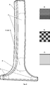
Ausführungsbeispiel 2 B-Säule (Fig. 8)Embodiment 2 B-pillar (Fig. 8)
Das Verstärkungsfasergeflecht besteht aus Kohlenstofffasern, IMS65, 12k. Die Faserzahl beträgt 160. Als Matrixmaterial wird Polypropylen (PP) eingesetzt.The reinforcing fiber braid is made of carbon fibers, IMS65, 12k. The number of fibers is 160. The matrix material used is polypropylene (PP).
Die Struktur der B-Säule wird in verschiedene Bereiche mit unterschiedlichen Anforderungen aufgeteilt, für die dann jeweils geeignete Flechtmuster angewendet werden:
- – Bereiche zur Aufnahme der Crashenergie (viele Kreuzungspunkte) (Muster A),
- – Bereiche hoher Steifigkeit und Festigkeit für Leichtbau (kaum Kreuzungspunkte), es sind keine Flechtwinkeländerungen und keine komplexen Formänderungen notwendig (Muster C),
- – Bereiche mit höherer Geometriekomplexität und Durchmesserunterschieden (mäßige Anzahl an Kreuzungspunkten); Bereich des T-Stoßes, der nicht ohne Kreuzungspunkte gefertigt werden kann, jedoch eine möglichst hohe Steifigkeit und Festigkeit aufweisen soll (Muster B),
- – Anbindung z.B. für Gurt bringt hohe Beanspruchung senkrecht zur Faserrichtung, hohe Sicherheit bei Crash notwendig (viele Kreuzungspunkte); erhöhte Duktilität und Crashenergieaufnahme notwendig (Muster A).
- - areas for recording the crash energy (many crossing points) (pattern A),
- Areas of high rigidity and strength for lightweight construction (hardly crossing points), no braiding angle changes and no complex changes in shape are necessary (sample C),
- - areas with higher geometry complexity and diameter differences (moderate number of crossing points); Area of the T-joint, which can not be manufactured without crossing points, but should have the highest possible rigidity and strength (sample B),
- - Connection eg for belt brings high stress perpendicular to the fiber direction, high safety in crash necessary (many crossing points); increased ductility and Crashenergieaufnahme necessary (sample A).
Die Flechtmuster A, B und C entsprechend den für die Venturidüse beschriebenen.The braiding patterns A, B and C correspond to those described for the Venturi nozzle.
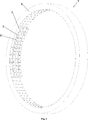
Ausführungsbeispiel 3 Tank (Fig. 9)
Das Verstärkungsfasergeflecht wird aus Kohlenstofffaser, STS40, 24k mit einer Faserzahl von 200 hergestellt. Als Matrixmaterial kommt Epoxidharz zum Einsatz.The reinforcing fiber braid is made of carbon fiber, STS40, 24k with a fiber count of 200. The matrix material used is epoxy resin.
Im zylindrischen Bereich gewährleisten viele Fasern eine hohe Festigkeit und eine geringe Gesamtverformung. (Muster C)In the cylindrical area, many fibers ensure high strength and low overall deformation. (Sample C)
Im Übergang vom zylindrischen Bereich zum Polbereich erfolgt eine starke Veränderung des Flechtwinkels. Möglichst viele Kreuzungspunkte verhindern ein Verrutschen der Fasern auf dem Kern. Es wird ein hoher Bedeckungsgrad angestrebt, um eine hohe Bauteilfestigkeit zu erreichen (Muster A).In the transition from the cylindrical region to the pole region there is a strong change in the braiding angle. As many crossing points as possible prevent the fibers from slipping on the core. A high degree of coverage is sought in order to achieve high component strength (sample A).
An den runden Endbereichen (Polen) erfolgt eine Reduzierung der Faserzahl bis auf 40 (Muster B1, B2). Es sind weniger Fasern notwendig um den kleineren Durchmesser realisieren zu können, ohne eine Aufdickung des Geflechts hervorzurufen. Die Anzahl der Fasern kann so variiert werden, dass die Lagendicke über den runden Endbereich je nach Anforderungsprofil eingestellt werden kann. Es ist somit eine sehr homogene Gestaltung der Polkappenkontur möglich.At the round end areas (Poland), the number of fibers is reduced to 40 (samples B1, B2). Fewer fibers are needed to realize the smaller diameter without causing thickening of the braid. The number of fibers can be varied so that the layer thickness can be adjusted over the round end depending on the requirements. It is thus possible a very homogeneous design of the Polkappenkontur.
Die Flechtmuster A, B und C entsprechend den für die Venturidüse beschriebenen, wobei das Muster B in Muster B1 und B2 aufgeteilt ist und wobei gilt, dass die Faserzahl von Muster B2 kleiner ist als die von B1.The braiding patterns A, B and C correspond to those described for the Venturi nozzle, the pattern B being divided into patterns B1 and B2, and it being understood that the number of fibers of pattern B2 is smaller than that of B1.
BezugszeichenlisteLIST OF REFERENCE NUMBERS
- 11
- Flechtrad braiding
- 22
- Getriebeeinheit der Transportscheibe (Flügelrad) Transmission unit of the transport disc (impeller)
- 2a2a
- Getriebeeinheit der Transportscheibe in Parkbereich für Spulenträgher Transmission unit of the transport disc in the parking area for bobbin carriers
- 33
- Transportscheibe (Flügelrad) Transport disc (impeller)
- 3a3a
- Transportscheibe (Flügelrad) in Parkbereich für Spulenträger Transport disc (impeller) in parking area for coil carrier
- 3131
- Nut in der Transportscheibe zur Bewegung der Spulenträger Groove in the transport disc for moving the coil carriers
- 44
- Stehfaden filler thread
- 55
- ringförmiger Träger der Radialflechtmaschine annular carrier of the radial braiding machine
ZITATE ENTHALTEN IN DER BESCHREIBUNG QUOTES INCLUDE IN THE DESCRIPTION
Diese Liste der vom Anmelder aufgeführten Dokumente wurde automatisiert erzeugt und ist ausschließlich zur besseren Information des Lesers aufgenommen. Die Liste ist nicht Bestandteil der deutschen Patent- bzw. Gebrauchsmusteranmeldung. Das DPMA übernimmt keinerlei Haftung für etwaige Fehler oder Auslassungen.This list of the documents listed by the applicant has been generated automatically and is included solely for the better information of the reader. The list is not part of the German patent or utility model application. The DPMA assumes no liability for any errors or omissions.
Zitierte PatentliteraturCited patent literature
- DE 102009051459 A1 [0003] DE 102009051459 A1 [0003]
- DE 3344866 A1 [0004] DE 3344866 A1 [0004]
- DE 102006006337 A [0005] DE 102006006337 A [0005]
- EP 724034 B1 [0007] EP 724034 B1 [0007]
Claims (8)
Priority Applications (1)
| Application Number | Priority Date | Filing Date | Title |
|---|---|---|---|
| DE201210205906 DE102012205906A1 (en) | 2012-04-11 | 2012-04-11 | Method for manufacturing dynamic braid pattern for fiber reinforcement element of fiber composite component, involves changing number of nodes with fiber strands or number of fiber strands with constant number of nodes in various regions |
Applications Claiming Priority (1)
| Application Number | Priority Date | Filing Date | Title |
|---|---|---|---|
| DE201210205906 DE102012205906A1 (en) | 2012-04-11 | 2012-04-11 | Method for manufacturing dynamic braid pattern for fiber reinforcement element of fiber composite component, involves changing number of nodes with fiber strands or number of fiber strands with constant number of nodes in various regions |
Publications (1)
| Publication Number | Publication Date |
|---|---|
| DE102012205906A1 true DE102012205906A1 (en) | 2013-10-17 |
Family
ID=49232152
Family Applications (1)
| Application Number | Title | Priority Date | Filing Date |
|---|---|---|---|
| DE201210205906 Withdrawn DE102012205906A1 (en) | 2012-04-11 | 2012-04-11 | Method for manufacturing dynamic braid pattern for fiber reinforcement element of fiber composite component, involves changing number of nodes with fiber strands or number of fiber strands with constant number of nodes in various regions |
Country Status (1)
| Country | Link |
|---|---|
| DE (1) | DE102012205906A1 (en) |
Cited By (12)
| Publication number | Priority date | Publication date | Assignee | Title |
|---|---|---|---|---|
| EP2905366A1 (en) * | 2014-02-06 | 2015-08-12 | Airbus Defence and Space GmbH | Modular element for powering and holding braiding lace and braiding device |
| CN104831472A (en) * | 2015-05-11 | 2015-08-12 | 阚玉华 | Cylindrical three-dimensional weaving platform |
| DE102014223127A1 (en) * | 2014-11-12 | 2016-05-12 | Bayerische Motoren Werke Aktiengesellschaft | Pressure vessel, method for producing a pressure vessel and braiding machine |
| DE102015204826A1 (en) * | 2015-03-17 | 2016-09-22 | Bayerische Motoren Werke Aktiengesellschaft | Pressure vessel and method for producing a pressure vessel |
| CN107187074A (en) * | 2017-07-27 | 2017-09-22 | 北京汽车集团有限公司 | Reduce the method for the U-shaped product deformation of composite |
| EP3351670A1 (en) * | 2017-01-19 | 2018-07-25 | ADMEDES GmbH | Braiding machine with magnetic rotors |
| EP3321403A3 (en) * | 2016-11-11 | 2018-08-01 | ADMEDES GmbH | Braiding machine, crossing piece for a braiding machine and sorting device |
| DE102017219716A1 (en) * | 2017-11-07 | 2019-05-09 | Bayerische Motoren Werke Aktiengesellschaft | Process for producing a braided preform, braiding preform, fiber reinforced component and braiding machine |
| JP2020020392A (en) * | 2018-07-31 | 2020-02-06 | 株式会社豊田自動織機 | Pressure vessel and manufacturing method of pressure vessel |
| JP2020020391A (en) * | 2018-07-31 | 2020-02-06 | 株式会社豊田自動織機 | Pressure vessel and manufacturing method of pressure vessel |
| EP3832189A4 (en) * | 2018-07-31 | 2021-09-15 | Kabushiki Kaisha Toyota Jidoshokki | Pressure vessel and pressure-vessel manufacturing method |
| US11375769B2 (en) | 2017-06-27 | 2022-07-05 | Adidas Ag | Engineered braided tube |
Citations (6)
| Publication number | Priority date | Publication date | Assignee | Title |
|---|---|---|---|---|
| DE3344866A1 (en) | 1983-08-31 | 1985-03-14 | Micafil AG, Zürich | Process for producing a tubular weave and its use |
| EP0249372A2 (en) * | 1986-06-06 | 1987-12-16 | K-2 Corporation | Fiber reinforced braided ski core and method and apparatus for making same |
| EP0724034B1 (en) | 1990-07-12 | 1999-09-22 | Albany International Corp. | Method and apparatus for producing a braid structure |
| DE102006006337A1 (en) | 2006-02-11 | 2007-08-16 | Kümpers GmbH & Co. KG | Spatial textile component structure on high-strength threads, as well as methods for their production |
| EP2189273A1 (en) * | 2007-08-10 | 2010-05-26 | Toyota Jidosha Kabushiki Kaisha | Fiber-reinforced resin member, process for producing the same, and apparatus for producing woven fiber fabric |
| DE102009051459A1 (en) | 2009-10-30 | 2011-05-05 | Audi Ag | Method for manufacturing fiber composite part utilized as upper section of A-column of body of cabriolet-vehicle, involves integrating metallic reinforcement insert in fiber composite part at load critical point |
-
2012
- 2012-04-11 DE DE201210205906 patent/DE102012205906A1/en not_active Withdrawn
Patent Citations (6)
| Publication number | Priority date | Publication date | Assignee | Title |
|---|---|---|---|---|
| DE3344866A1 (en) | 1983-08-31 | 1985-03-14 | Micafil AG, Zürich | Process for producing a tubular weave and its use |
| EP0249372A2 (en) * | 1986-06-06 | 1987-12-16 | K-2 Corporation | Fiber reinforced braided ski core and method and apparatus for making same |
| EP0724034B1 (en) | 1990-07-12 | 1999-09-22 | Albany International Corp. | Method and apparatus for producing a braid structure |
| DE102006006337A1 (en) | 2006-02-11 | 2007-08-16 | Kümpers GmbH & Co. KG | Spatial textile component structure on high-strength threads, as well as methods for their production |
| EP2189273A1 (en) * | 2007-08-10 | 2010-05-26 | Toyota Jidosha Kabushiki Kaisha | Fiber-reinforced resin member, process for producing the same, and apparatus for producing woven fiber fabric |
| DE102009051459A1 (en) | 2009-10-30 | 2011-05-05 | Audi Ag | Method for manufacturing fiber composite part utilized as upper section of A-column of body of cabriolet-vehicle, involves integrating metallic reinforcement insert in fiber composite part at load critical point |
Non-Patent Citations (2)
| Title |
|---|
| CHERIF, Chokri: Textile Werkstoffe für den Leichtbau. Berlin Heidelberg : Springer Verlag, 2011. S. 314, 315. - ISBN ISBN 978-3-642-17991-4 * |
| G. GRAVE, Dr. J. HORN: Flexible und reporduzierbare Preformherstellung mittels Flechttechnik. In: 13. Chemnitzer Textiltechnik Tagung, März 2012, S. 1 - 8. * |
Cited By (20)
| Publication number | Priority date | Publication date | Assignee | Title |
|---|---|---|---|---|
| EP2905366A1 (en) * | 2014-02-06 | 2015-08-12 | Airbus Defence and Space GmbH | Modular element for powering and holding braiding lace and braiding device |
| US10100446B2 (en) | 2014-02-06 | 2018-10-16 | Airbus Defence and Space GmbH | Module element for driving and retaining braiding bobbin carriers and a braiding device |
| DE102014223127A1 (en) * | 2014-11-12 | 2016-05-12 | Bayerische Motoren Werke Aktiengesellschaft | Pressure vessel, method for producing a pressure vessel and braiding machine |
| DE102015204826A1 (en) * | 2015-03-17 | 2016-09-22 | Bayerische Motoren Werke Aktiengesellschaft | Pressure vessel and method for producing a pressure vessel |
| CN104831472A (en) * | 2015-05-11 | 2015-08-12 | 阚玉华 | Cylindrical three-dimensional weaving platform |
| EP3321403A3 (en) * | 2016-11-11 | 2018-08-01 | ADMEDES GmbH | Braiding machine, crossing piece for a braiding machine and sorting device |
| US11421358B2 (en) | 2016-11-11 | 2022-08-23 | ADMEDES GmbH | Braiding machine, switch for a braiding machine, and sorting apparatus |
| US11661685B2 (en) | 2017-01-19 | 2023-05-30 | ADMEDES GmbH | High speed braiding machine with magnetic impellers |
| EP3351670A1 (en) * | 2017-01-19 | 2018-07-25 | ADMEDES GmbH | Braiding machine with magnetic rotors |
| US11375769B2 (en) | 2017-06-27 | 2022-07-05 | Adidas Ag | Engineered braided tube |
| CN107187074B (en) * | 2017-07-27 | 2019-03-22 | 北京汽车集团有限公司 | Reduce the method for the U-shaped product deformation of composite material |
| CN107187074A (en) * | 2017-07-27 | 2017-09-22 | 北京汽车集团有限公司 | Reduce the method for the U-shaped product deformation of composite |
| DE102017219716A1 (en) * | 2017-11-07 | 2019-05-09 | Bayerische Motoren Werke Aktiengesellschaft | Process for producing a braided preform, braiding preform, fiber reinforced component and braiding machine |
| US11486070B2 (en) | 2017-11-07 | 2022-11-01 | Bayerische Motoren Werke Aktiengesellschaft | Method for producing a braided preform, braided preform, fiber-reinforced component, and braiding machine |
| JP2020020392A (en) * | 2018-07-31 | 2020-02-06 | 株式会社豊田自動織機 | Pressure vessel and manufacturing method of pressure vessel |
| JP2020020391A (en) * | 2018-07-31 | 2020-02-06 | 株式会社豊田自動織機 | Pressure vessel and manufacturing method of pressure vessel |
| EP3832189A4 (en) * | 2018-07-31 | 2021-09-15 | Kabushiki Kaisha Toyota Jidoshokki | Pressure vessel and pressure-vessel manufacturing method |
| JP7040346B2 (en) | 2018-07-31 | 2022-03-23 | 株式会社豊田自動織機 | Pressure vessel and manufacturing method of pressure vessel |
| JP7040347B2 (en) | 2018-07-31 | 2022-03-23 | 株式会社豊田自動織機 | Pressure vessel and manufacturing method of pressure vessel |
| US11549643B2 (en) | 2018-07-31 | 2023-01-10 | Kabushiki Kaisha Toyota Jidoshokki | Pressure vessel and pressure-vessel manufacturing method |
Similar Documents
| Publication | Publication Date | Title |
|---|---|---|
| DE102012205906A1 (en) | Method for manufacturing dynamic braid pattern for fiber reinforcement element of fiber composite component, involves changing number of nodes with fiber strands or number of fiber strands with constant number of nodes in various regions | |
| EP1738005B1 (en) | Method for producing fibre composite semi-finished products by means of a round wickerwork technique | |
| EP1987185B1 (en) | Three-dimensional textile component structure consisting of high-tensile threads and method for producing said structure | |
| DE10259593B4 (en) | Apparatus and method for potting a core | |
| DE4103908A1 (en) | BRAIDED REINFORCEMENT FOR TUBULAR PIPES, e.g. TUBES, AND METHOD AND DEVICE FOR PRODUCING SUCH A REINFORCEMENT | |
| EP2665600B1 (en) | Method for producing a tubular fiber arrangement of a fiber-reinforced composite part and tubular fiber arrangement | |
| EP2361752B1 (en) | Fibre compound component and method for manufacturing the same | |
| EP2247435B1 (en) | Method and device and the use thereof for producing a fiber composite part | |
| DE102014016832B3 (en) | Braiding device and braiding method for braiding a braided core | |
| DE2302206C2 (en) | Low-friction sliding layer material for bearings | |
| EP0442092B1 (en) | Method of manufacturing fibre reinforced products | |
| WO2020016257A1 (en) | Method for producing a hollow profile having variable curvatures and cross-sections | |
| EP3142843B1 (en) | Method for producing a damper tube from a composite fiber material for a vibration damper | |
| DE102015214909A1 (en) | Flechtpultrusionsvorrichtung for producing a fiber-reinforced plastic hollow profile | |
| DE102010021371B4 (en) | braider | |
| DE102013111702A1 (en) | Fiber composite component and method for producing a fiber composite component | |
| DE4004473A1 (en) | Composite component prodn. with braided and unidirectional fibres | |
| EP2492111A1 (en) | Use of a braiding device, method for producing a rim with a separable braiding device and bicycle rim | |
| DE102012222762A1 (en) | Braiding machine for manufacturing braided fabric structures, has ring-shaped structure arranged in section between discharge eyelets of bobbins and braiding ring, where outer diameter of structure is larger than inner diameter of ring | |
| DE102019104427A1 (en) | Tubular semi-finished fiber product, fiber-reinforced plastic hollow profile, method for producing a fiber semi-finished product and method for producing a fiber-reinforced plastic hollow profile | |
| DE4324973C2 (en) | Process and device for the continuous production of reinforcements for hoses and other elongated hollow bodies | |
| DE102011104430A1 (en) | Apparatus for manufacturing braided fabric used for mountain climbing rope, has center extension portions that are extended transversely to division plane with control portions | |
| EP2832906A1 (en) | Fabric, method and device for its manufacture | |
| DE1960595A1 (en) | Laminated masts from polyester resin impreg - nated glass fibre tows or rovings | |
| DE102007033552B3 (en) | Flexible fiber composite rod for fuel lines comprises a round foam core rod with a molded body with a taper as inner support element on one side |
Legal Events
| Date | Code | Title | Description |
|---|---|---|---|
| R012 | Request for examination validly filed | ||
| R016 | Response to examination communication | ||
| R120 | Application withdrawn or ip right abandoned |