EP0249233A2 - Verfahren und Vorrichtung zur Kohlenvergasung - Google Patents
Verfahren und Vorrichtung zur Kohlenvergasung Download PDFInfo
- Publication number
- EP0249233A2 EP0249233A2 EP87108457A EP87108457A EP0249233A2 EP 0249233 A2 EP0249233 A2 EP 0249233A2 EP 87108457 A EP87108457 A EP 87108457A EP 87108457 A EP87108457 A EP 87108457A EP 0249233 A2 EP0249233 A2 EP 0249233A2
- Authority
- EP
- European Patent Office
- Prior art keywords
- coal
- oxygen
- gas
- air
- pressure
- Prior art date
- Legal status (The legal status is an assumption and is not a legal conclusion. Google has not performed a legal analysis and makes no representation as to the accuracy of the status listed.)
- Withdrawn
Links
Images


Classifications
-
- C—CHEMISTRY; METALLURGY
- C10—PETROLEUM, GAS OR COKE INDUSTRIES; TECHNICAL GASES CONTAINING CARBON MONOXIDE; FUELS; LUBRICANTS; PEAT
- C10J—PRODUCTION OF PRODUCER GAS, WATER-GAS, SYNTHESIS GAS FROM SOLID CARBONACEOUS MATERIAL, OR MIXTURES CONTAINING THESE GASES; CARBURETTING AIR OR OTHER GASES
- C10J3/00—Production of combustible gases containing carbon monoxide from solid carbonaceous fuels
- C10J3/02—Fixed-bed gasification of lump fuel
- C10J3/06—Continuous processes
- C10J3/16—Continuous processes simultaneously reacting oxygen and water with the carbonaceous material
-
- C—CHEMISTRY; METALLURGY
- C10—PETROLEUM, GAS OR COKE INDUSTRIES; TECHNICAL GASES CONTAINING CARBON MONOXIDE; FUELS; LUBRICANTS; PEAT
- C10J—PRODUCTION OF PRODUCER GAS, WATER-GAS, SYNTHESIS GAS FROM SOLID CARBONACEOUS MATERIAL, OR MIXTURES CONTAINING THESE GASES; CARBURETTING AIR OR OTHER GASES
- C10J3/00—Production of combustible gases containing carbon monoxide from solid carbonaceous fuels
- C10J3/46—Gasification of granular or pulverulent flues in suspension
- C10J3/466—Entrained flow processes
-
- C—CHEMISTRY; METALLURGY
- C10—PETROLEUM, GAS OR COKE INDUSTRIES; TECHNICAL GASES CONTAINING CARBON MONOXIDE; FUELS; LUBRICANTS; PEAT
- C10J—PRODUCTION OF PRODUCER GAS, WATER-GAS, SYNTHESIS GAS FROM SOLID CARBONACEOUS MATERIAL, OR MIXTURES CONTAINING THESE GASES; CARBURETTING AIR OR OTHER GASES
- C10J3/00—Production of combustible gases containing carbon monoxide from solid carbonaceous fuels
- C10J3/46—Gasification of granular or pulverulent flues in suspension
- C10J3/48—Apparatus; Plants
- C10J3/50—Fuel charging devices
-
- C—CHEMISTRY; METALLURGY
- C10—PETROLEUM, GAS OR COKE INDUSTRIES; TECHNICAL GASES CONTAINING CARBON MONOXIDE; FUELS; LUBRICANTS; PEAT
- C10J—PRODUCTION OF PRODUCER GAS, WATER-GAS, SYNTHESIS GAS FROM SOLID CARBONACEOUS MATERIAL, OR MIXTURES CONTAINING THESE GASES; CARBURETTING AIR OR OTHER GASES
- C10J2300/00—Details of gasification processes
- C10J2300/09—Details of the feed, e.g. feeding of spent catalyst, inert gas or halogens
- C10J2300/0953—Gasifying agents
- C10J2300/0956—Air or oxygen enriched air
-
- C—CHEMISTRY; METALLURGY
- C10—PETROLEUM, GAS OR COKE INDUSTRIES; TECHNICAL GASES CONTAINING CARBON MONOXIDE; FUELS; LUBRICANTS; PEAT
- C10J—PRODUCTION OF PRODUCER GAS, WATER-GAS, SYNTHESIS GAS FROM SOLID CARBONACEOUS MATERIAL, OR MIXTURES CONTAINING THESE GASES; CARBURETTING AIR OR OTHER GASES
- C10J2300/00—Details of gasification processes
- C10J2300/09—Details of the feed, e.g. feeding of spent catalyst, inert gas or halogens
- C10J2300/0953—Gasifying agents
- C10J2300/0959—Oxygen
-
- C—CHEMISTRY; METALLURGY
- C10—PETROLEUM, GAS OR COKE INDUSTRIES; TECHNICAL GASES CONTAINING CARBON MONOXIDE; FUELS; LUBRICANTS; PEAT
- C10J—PRODUCTION OF PRODUCER GAS, WATER-GAS, SYNTHESIS GAS FROM SOLID CARBONACEOUS MATERIAL, OR MIXTURES CONTAINING THESE GASES; CARBURETTING AIR OR OTHER GASES
- C10J2300/00—Details of gasification processes
- C10J2300/12—Heating the gasifier
- C10J2300/1223—Heating the gasifier by burners
-
- C—CHEMISTRY; METALLURGY
- C10—PETROLEUM, GAS OR COKE INDUSTRIES; TECHNICAL GASES CONTAINING CARBON MONOXIDE; FUELS; LUBRICANTS; PEAT
- C10J—PRODUCTION OF PRODUCER GAS, WATER-GAS, SYNTHESIS GAS FROM SOLID CARBONACEOUS MATERIAL, OR MIXTURES CONTAINING THESE GASES; CARBURETTING AIR OR OTHER GASES
- C10J2300/00—Details of gasification processes
- C10J2300/16—Integration of gasification processes with another plant or parts within the plant
- C10J2300/1678—Integration of gasification processes with another plant or parts within the plant with air separation
Definitions
- This invention relates to a coal gasifier. More particularly, it relates to a coal gasification process and apparatuses therefor in which coal or other hydrocarbons carried with a gas generated by an air separating apparatus is supplied into a coal gasifying oven together with a gasifying agent also generated by said air separating apparatus and they are reacted under a high temperature and high pressure to produce a combustible gas.
- Coal is a useful energy source with abundant reserves, but as it is solid and contains a high percentage of ash, its fields of use are limited in comparison with petroleum and natural gas. However, if coal is converted into gas or liquid, its fields of use will expand greatly and it will become a very useful energy source. In view of such potentialities of coal, the researchers in many countries have made efforts for the development of coal fluidization techniques.
- coal For gasification of coal, coal is broken into fine pieces and supplied into a high-temperature gasification oven together with an oxidizing agent. In the high-temperature oven, coal is reacted to cause a gasification reaction such as partial oxidation, thereby producing a combustible gas mainly composed of carbon monoxide and hydrogen.
- a gasification reaction such as partial oxidation
- the gasification oven efficiency is good since the oxidizing agent is entirely reacted.
- the production cost of oxygen adds to the power generation cost.
- the gasification oven efficiency is low because of supply of non-reactive air as oxidizing agent, but the power generation cost is reduced as no oxygen production cost is required.
- PSA Pressure Swing Adsorption
- Coal gasification does not require oxygen of extremely high purity.
- the internal temperature of the oven rises when using an oxygen-enriched air which would be only slightly higher in oxygen concentration than the air. Therefore, in the case of gasification in entrained state for instance, the ash produced coal in the oven can be easily melted, so that there is no need of effecting rise of temperature by unduly promoting the combustion reaction, and accordingly the gasification efficiency increases. Also, since the partial pressure of oxygen rises, the reaction is promoted to enhance the gasification efficiency.
- An application of PSA to the production of oxygen-enriched air by making use of said principle is disclosed in Japanese Patent Application Kokai (Laid-Open) No. 50298/76.
- nitrogen is produced along with oxygen, so that this nitrogen can be utilized as coal carrier gas.
- the gas discharged on generation of oxygen although high in nitrogen concentration as compared with air, is also high in oxygen concentration and can not be used as carrier gas. Accordingly, it is necessary to introduce nitrogen for carrying coal from a different plant or to build up a nitrogen producing plant beside the plant for producing the oxidizing agent. Naturally, this elevates the whole plant cost, resulting in a substantial rise of power generating cost.
- the present invention was achieved as a result of studies on PSA from its basic principle for solving said problems.
- This invention relates to an application of PSA for coal gasification which makes it possible to produce gas of materials such as oxidizing agent used for a large volume of coal gasification with a very small apparatus, and a coal gasifier making use of said PSA which enables a phenomeral improvement of working efficiency of the whole system.
- the method of this invention because of use of pressurized air for generating high-concentration nitrogen gas, it is possible to form a large volume of gas with the towers of a small capacity, and the oxygen adsorbed on the adsorbent is desorbed under a pressure lower than said air pressure for the regeneration of towers while the produced oxygen-enriched air is used as gasifying agent, so that the system suffers from no loss and its working efficiency can be improved.
- FIG. 2 there is shown a simple flow chart of a coal gasifier.
- the gases necessary for the coal gasifier are shown in Table 2.
- the ratio of oxidizing agent for coal gasification to coal feed is preferably so set that it will give the highest cold gas efficiency.
- the cold gas efficiency represents the ratio of calorific value of coal supplied to that of the gas produced.
- coal gasification basically comprises a partial gasification reaction expressed by the following formula:
- coal is represented by hydrocarbon, with other components such as ash being excluded for the sake of simplicity.
- the calorific value of the produced gas becomes the highest when carbon in coal has been entirely turned into carbon monoxide. Since this reaction is exothermic, it proceeds without heat being applied from the outside.
- the produced gas has a prescribed level of calorific value, it is weakened by nitrogen, an inert gas, contained in the air, making it unable to raise the internal temperature of the oven, resulting in a lowered gasification reaction rate, hence, a reduced gasification rate.
- the oxygen concentration thereof is 5% or less in view of the concept of spontaneous ignition.
- the pressure necessary for the carriage of coal varies greatly depending on coal feed and volume of carrier gas, but generally a pressure of several atm. is required.
- oxygen is adsorbed by utilizing a combined force of oven pressure and differential pressure of carriage to generate high-purity nitrogen and this is used as the gas for carrying coal, while adsorbed oxygen is desorbed by making use of oven pressure to generate oxygen-enriched air which is used as oxidizing agent for coal gasification.
- Fig. 3 shows a flow chart of the PSA system.
- a gas of the prescribed composition is adsorbed under high pressure and desorbed under low pressure. Therefore, the purge gas of low pressure is too high in concentration of said gas of prescribed composition, while the gas taken out under high pressure is too low in concentration of said prescribed composition gas.
- nitrogen is adsorbed by using a zeolite type adsorbent to generate a gas with high oxygen concentration.
- the oxygen-enriched air produced by such method is unfavorable for use in coal gasification.
- the gas obtained by the nitrogen adsorption type oxygen-enriched air producing method is shown in Table 3.
- the gas produced by PSA is very bad in compatibility as compared with said gas required for gasification.
- the product gas is too high in oxygen concentration to use as coal carrier gas. Therefore, for use of such product gas, it must be again introduced into another PSA unit to further elevate the nitrogen concentration. This method is unfavorable as the system is complicated. Also, there exists no other utility which requires gas with oxygen concentration of about 10%.
- oxygen-enriched air to be used as gasifying agent which is essentially required in a great amount, is produced only in a small amount, while nitrogen-enriched gas to be used as coal carrier gas, which is actually needed in a small amount, is produced in bulk.
- Pressurization is a measure for enlarging capacity. In this case, however, since a large volume of gas is wasted, a substantial portion of pressurized energy goes for nothing, resulting in an elevated cost. The conventional system also had the serious defect that the inside pace of the tower is not used effectively because of retention of non gas in the tower.
- PSA which has been generally used for the production of concentrated oxygen is very irrational for application to coal gasification.
- the present inventors have made a complete about-face in conception and invented PSA with remarkably high adaptability to coal gasification. By using this new type of PSA, a high-efficiency power generation system was deviced.
- the gas (1) necessary for coal gasification (Table 2) is oxygen-enriched gas and therefore corresponds to the gas produced by PSA (Table 3), but the former (1) is low in pressure (gasification oven pressure) and required in a large amount, while the latter (3) is just contrary; it is high is pressure and produced only in small quantities. This accounts for the poor adaptability of PSA gas to coal gasification.
- the adsorbents currently used for PSA include oxygen adsorbing type beside the above-mentioned nitrogen adsorbing type. Since the nitrogen adsorbing type has the problems such as mentioned above, studies are being made on the application of oxygen adsorbing type to coal gasification.
- the presently used oxygen adsorbing type PSA is designed for production of pure nitrogen and very high in efficiency. According to this PSA, oxygen is adsorbed at a very low rate, and after oxygen has been adsorbed sufficiently, nitrogen of high purity is produced. The process thereof is exemplified in Fig. 4. For making the nitrogen concentration of the product gas 99.9% or higher, approximately 20 times as much amount of feedstock gas as the product gas is wasted.
- the waste gas used as oxydizing agent is too low in oxygen concentration and also too short in amount. Also, since adsorption is effected at low rate, the system is necessarily enlarged and can not be applied to gasification where a large volume of gas is required.
- the present inventors have adandoned the idea of having the gas adsorbed with nitrogen and instead tried to have the gas adsorbed with oxygen and use this oxygen-adsorbed gas as coal carrier gas in coal gasification, while also trying use of purge gas as gasifying agent for coal gasification.
- An outline of this new scheme is shown in Fig. 5.
- oxygen is adsorbed in a large amount in the initial phase and because of small adsorption of nitrogen, oxygen alone is adsorbed from the gas which has passed the towers to elevate the nitrogen concentration, so that if the desorbing operation is commenced at a time when the adsorption of nitrogen is still small, there is obtained almost the same effect as when oxygen was adsorbed selectively.
- the apparatus is composed of an air separating apparatus, a coal feeding apparatus and a coal gasifying oven.
- the air separating apparatus comprises a compressor 18 for supplying air, an adsorption/desorption tower A 11 capable of performing both adsorption and desorption of gas, valves 23, 27 and 29 designed to periodically oven or close the passage of gas from or to said adsorption/desorption tower A 11 to or from other units, another adsorption/desorption tower B 12 having the same function as A 11, and valves 24, 28 and 30.
- Packed in said towers is an adsorbent which is capable of adsorbing oxygen selectively in bulk or at high speed.
- the coal feeding apparatus is composed of a pressurized hopper 10 in which coal 1 is reservoired in a pressurized state, a feed hopper 13 in which coal 1 is pressurized to a level suitable for supply, a metering feeder 14 of coal 1, a mixer 15 for mixing coal 1 and its carrier gas, valves 22, 26 and 21 for further pressurizing coal 1, and an adjuster 31 for controlling the amount of carrier gas supplied.
- the coal gasifier over is composed of the oven body and a coal burner 17.
- Air 4 taken in is first cleared of dust as it passed through a filter provided at the inlet of compressor 18 and then pressurized by said compressor 18.
- the level of pressure to which air is pressurized is so set that it will be higher than the pressure combining the pressure P1 capable of effecting sufficient supply of carrier gas to the coal feed hopper 13 and ejector 15 and the pressure loss ⁇ P P suffered when gas is passed through the adsorption/desorption towers 11, 12 packed with the adsorbent.
- Pressurized air is supplied into adsorption/desorption towers 11, 12 through valves 29 and 30, respectively.
- PSA functions to repeat adsorption and desorption according to the change of pressure in said towers 11, 12.
- the pressures in said towers 11, 12 are decided by the valves 23, 24, 27, 28, 29 and 30.
- the patterns of opening and closing of the respective valves corresponding to the cycle of operation are shown in Table 4.
- valve 29 is opened to supply pressurized air directly from compressor 18 into adsorption/desorption tower 11, so that the internal pressure of adsorption/desorption tower A 11 is elevated, and accordingly oxygen is selectively adsorbed by the adsorbent packed in the inside of said tower A 11, that is, an adsorbing operation is conducted in said adsorption/desorption tower A 11.
- the gas sent from said tower A 11 to the coal feed and carriage system through valve 23 is low in oxygen content, that is, high in nitrogen content, and is therefore suited as a coal carrier gas with no possibility of causing spontaneous ignition of coal.
- adsorption/desorption tower A 11 becomes unable to perform selective adsorption of oxygen.
- adsorption/desorption tower is packed with MSC, an adsorbent which is capable of adsorbing oxygen selectively at a higher rate than nitrogen. Therefore, it is not that the tower became incapable of further performing oxygen adsorption only because the equilibrium adsorption of the adsorbent has been reached. This reason will be explained with reference to the basic performance curves of MSC shown in Fig. 6. In the graph of Fig.
- the elapsed time from start of adsorbing operation is plotted as abscissa and the amount of gas adsorbed per 1g of absorbent as ordinate.
- MSC shows an almost equal equilibrium adsorption for both oxygen and nitrogen, but the initial adsorbing rate differs greatly between oxygen and nitrogen, that is, as seen from the graph, the oxygen adsorbing rate is far higher than the nitrogen adsorbing rate in the initial phase of operation.
- the oxygen adsorption is greater than the nitrogen adsorption, and consequently oxygen is adsorbed selectively.
- nitrogen begins to be adsorbed, too, so that selectivity is lost. Based on these facts, the time of switching from the adsorbing operation to the desorbing operation is decided.
- the operating cycle 1 is switched to the cycle 2 where the desorbing operation is conducted in said tower A 11.
- the produced gas switchover valve 23 and the valve 29 for supplying air (feedstock gas) into tower A 11 are closed at the same time, while the purge gas switchover valve 27 is opened.
- adsorption/desorption tower A 11 is communicated with burner 17 which supplies the gasifying agent into coal gasifying oven 16. Since adsorption/desorption tower A 11 is set to a higher pressure than oven 16, the gas in said tower A 11 flows into oven 16 and the pressure in the tower A 11 begins to lower.
- the adsorbent in said tower A 11 is adsorbed with a large volume of oxygen by the adsorbing operation under a high pressure.
- Oxygen adsorbed by the adsorbent in said tower A 11 is desorbed by said operation of lowering the pressure in said tower A 11.
- the oxygen concentration of the gas supplied into oven 16 as gasifying agent becomes higher than air 4 (feedstock gas), thus forming so-called oxygen-enriched air.
- an agent for selectively adsorbing oxygen As the agent for selectively adsorbing oxygen, there can be used those obtained by metallizing zeolite type adsorbents. The adsorbing performance of such agents is shown in Fig. 7. Since these agents are different in equilibrium adsorption of oxygen and nitrogen, they are advantageous over MSC in that there exist no restrictive conditions on agent performance in application to PSA.
- Coal carrier gas is supplied into pressurized hopper 10 via valve 22 and into feed hopper 13 via valve 26. It is also supplied into ejector 15 via valve 31 having a flow rate regulating function. Coal 1 is crushed and classified into particle sizes convenient for gasification in oven 16 and then supplied to pressurized coal hopper 10.
- valve 25 is closed while valve 31 is opened to keep the pressurized hopper 10 under normal pressure, and in this state coal 1 is led into said hopper 10. Then, valve 31 is closed and valve 22 is opened to supply the carrier gas to the hopper and pressurize it. When the gas was pressurized equally to the previously pressurized feed hopper 13, valve 25 is opened to supply coal 1 from said pressurized hopper 10 into feed hopper 13. Thereafter, valve 25 is closed and valve 21 is opened to vent out carrier gas in pressurized hopper 10 and bring pressurized feed hopper 13 into normal pressure to resume the initial mode of operation.
- Coal 1 filled in feed hopper 13 is led into ejector 15 through metering rotary feeder 14.
- coal 1 is mixed with the carrier gas adjusted in its flow rate by flow regulating valve 31, and sent to burner 17 through a conduit.
- burner 17 coal is mixed with the oxidizing agent and passed into oven 16.
- coal 1 is reacted with the oxydizing agent and gasified to form a combustible gas. Since oxygen-enriched air is used as the gasifying agent, the inside of the oven can be made higher in temperature than when using ordinary air, so that the ash in coal 1 can be melted even when gasification is conducted at a lower oxygen/coal ratio, and therefore the gasification efficiency is improved.
- the ratio of the produced amount of oxygen-enriched air to the produced amount of carrier gas is variable depending on the cycle interval, space velocity of the adsorption/desorption tower, and other factors, but the range of operation corresponding to the necessary gas composition can be determined to a certain extent by calculations.
- Fig. 8 The relation between production of gasifying agent and oxygen concentration of gasifying agent at selected nitrogen concentrations (99.9%, 99%, 95% and 90%) of carrier gas is shown in Fig. 8.
- the oxygen concentration of oxygen-enriched air (gasifying agent) is plotted as abscissa and the ratio of produced amount of gasifying agent to stockfeed gas (air) as ordinate.
- a desired relation can be obtained by properly selecting the adsorption/desorption switchover cycle in the tower or by changing the working pressure for the adsorbing and desorbing operations.
- nitrogen concentration of carrier gas can be raised by shortening the adsorption time and switching adsorption and desorption at an earlier period. It is also possible to raise nitrogen concentration of carrier gas by enlarging the difference in working pressure between adsorbing and desorbing operations.
- the gasifying agent with 20% oxygen concentration is equal to air which has undergone no oxygen enrichment. In this case, therefore, there is produced no nitrogen as carrier gas and the whole amount of gas can be used as gasifying agent.
- nitrogen concentration of carrier gas When nitrogen concentration of carrier gas is fixed, the higher the oxygen concentration of gasifying agent, the less becomes the produced amount of gasifying agent. For instance, when nitrogen concentration of carrier gas is 99.9%, if oxygen concentration of gasifying agent is 25%, the ratio of the produced amount of gasifying agent to the amount of feedstock gas will be 80%, the remaining 20% accounting for the produced carrier gas.
- the gasifying gas to carrier gas ratio is preferably about 5 to 1. This ratio corresponds to 80% in terms of ratio of the produced amount of gasifying agent to the amount of feedstock gas. In such a case, oxygen concentration of gasifying agent can be adjusted to about 25% and it becomes possible to sufficiently raise the gasification efficiency.
- a specific effect of this embodiment of the invention is that since the pressure at the time of adsorbing operation in adsorption/desorption towers 11, 12 is regulated to a pressure which enables supply of coal carrier gas, there is no need of further pressuring the gas produced from PSA.
- a compressor is used for pressurizing the gas produced by PSA, but in the case of coal gasification where there are required two different types of gas, viz. coal carrier gas and oxydizing agent, and also these two types of gas differ by about 10 times in amount required, it becomes necessary to use two sets of compressor differing greatly in throughput capacity.
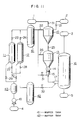
- FIG. 9 An adaptation of the coal gasifying apparatus of this invention to a coal gasification combined power generation system is illustrated in Fig. 9.
- This coal gasification complex power generation system is composed of a coal gasifying oven 16, a gas turbine 110, and air producing equipments 11, 12.
- Said oven 16 and air separating equipments 11, 12 are the same as shown in Fig. 1.
- the gas produced from oven 16 contains unreacted char and harmful sulfur compounds.
- the gas containing unreacted char, etc. is led into a dust removing device such as cyclone, and after cleared of dust therein, this gas is reservoired in hopper 102, then passed through a locked hopper system consisting of hoppers 103 and 104 and recycled into oven 16 from feeder 105.
- the sulfur compounds contained in the gas stream are removed by a desulfurizing device 106. Before entering this desulfurizing device, the gas is lowered in temperature by heat exchanger 107 to a level convenient for desulfurization.
- the dust-removed and desulfurized gas is burned by gas turbine combustor 108 to drive gas turbine 110. Further, steam is produced from the combustion gas by using heat exchanger 109 to drive steam turbine 111. By using the energy produced by driving said turbines, compressor 18 is driven to pressurize air 4 for using it for gasification and combustion of gas in said gas turbine combustor 108.
- the present system also permits a marked reduction in size of air separating equipment as compared with the conventional systems.
- the plottage of the plant is directly associated with the power plant construction cost.
- PSA it has been necessary to set up PSA units for both of coal carrier gas and product gas, and also, in the system using PSA, more than half of the towers must be stopped for the desorbing operation, so that a vast plottage has been required for the plant construction.
- the present invention since the whole of gas supplied to PSA can be utilized effectively, a drastic reduction in size of equipments is made possible as compared with the conventional systems.
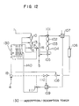
- the flow chart of this embodiment is substantially the same as that of the first embodiment, but in this embodiment, the operating pressure of the adsorption/desorption towers is low, and the produced oxygen-enriched air and coal carrier gas are pressurized by boost-up compressors 38 and 39, respectively.
- PSA is conducted at a low temperature and under a low pressure.
- the adsorbed gas can be desorbed more effectively under a lower pressure, resulting in a higher working efficiency.
- the specific effect of this embodiment consists in the easy adsorbing and desorbing operations.
- buffer tank 41 is provided behind outlet valves 23, 24 of the gas which has undergone the adsorbing operation, that is, high-purity nitrogen gas used as carrier gas, and another buffer tank 42 is provided behind outlet valves 27, 28 of the gasifying agent which had undergone the desorbing operation.
- adsorption tower 43 packed with an agent for removing moisture of air 4 after it has been pressurized by compressor 18.
- the adsorbing and desorbing operations are performed by changing the internal pressures of adsorption/desorption towers A 11 and B 12 by operating valves 23 - 24 and 27 - 30. Therefore, a large variation of pressure is produced in the outlet gas of adsorption/desorption towers A 11 and B 12.
- the desorption of oxygen from the adsorbent is not yet sufficient, therefore the oxygen concentration of the produced oxygen-enriched air is low.
- the oxygen concentration of the oxygen-enriched air is high.
- buffer tanks 41, 42 such variations of pressure or composition of the gas produced by the adsorbing and desorbing operations are to be eliminated by buffer tanks 41, 42.
- Adsorption tower 43 for removing air moisture which is another difference of this embodiment from the first embodiment, will now be explained.
- the adsorbent specific to PSA is susceptible to water and badly lowered in its efficiency when even a slight amount of water is contained therein.
- the moisture contained in the air is condensed to adversely affect the performance of the agent packed in adsorption/desorption towers A 11, B 12.
- the specific effect of this embodiment is that the variations of pressure or composition of the gas produced by the adsorbing and desorbing operations are reduced to allow supply of the gasifying agent and carrier gas of the stabilized compositions with a stabilized pressure to improve the operatability of the gasifier.
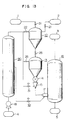
- the flow chart of this embodiment is almost equal to that of the first embodiment shown in Fig. 7. The differences are that the adsorption/desorption towers in the air separating system are provided in multiple stages, and that the gas produced in the oven is used for the desorbing operation.
- the adsorbing and desorbing operations are repeated alternately as said above, and these repetitive operations cause instabilization of the outlet gas composition and the outlet pressure.
- the coal gasifier designed for power generation has a high throughput, and it is impossible to supply the whole amount of gas required for coal gasification by one unit of PSA.
- plurality of adsorption/desorption towers 130 are provided so that said repetitive operations may be performed continuously by slightly staggering the time of operation for each tower. This can eliminate instability of the outlet gas composition and the outlet pressure, which is the defect of PSA.
- the load variability is improved by providing a plurality of adsorption/desorption towers 130.
- throughput of the gas must be changed by this tower 130 itself for varying the load.
- Such operations impose a restriction to the initial design conditions.
- a plurality of towers are provided as in this embodiment of the invention, when for instance the load is lowered, it is possible to cope with the load variation by merely reducing the number of the towers operated.
- the feature of the present embodiment of the invention resides in that the gas produced in the oven is used for the desorbing operation.
- the low-grade steam which has passed steam turbine 111 in Fig. 9 is led into adsorption/desorption towers 130 via line 140.
- As the low-grade steam there can be used, beside that from said steam turbine, other suitable heat sources such as return circulating water from the water-cooled walls of the oven.
- the heat source led through line 140 is supplied into adsorption/desorption towers 130 in the mode of desorbing operation. Thereby the oxygen adsorbed by the adsorbent is quickly desorbed.
- the desorbed gas serves as the gasifying agent in coal gasification, the gasifying agent is heated to a higher temperature, allowing a rise of internal temperature of the oven to improve the gasification efficiency.
- composition and pressure of the produced gas are stabilized to improve the desorbing efficiency, enabling separation of a gas of higher performance.
- the fifth embodiment of the present invention will be described by referring to Fig. 13. It is expected that the performance of the oxygen adsorbent will be greatly improved in future, and this will enable a drastic reduction in size of the adsorption/desorption tower. In this embodiment of the invention, in anticipation of such future technology, all of the adsorption/desorption towers are assembled into a single air separation tower 90.
- both gasifying agent and coal carrier gas used in coal gasification can be produced at the same time from air without using must energy for the production, so that the equipments required for gasification can be remarkably reduced in size and also the cost of electricity production by coal gas power generation can be reduced.
- Fig. 1 is a flow chart of the first embodiment of this invention.
- Fig. 2 shows a schematic flow chart of the coal gasifier and the compositions of the necessary gases.
- Fig. 3 shows a schematic flow chart of nitrogen adsorbing type PSA and the compositions of the produced gases.
- Fig. 4 shows a schematic flow chart of oxygen adsorbing type PSA and the compositions of the produced gases.
- Fig. 5 shows a schematic flow chart of the system of this invention comprising a combination of coal gasifier and PSA and the compositions of the carrier gases.
- Fig. 6 shows the relation between adsorption of the adsorbent used in the first embodiment and time.
- Fig. 7 shows the adsorbing performance in case of using an agent capable of selectively adsorbing oxygen.
- Fig. 8 is an illustration of the operating conditions of the first embodiment.
- Fig. 9 is a flow chart of the power generating system using coal gasifier of the first embodiment of the invention.
- Fig. 10 is a flow chart of the second embodiment of the invention.
- Fig. 11 is a flow chart of the third embodiment of the invention.
- Fig. 12 is a flow chart of the fourth embodiment of the invention.
- Fig. 13 is a flow chart of the fifth embodiment of the invention.
Landscapes
- Chemical & Material Sciences (AREA)
- Engineering & Computer Science (AREA)
- Combustion & Propulsion (AREA)
- Oil, Petroleum & Natural Gas (AREA)
- Organic Chemistry (AREA)
- Separation Of Gases By Adsorption (AREA)
- Industrial Gases (AREA)
- Oxygen, Ozone, And Oxides In General (AREA)
Applications Claiming Priority (2)
| Application Number | Priority Date | Filing Date | Title |
|---|---|---|---|
| JP133669/86 | 1986-06-11 | ||
| JP13366986A JPH0678531B2 (ja) | 1986-06-11 | 1986-06-11 | 石炭ガス化方法及び装置 |
Publications (2)
| Publication Number | Publication Date |
|---|---|
| EP0249233A2 true EP0249233A2 (de) | 1987-12-16 |
| EP0249233A3 EP0249233A3 (de) | 1988-07-20 |
Family
ID=15110140
Family Applications (1)
| Application Number | Title | Priority Date | Filing Date |
|---|---|---|---|
| EP87108457A Withdrawn EP0249233A3 (de) | 1986-06-11 | 1987-06-11 | Verfahren und Vorrichtung zur Kohlenvergasung |
Country Status (2)
| Country | Link |
|---|---|
| EP (1) | EP0249233A3 (de) |
| JP (1) | JPH0678531B2 (de) |
Cited By (6)
| Publication number | Priority date | Publication date | Assignee | Title |
|---|---|---|---|---|
| EP0334833A1 (de) * | 1988-03-11 | 1989-09-27 | VOEST-ALPINE INDUSTRIEANLAGENBAU GESELLSCHAFT m.b.H. | Verfahren zum Druckvergasen von Kohle für den Betrieb eines Kraftwerkes |
| WO1993023397A1 (en) * | 1992-05-20 | 1993-11-25 | Merrell Dow Pharmaceuticals Inc. | 4-mercaptoacetylamino-[2] benzazepinone(3) derivatives, and use as enkephalinase inhibitors |
| CN1068336C (zh) * | 1993-05-21 | 2001-07-11 | 埃克森化学专利公司 | 流化床中单体聚合方法 |
| CN108774549A (zh) * | 2018-08-29 | 2018-11-09 | 中国石油化工股份有限公司 | 气流床粉煤加氢气化炉、加氢气化系统及加氢气化方法 |
| CN112503521A (zh) * | 2020-11-25 | 2021-03-16 | 西安交通大学 | 一种气化耦合低NOx燃烧系统和低NOx燃烧方法及设计方法 |
| CN114917722A (zh) * | 2022-07-21 | 2022-08-19 | 广州能源检测研究院 | 一种活性炭VOCs气体高温解吸脱附及耦合处理系统 |
Families Citing this family (3)
| Publication number | Priority date | Publication date | Assignee | Title |
|---|---|---|---|---|
| JP2870913B2 (ja) * | 1990-01-12 | 1999-03-17 | 東京電力株式会社 | 粗悪燃料のガス化ガスを燃料とするガスタービン発電方法 |
| US8500877B2 (en) * | 2010-05-17 | 2013-08-06 | General Electric Company | System and method for conveying a solid fuel in a carrier gas |
| CN104165536B (zh) * | 2014-08-21 | 2016-08-24 | 兰州兰洛炼化设备有限公司 | 伴热式煤粉输送、换热、分离装置 |
Citations (3)
| Publication number | Priority date | Publication date | Assignee | Title |
|---|---|---|---|---|
| US3976442A (en) * | 1974-12-18 | 1976-08-24 | Texaco Inc. | Synthesis gas from gaseous CO2 -solid carbonaceous fuel feeds |
| EP0040935A2 (de) * | 1980-05-23 | 1981-12-02 | Mitsubishi Jukogyo Kabushiki Kaisha | Sauerstoff-Adsorbent und seine Anwendung zur Trennung von Sauerstoff und Stickstoff |
| EP0092856A2 (de) * | 1982-04-26 | 1983-11-02 | Shell Internationale Researchmaatschappij B.V. | Verfahren zur Vergasung eines festen kohlenstoffhaltigen Brennstoffes |
-
1986
- 1986-06-11 JP JP13366986A patent/JPH0678531B2/ja not_active Expired - Fee Related
-
1987
- 1987-06-11 EP EP87108457A patent/EP0249233A3/de not_active Withdrawn
Patent Citations (3)
| Publication number | Priority date | Publication date | Assignee | Title |
|---|---|---|---|---|
| US3976442A (en) * | 1974-12-18 | 1976-08-24 | Texaco Inc. | Synthesis gas from gaseous CO2 -solid carbonaceous fuel feeds |
| EP0040935A2 (de) * | 1980-05-23 | 1981-12-02 | Mitsubishi Jukogyo Kabushiki Kaisha | Sauerstoff-Adsorbent und seine Anwendung zur Trennung von Sauerstoff und Stickstoff |
| EP0092856A2 (de) * | 1982-04-26 | 1983-11-02 | Shell Internationale Researchmaatschappij B.V. | Verfahren zur Vergasung eines festen kohlenstoffhaltigen Brennstoffes |
Cited By (9)
| Publication number | Priority date | Publication date | Assignee | Title |
|---|---|---|---|---|
| EP0334833A1 (de) * | 1988-03-11 | 1989-09-27 | VOEST-ALPINE INDUSTRIEANLAGENBAU GESELLSCHAFT m.b.H. | Verfahren zum Druckvergasen von Kohle für den Betrieb eines Kraftwerkes |
| WO1993023397A1 (en) * | 1992-05-20 | 1993-11-25 | Merrell Dow Pharmaceuticals Inc. | 4-mercaptoacetylamino-[2] benzazepinone(3) derivatives, and use as enkephalinase inhibitors |
| AU669716B2 (en) * | 1992-05-20 | 1996-06-20 | Aventis Inc. | 4-mercaptoacetylamino-(2) benzazepinone(3) derivatives, and use as enkephalinase inhibitors |
| CN1068336C (zh) * | 1993-05-21 | 2001-07-11 | 埃克森化学专利公司 | 流化床中单体聚合方法 |
| CN108774549A (zh) * | 2018-08-29 | 2018-11-09 | 中国石油化工股份有限公司 | 气流床粉煤加氢气化炉、加氢气化系统及加氢气化方法 |
| CN108774549B (zh) * | 2018-08-29 | 2023-10-24 | 中国石油化工股份有限公司 | 气流床粉煤加氢气化炉、加氢气化系统及加氢气化方法 |
| CN112503521A (zh) * | 2020-11-25 | 2021-03-16 | 西安交通大学 | 一种气化耦合低NOx燃烧系统和低NOx燃烧方法及设计方法 |
| CN114917722A (zh) * | 2022-07-21 | 2022-08-19 | 广州能源检测研究院 | 一种活性炭VOCs气体高温解吸脱附及耦合处理系统 |
| CN114917722B (zh) * | 2022-07-21 | 2022-10-18 | 广州能源检测研究院 | 一种活性炭VOCs气体高温解吸脱附及耦合处理系统 |
Also Published As
| Publication number | Publication date |
|---|---|
| EP0249233A3 (de) | 1988-07-20 |
| JPS62290794A (ja) | 1987-12-17 |
| JPH0678531B2 (ja) | 1994-10-05 |
Similar Documents
| Publication | Publication Date | Title |
|---|---|---|
| AU2008278730B2 (en) | Method of and a plant for combusting carbonaceous fuel by using a solid oxygen carrier | |
| US10081772B2 (en) | Conversion of carbonaceous fuels into carbon free energy carriers | |
| US5688296A (en) | Control system for IGCC's | |
| CA2590485C (en) | Apparatus and method for controlling compressor motor speed in a hydrogen generator | |
| KR20020054366A (ko) | 탄소질 물질로부터의 수소생성 | |
| CN1795257A (zh) | 能移走co2并产生h2的热固体气化器 | |
| AU2009338632B2 (en) | Method for supplying an entrained-flow gasification reactor with fuel from a reservoir tank | |
| EP0249233A2 (de) | Verfahren und Vorrichtung zur Kohlenvergasung | |
| CN107849462A (zh) | 通过金属氧化物循环还原和氧化的合成气生产 | |
| CN106629600A (zh) | 粗合成气吸附催化制氢工艺及其设备 | |
| EP0444987B1 (de) | Methode zur Reinigung heisser Reduktionsgase und kombiniertes Kraftwerk mit Kohlenvergasung | |
| CA2456699A1 (en) | Liquid fuel synthesis system | |
| US6740258B1 (en) | Process for the production of synthesis gas in conjunction with a pressure swing adsorption unit | |
| US4405561A (en) | Drain and sampling valve assembly for a fluidized bed reactor | |
| JPS63183992A (ja) | Psaによる石炭ガス化方法及び装置 | |
| RU2014882C1 (ru) | Способ получения адсорбента | |
| US20230357005A1 (en) | Redox looping systems and methods for production of oxidized products | |
| WO2023096643A1 (en) | Systems and methods for redox energy recovery | |
| JPS63258986A (ja) | 石炭からの合成燃料ガスの品質を改良する方法および装置 | |
| JPS60118611A (ja) | 並流式二酸化硫黄還元反応器 | |
| CN111057585A (zh) | 煤流化气化的方法 | |
| JPS63168487A (ja) | 石炭ガス化方法および装置 | |
| JPH07114927B2 (ja) | ▲高▼温還元性ガスの精製方法 | |
| JPH0631355B2 (ja) | コ−クス炉ガスからの高発熱量ガスの製造法 | |
| KR850004257A (ko) | 산화물질을 환원시키는 동시에 열에너지로 재생되는데 적절한 가스를 생성시키는 방법 및 장치 |
Legal Events
| Date | Code | Title | Description |
|---|---|---|---|
| PUAI | Public reference made under article 153(3) epc to a published international application that has entered the european phase |
Free format text: ORIGINAL CODE: 0009012 |
|
| AK | Designated contracting states |
Kind code of ref document: A2 Designated state(s): CH DE FR GB IT LI NL SE |
|
| PUAL | Search report despatched |
Free format text: ORIGINAL CODE: 0009013 |
|
| RHK1 | Main classification (correction) |
Ipc: C10J 3/46 |
|
| AK | Designated contracting states |
Kind code of ref document: A3 Designated state(s): CH DE FR GB IT LI NL SE |
|
| 17P | Request for examination filed |
Effective date: 19880722 |
|
| 17Q | First examination report despatched |
Effective date: 19890831 |
|
| STAA | Information on the status of an ep patent application or granted ep patent |
Free format text: STATUS: THE APPLICATION HAS BEEN WITHDRAWN |
|
| 18W | Application withdrawn |
Withdrawal date: 19900312 |
|
| R18W | Application withdrawn (corrected) |
Effective date: 19900312 |
|
| RIN1 | Information on inventor provided before grant (corrected) |
Inventor name: TOMURO, JINICHI Inventor name: HAGA, TETSURO Inventor name: MIYAMOTO, TOMOHIKO Inventor name: YAMADA, RYOOKICHI Inventor name: NOGITA, SHUNSUKE Inventor name: HISHINUMA, YUKIO Inventor name: MORIHARA, ATSUSHI Inventor name: TOMOMURA, MASAOMI Inventor name: KOYAMA, SHUNTARO |