EP0248813B1 - Re-usable casing system for the creation of free spaces in building materials - Google Patents
Re-usable casing system for the creation of free spaces in building materials Download PDFInfo
- Publication number
- EP0248813B1 EP0248813B1 EP86902361A EP86902361A EP0248813B1 EP 0248813 B1 EP0248813 B1 EP 0248813B1 EP 86902361 A EP86902361 A EP 86902361A EP 86902361 A EP86902361 A EP 86902361A EP 0248813 B1 EP0248813 B1 EP 0248813B1
- Authority
- EP
- European Patent Office
- Prior art keywords
- hose
- set forth
- casing system
- liquid
- filled
- Prior art date
- Legal status (The legal status is an assumption and is not a legal conclusion. Google has not performed a legal analysis and makes no representation as to the accuracy of the status listed.)
- Expired
Links
Images

Classifications
-
- E—FIXED CONSTRUCTIONS
- E04—BUILDING
- E04G—SCAFFOLDING; FORMS; SHUTTERING; BUILDING IMPLEMENTS OR AIDS, OR THEIR USE; HANDLING BUILDING MATERIALS ON THE SITE; REPAIRING, BREAKING-UP OR OTHER WORK ON EXISTING BUILDINGS
- E04G15/00—Forms or shutterings for making openings, cavities, slits, or channels
- E04G15/06—Forms or shutterings for making openings, cavities, slits, or channels for cavities or channels in walls of floors, e.g. for making chimneys
- E04G15/063—Re-usable forms
- E04G15/066—Re-usable forms with fluid means to modify the section
-
- B—PERFORMING OPERATIONS; TRANSPORTING
- B28—WORKING CEMENT, CLAY, OR STONE
- B28B—SHAPING CLAY OR OTHER CERAMIC COMPOSITIONS; SHAPING SLAG; SHAPING MIXTURES CONTAINING CEMENTITIOUS MATERIAL, e.g. PLASTER
- B28B7/00—Moulds; Cores; Mandrels
- B28B7/28—Cores; Mandrels
- B28B7/30—Cores; Mandrels adjustable, collapsible, or expanding
- B28B7/32—Cores; Mandrels adjustable, collapsible, or expanding inflatable
-
- E—FIXED CONSTRUCTIONS
- E04—BUILDING
- E04C—STRUCTURAL ELEMENTS; BUILDING MATERIALS
- E04C5/00—Reinforcing elements, e.g. for concrete; Auxiliary elements therefor
- E04C5/01—Reinforcing elements of metal, e.g. with non-structural coatings
- E04C5/06—Reinforcing elements of metal, e.g. with non-structural coatings of high bending resistance, i.e. of essentially three-dimensional extent, e.g. lattice girders
- E04C5/0636—Three-dimensional reinforcing mats composed of reinforcing elements laying in two or more parallel planes and connected by separate reinforcing parts
- E04C5/064—Three-dimensional reinforcing mats composed of reinforcing elements laying in two or more parallel planes and connected by separate reinforcing parts the reinforcing elements in each plane being formed by, or forming a, mat of longitunal and transverse bars
-
- E—FIXED CONSTRUCTIONS
- E04—BUILDING
- E04C—STRUCTURAL ELEMENTS; BUILDING MATERIALS
- E04C5/00—Reinforcing elements, e.g. for concrete; Auxiliary elements therefor
- E04C5/16—Auxiliary parts for reinforcements, e.g. connectors, spacers, stirrups
- E04C5/18—Spacers of metal or substantially of metal
-
- E—FIXED CONSTRUCTIONS
- E04—BUILDING
- E04G—SCAFFOLDING; FORMS; SHUTTERING; BUILDING IMPLEMENTS OR AIDS, OR THEIR USE; HANDLING BUILDING MATERIALS ON THE SITE; REPAIRING, BREAKING-UP OR OTHER WORK ON EXISTING BUILDINGS
- E04G11/00—Forms, shutterings, or falsework for making walls, floors, ceilings, or roofs
- E04G11/04—Forms, shutterings, or falsework for making walls, floors, ceilings, or roofs for structures of spherical, spheroid or similar shape, or for cupola structures of circular or polygonal horizontal or vertical section; Inflatable forms
- E04G11/045—Inflatable forms
Definitions
- the invention relates to a reusable formwork system for the production of free spaces in a building material, comprising at least one hose which is closed at one end and can be filled with a liquid via a filling and emptying valve, which penetrates the building material and determines the free space to be formed, the hose still Solidification of the building material while leaving the respective free space from the solidified building material can be removed for reuse.
- FR-A-1 141 502 it is known to form cavities in building materials by flexible hollow bodies which are closed on one side and which are inserted into the building material and filled with water or compressed air via a filling valve.
- the flexible hollow bodies are connected in the middle to a pull rope at their closed end and can be removed by pulling on the pull rope after the building material has solidified.
- FR-A-1 062 968 discloses a double-walled hollow body for the same purpose, which contains an outer body made of rubberized canvas and an inner body made of soft rubber.
- the inner body is penetrated by a spring and is filled with water. For emptying, the space between the inner body and the outer body is pressurized with compressed air.
- the invention has for its object to provide a reusable formwork system of the type mentioned for the production of open spaces in building materials, which can be used to produce differently designed open spaces and is universally applicable, d. H. can be used on a construction site as well as in the prefabrication of components.
- the invention has the further object to provide a reusable formwork system of the type mentioned for the production of free spaces in building materials, by which the consolidation of the building material is promoted and which provides free spaces with a particularly smooth surface without being impaired in its reusability.
- this object is achieved in that the at least one liquid-filled hose is connected at its open end to a vibrating device.
- liquid-filled hoses has the advantage that the incompressible liquid effectively prevents even locally restricted compression of the hose during the solidification of the building material. Due to the tight contact of the solidifying building material on the liquid-filled hose or the liquid-filled hoses, a particularly uniform and smooth surface of the free space or cavity formed is obtained. At the same time, however, the liquid filling enables vibrations to solidify the building material to be generated by exciting vibrations in the liquid-filled hose.
- the vibrations are advantageously generated by a reciprocating piston, which acts directly on the liquid contained in a liquid-filled hose or in a feed line to which a plurality of hoses are connected in parallel.
- a helical compression spring In order to achieve a better adaptation of the hoses to predetermined shapes of the free spaces such as arches and the like and to reliably rule out the risk of kinks or constrictions, it is expedient to insert a helical compression spring into the hose.
- This helical compression spring has the further important advantage that when a vacuum is applied to empty the hose does not collapse but is supported by the helical compression spring. As a result, the contact surfaces between the solidified building material and the hose are reduced considerably, so that the removal of the hose from the free space or cavity formed is greatly facilitated.
- the hose is provided with a further filler at locations where the free space or cavity is to be connected to the outer surface of the building material is detachably connected at one end to the liquid-filled hose by a clamping device and can be removed and reused after the building material has solidified and the liquid-filled hose has been removed.
- a further free space or cavity is obtained which branches off from the cavity formed by the liquid-filled hose and opens into the outer surface or surface of the building material.
- the laying of the hoses in the building material can be facilitated in the case of reinforced building materials such as concrete in that the reinforced building material is provided with spacers or guide elements for the hose. This ensures that the hose assumes the desired position and does not change this position in the liquid-filled state and during the solidification of the building material.
- the reusable formwork system for the production of open spaces or cavities can be used in many different ways and in connection with a wide variety of building materials.
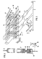
- the embodiment of the reusable formwork system shown schematically in overall perspective view in FIG. 1 is shown in connection with a reinforcement 10 for concrete as a building material.
- Such a reusable formwork system is used for.
- the core of the reusable formwork system according to FIG. 1 is a packing 1, which consists of a series of essentially parallel hoses 2, one end of which is closed by a vent valve 3 according to FIG. 2 and the open ends of which are connected to a common supply line 4 .
- the common feed line 4 is connected via a branch 5 to a filling and emptying valve 6 of conventional design and to a vibrating device 30 described further below in connection with FIG. 2.
- the common supply line 4 is further provided with a safety or overpressure relief valve 7, which automatically relieves the packing 1 from an inadmissibly increased internal pressure.
- the filler 1 or the hoses 2 are inserted into a casing 8 of conventional construction for concrete, and this casing 8 is therefore not shown in detail.
- the filler 1 or the tubes 2 are made of rubber or plastic or another material compatible with concrete, which has a sufficient compressive strength against the internal pressures that occur, but is flexible in order to be able to follow deformations.
- the filler body can also be covered in a conventional manner with a perforated film, which adheres to the solidified or hardened building material when the filler body 1 is removed.
- the reinforcement 10 is provided for a concrete ceiling.
- This reinforcement 10 consists of a first, namely lower structural steel mat 11 and a second, namely upper structural steel mat 12, which are arranged essentially parallel to one another at a distance and are kept at a distance from one another by spacers or guide elements 13.
- the spacers form guide elements 13 for the hoses 2, which either run through the guide elements 13 or between adjacent guide elements 13, the guide elements 13 forming different rows 14 of guide elements 13 arranged one behind the other.
- the spacers or guide elements 13 ensure that the hoses 2 run in the desired manner and practically do not change their arrangement during the hardening or hardening of the concrete.
- each guide element 13 is made of resilient material, in particular reinforcing steel, in such a way that they can be installed in a particularly simple manner.
- each guide element 13 consists of two angle elements 15 and an angle element arranged or centered therebetween, which is designed as a locking element 16.
- a different numerical ver Ratio between the angle elements 15 and the locking elements 16 can be selected.
- the angle elements 15 and the locking element 16 essentially enclose an identical angle, which is adapted to the respective application or the respectively existing distances in the structural steel mat 11.
- the locking element 16 is designed so that it snaps into two adjacent elements 11 a and 11 b of the structural steel mat 11.
- the angle elements 15 and the locking element 16 are connected to one another at their tips by a strut in the form of a steel rod 17 and near their free ends by struts in the form of steel rods 18.
- the free ends of the angle elements 15 are each provided with a protective device which, in the exemplary embodiment shown, consists of plastic parts 15a.
- the free ends of the angle elements 15 stand on the casing 8 with the plastic parts 15a.
- the plastic parts 15a not only prevent the free ends of the angle elements 15 from penetrating into the casing 8, which is usually made of wood, but also prevent the corrosion of the angle elements 15 at the projecting free ends.
- the latching element 16 is provided at its free ends with a latching part 16a, which creates the latching connection between the spacer or the guide element 13 and the first structural steel mat 11.
- the locking parts 16a are formed from hook-shaped bent free ends of the locking part 16.
- the locking parts 16a can also be formed by angled locking parts of the locking element 16. In it, the free ends are angled so that after they snap into place on the adjacent elements 11 a and 11 b of the first structural steel mat 11, they do not run parallel to this structural steel mat 11, but rather at an angle directed towards this structural steel mat 11.
- the spacers or guide elements 13 are pressed together, so that the free ends of the latching elements 16 with the latching parts 16a are passed between the adjacent elements 11a and 11 of the first structural steel mat 11; the plastic parts 15a of the angle elements 15 then stand on the casing 8.
- the locking parts 16a of the locking element 16 engage under the adjacent elements 11a and 11b of the first structural steel mat 11. Due to the bending of the free ends of the locking element 16 to the locking parts 16a, these locking parts 16a are located on a level above the casing 8, so that the first structural steel mat 11 is lifted off the casing 8 after the spacers or guide elements 13 have been attached.
- the design of the latching parts 16a ensures that the spacers or guide elements 13 remain securely connected to the first structural steel mat 11 when the reinforcement 10 is loaded on the side of the second structural steel mat 12, because the spreading of the latching elements 16 that occurs does not lead to a separation of the Locking parts 16a of the associated elements 11a and 11b of the first structural steel mat 11.
- each of the adjacent elements 11a and 11b of the structural steel mat 11 is located between the associated latching part 16a of the latching element 16 and the associated steel rod 18, which connects the angle elements 15 and the latching element 16 near their free ends .
- the spacers or guide elements 13 can have further steel rods 19 which connect the adjacent angle elements 15 of each spacer element 13 to one another either laterally or diagonally in the region between the tip and the free ends.
- the second structural steel mat 12 can be connected in a conventional manner to the tips of the spacers or guide elements 13.
- 1 a shows another arrangement of the spacers or guide elements 13, in which adjacent locking elements 16 are connected to one another via their hook-shaped bent locking parts 16 a and to common reinforcing bars 20 of a reinforcement which, for example, runs vertically in a column or the like.
- the vibrating device 30 and its connection to the open end 31 of a single hose in the manner of the hose 2 are shown schematically in FIG. 2.
- the vibrating device can also be connected in a corresponding manner, see FIG. 1, to the branch 5 of the common feed line 4 to the hoses 2.
- the open end 31 is sealingly connected to a cylinder 32, in which a piston 33 is guided so that it can move back and forth.
- the piston 33 is in drive connection with a drive motor 35 via a transmission 34.
- the drive motor 35 can be an electric motor or an internal combustion engine, for example, and its speed is preferably continuously variable.
- the translation 34 contains an eccentric E, via which the stroke of the piston 33 is preferably infinitely adjustable.
- the drive motor 35 reciprocates the piston 33 in the cylinder 32 at a frequency which is given by the speed set on the drive motor 35, while the stroke of the piston 33 is set on the eccentric E. If the supply line 4 and the hoses 2 connected in parallel with a liquid, for. B. water are filled, thus caused by the movement of the piston 33 in the cylinder 32 vibrations, which act as vibrations in the concrete surrounding the hoses 2 and promote its solidification or hardening. Due to the stepless adjustment of the piston stroke and the speed of the drive motor 35, the vibrations can be easily adapted to the most favorable working conditions. By appropriate setting, the occurrence of resonance or eigen is vibrations avoided.
- a combined pressure-frequency display device F shows the pressures and frequencies occurring during the vibrations.
- the hoses 2 connected to the common feed line 4 are laid within the individual spacers or guide elements 13 or between the adjacent spacers or guide elements 13.
- the branch 5 is connected with its open end to the cylinder 32 of the vibrating device 30 in a sealing manner. Subsequently, the entire system is filled with a liquid, for. B. filled with water, which is ensured by the vent valves 3 that the system is completely vented before commissioning.
- the vibrating device 30 is actuated, the vibrating device 30 being brought up to the preset stroke frequency of the piston 33 so quickly that the critical natural vibrations are passed quickly and without harmful side effects.
- the vibrating device 30 is switched off and the system is emptied via the filling and emptying valve 6 after the venting valves 3 have been opened. Thereafter, the hoses 2 can be easily removed from the solidified or hardened concrete and are then available for reuse. It has been found that the tubes 2 can be pulled out of the free spaces or cavities formed at any time without difficulty; in particular, the walls of the free spaces or cavities formed are uniform or smooth, so that such free spaces or cavities as through tubes not only for z. B. electrical or other supply lines, but with the addition of appropriate supplements that make the concrete waterproof, are also directly suitable as water channels. Such free spaces or cavities can be formed in the same way in concrete ceilings as concrete walls.
- a reusable formwork system has been described in connection with the production of a concrete ceiling with free spaces or cavities.
- a reusable formwork system can be used in the same way and with the same advantages for the production of open spaces or cavities in concrete walls and other concrete components. It can be used with the same success in connection with other building materials that solidify or harden, provided that there is no bond between the building material and the hose or hoses, which can be ensured by choosing the appropriate hose material.
- the reusable formwork system can also be used in the prefabrication of components made of concrete or other hardening or solidifying building materials.
- Ventilation and ventilation ducts or heating and cooling ducts can also be obtained in a very simple manner and with the saving of considerable costs for line pipes, especially when using waterproof concrete or the like, and water-conducting ducts.
- the reusable formwork system can be used to great advantage especially in large-scale buildings or prefabricated components in which hose lines up to approx. 100 m can be used successfully.
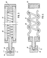
- FIG. 3 A modified version of a hose for filling liquid is shown in FIG. 3 in the liquid-filled state and in FIG. 4 in the empty state.
- FIG. 4 In these figures, only one hose 41 of the type of hoses 2 is shown in FIG. 1, but all hoses 2 according to FIG. 1 can be designed in this way.
- the hose 41 according to FIGS. 3 and 4 is sealed at one end by a stopper 42, the stopper 42 being able to be provided with a vent valve in the manner of the vent valve 3 in FIG. 2.
- the open end of the hose 41 is directly connected to a filling and emptying valve 43 in a sealing manner.
- the filling and emptying valve 43 can also be designed in the manner of the filling and emptying valve 6 in FIG. 1. In a first position, namely a filling position, the filling and emptying valve 43 connects the interior of the hose 41 via a first bore 44 to a source for a liquid under pressure. In the second position shown, the filling and emptying valve 43 is closed and the inside of the hose 41 is blocked off from the outside.
- the filling and emptying valve 43 connects the inside of the hose 41 via a second bore 45 to a conventional vacuum source, e.g. B. a suction pump, which serves to empty the hose 43; see. Fig. 4.
- a conventional vacuum source e.g. B. a suction pump, which serves to empty the hose 43; see. Fig. 4.
- An arrangement like the one above without the vibrating device 30 can be used in connection with a building material such as flow concrete, which does not require a vibrating effect during the hardening or hardening.
- the vibrating device 30 can also be omitted in the reusable formwork system according to FIG. 1 if flow concrete is used as the building material.
- the branch 5 can then be connected directly to the filling and emptying valve 6.
- the hose 41 is penetrated by a helical compression spring 46 of relatively large pitch over a substantial part of its length.
- the presence of the helical compression spring 46 not only prevents the hose 41 from kinking or constricting under load, but also prevents the hose 41 from kinking or constricting when it is not straight, but instead, e.g. B. to be laid in arches or around corners.
- the helical compression spring 46 expediently has an outer diameter in the range from 5% to 25%, ie. H. is a twentieth to a quarter of the inner diameter of the hose 41.
- the tube 41 collapses after emptying and under the action of the vacuum of the vacuum source, but is supported on the windings of the helical compression spring 46.
- the hose 41 detaches from the wall of the free space or cavity formed and is only in relatively loose contact with this wall in the area of the turns of the helical compression spring 46. In this way, the hose 41 or in the presence of helical compression springs 46 in the hoses 2 of the formwork system shown in FIG. 1, all hoses 2 can be removed practically effortlessly from the free spaces or cavities formed.
- FIG. 5 and 6 show a side view and a top view of a further filler 50, which can be used in connection with the filler 1 according to FIG. 1 of the reusable formwork system, in order to produce branches from the free spaces or cavities obtained by means of the filler 1.
- the further filler body 50 has a first end 51, which faces a hose 52 in the manner of the hose 2 in FIG. 1 or in the manner of the hose 41 in FIG. 3. From this end 51, a clamping device extends from two resilient, arc-shaped clamps 53, which lie opposite one another and between them define an opening 54 for receiving the hose 52. Each individual resilient bracket 53 extends beyond the central axis 55 of the hose 52 in such a way that the free ends 56 of the resilient brackets 53 have a distance which is smaller than the diameter of the hose 52 in the liquid-filled state.
- the resilient clips 53 have the shape of an arc of a circle, but they can also take any other shape that is suitable for achieving the releasable clamping connection with the liquid-filled hose 52.
- the further filling body 50 has a second end 57 facing away from the resilient clamps 53 with an outward, ie. H. in a region 58 widening away from the resilient clamps 53.
- the filling body 50 is of a generally conical or frustoconical shape.
- This area 58 is advantageously provided with a number of gradations 59, as a result of which the further filler 50 is better in the solidifying or hardening building material, e.g. B. Concrete sticks. 6, is a hollow body with an inner cavity 60.
- This cavity 60 there is an inwardly projecting step or shoulder 61 for the attack of a suitable tool with which the further filler 50 can be pulled out of the building material after solidification or hardening, leaving behind a further free space or cavity.
- This further free space or cavity forms a branch which starts from the free space or cavity which is formed by the associated hose 52 and extends to the surface of the component or component which has been formed from the building material.
- FIG. 7 shows a polygonal, in particular quadrangular design of the second end 57a or the outwardly widening region 58a of a further filler 50a, which can be used instead of the further filler 50 and at its first end (not shown) corresponding to the further filler 50 is formed.
- other fillers with other circumferential designs can be used where the circumstances require.
- the other fillers 50 and 50a form parts of the reusable formwork system and enable the formation of smooth branches which run from the free spaces or cavities mentioned at the beginning to the surface of the component.
- Such branches can be used to lay branches of electrical and other supply lines, but can also form branch ducts for ventilation and air extraction, for air heating or air cooling, for air conditioning and other things.
- Such branches can also be used to guide water, namely for irrigation or drainage. Extinguishing water channels for fire extinguishing systems can also be formed in this way.
Abstract
Description
Die Erfindung betrifft ein wiederverwendbares Schalungssystem zur Herstellung von Freiräumen in einem Baustoff, enthaltend mindestens einen an einem Ende geschlossenen und über ein Füll-und Entleerungsventil mit einer Flüssigkeit füllbaren Schlauch, der den Baustoff durchsetzt und den jeweils zu bildenden Freiraum bestimmt, wobei der Schlauch noch Verfestigung des Baustoffs unter Verbleiben des jeweligen Freiraums aus dem verfestigten Baustoff zur Wiederverwendung entfembar ist.The invention relates to a reusable formwork system for the production of free spaces in a building material, comprising at least one hose which is closed at one end and can be filled with a liquid via a filling and emptying valve, which penetrates the building material and determines the free space to be formed, the hose still Solidification of the building material while leaving the respective free space from the solidified building material can be removed for reuse.
Bei der Herstellung von Baukörpern, nämlich Teilen eines Gebaudes oder einzelnen Bauelementen, besteht das Bedürfnis, in die Baustoffe vor ihrer Verfestigung oder Härtung Freiräume oder Hohlräume, z. B. zur Leitungsverlegung einzuarbeiten. Dazu ist es beispielsweise bekannt, Kunststoffrohre in einem Baustoff wie Beton vor dessen Härtung zu verlegen. Das hat den Nachteil, daß solche Kunststoffrohre unlösbar mit dem Baukörper verbunden werden ; die Kunststoffrohre gehen damit verloren und sind einer Wiederverwendung nicht zugänglich.In the manufacture of structures, namely parts of a building or individual components, there is a need in the building materials before they solidify or harden free spaces or cavities, for. B. to incorporate for cable laying. For this purpose, it is known, for example, to lay plastic pipes in a building material such as concrete before it hardens. This has the disadvantage that such plastic pipes are permanently connected to the structure; the plastic pipes are lost and are not accessible for reuse.
Aus der deutschen Offenlegungsschrift Nr. 32 40 166 ist es bekannt, einen aufblasbaren Schlauch zur Schaffung von solchen Freiräumen oder Hohlräumen zu verwenden. Der Schlauch ist an einem Ende verschlossen und am anderen Ende an eine Druckmittelquelle, z. B. einen Preßlufterzeuger anschließbar. Der Schlauch wird verlegt und vor dem Aufbringen des Baustoffs auf einen vorgegebenen Innendruck aufgeblasen. Nach Aufbringen und Verfestigung des Baustoffs, sowie Ablassen des Innendrucks kann der Schlauch aus dem Baustoff entfernt werden und somit immer wieder verwendet werden.From German published patent application No. 32 40 166 it is known to use an inflatable tube to create such free spaces or cavities. The hose is closed at one end and at the other end to a pressure medium source, e.g. B. a compressed air generator can be connected. The hose is laid and inflated to a predetermined internal pressure before the building material is applied. After the building material has been applied and solidified, and the internal pressure has been released, the hose can be removed from the building material and thus used again and again.
Aus der FR-A-1 141 502 ist es bekannt, Hohlräume in Baustoffen durch einseitig geschlossene, flexible Hohlkörper zu formen, die in den Baustoff eingesetzt und über ein Füllventil mit Wasser oder Druckluft gefüllt werden. Die flexiblen Hohlkörper sind an ihrem geschlossen Ende mittig an ein Zugseil angeschlossen und können nach Verfestigung des Baustoffs durch Ziehen an dem Zugseil ausgeschalt werden.From FR-A-1 141 502 it is known to form cavities in building materials by flexible hollow bodies which are closed on one side and which are inserted into the building material and filled with water or compressed air via a filling valve. The flexible hollow bodies are connected in the middle to a pull rope at their closed end and can be removed by pulling on the pull rope after the building material has solidified.
Durch die FR-A-1 062 968 ist ein doppelwandiger Hohlkörper für den gleichen Zweck bekannt, der einen Außenkörper aus gummierter Leinwand und einen Innenkörper aus Weichgummi enthält. Der Innenkörper ist von einer Feder durchsetzt und wird mit Wasser gefüllt. Zur Entleerung wird der Zwischenraum zwischen dem Innenkörper und dem Außenkörper mit Druckluft beaufschlagt.FR-A-1 062 968 discloses a double-walled hollow body for the same purpose, which contains an outer body made of rubberized canvas and an inner body made of soft rubber. The inner body is penetrated by a spring and is filled with water. For emptying, the space between the inner body and the outer body is pressurized with compressed air.
Der Erfindung liegt die Aufgabe zugrunde, ein wiederverwendbares Schalungssystem der eingangs genannten Art zur Herstellung von Freiräumen in Baustoffen zu schaffen, das zur Herstellung unterschiedlich gestalteter Freiräume verwendet werden kann und universell einsetzbar ist, d. h. sowohl auf einer Baustelle, als auch bei der Vorfertigung von Bauteilen verwendet werden kann.The invention has for its object to provide a reusable formwork system of the type mentioned for the production of open spaces in building materials, which can be used to produce differently designed open spaces and is universally applicable, d. H. can be used on a construction site as well as in the prefabrication of components.
Der Erfindung liegt die weitere Aufgabe zugrunde, ein wiederverwendbares Schalungssystem der eingangs genannten Art zur Herstellung von Freiräumen in Baustoffen zu schaffen, durch das die Verfestigung des Baustoffs gefördert wird und das Freiräume mit besonders glatter Oberfläche liefert, ohne in seiner Wiederverwendbarkeit beeinträchtigt zu sein.The invention has the further object to provide a reusable formwork system of the type mentioned for the production of free spaces in building materials, by which the consolidation of the building material is promoted and which provides free spaces with a particularly smooth surface without being impaired in its reusability.
Erfindungsgemäß wird diese Aufgabe dadurch gelöst, daß der mindestens eine flüssigkeitsgefüllte Schlauch an seinem offenen Ende an eine Rüttelvorrichtung angeschlossen ist.According to the invention, this object is achieved in that the at least one liquid-filled hose is connected at its open end to a vibrating device.
Die Verwendung flüssigkeitsgefüllter Schläuche hat den Vorteil, daß durch die inkompressible Flüssigkeit ein auch nur örtlich begrenztes Zusammendrücken des Schlauches während der Verfestigung des Baustoffes wirksam verhindert wird. Durch die enge Anlage des sich verfestigenden Baustoffes an dem flüssigkeitsgefüllten Schlauch beziehungsweise den flüssigkeitsgefüllten Schläuchen wird eine besonders gleichmäßige und glatte Oberfläche des jeweils gebildeten Freiraums oder Hohlraums erhalten. Gleichzeitig ermöglicht aber die Flüssigkeitsfüllung, daß Rüttelschwingungen zur Verfestigung des Baustoffes durch Anregung von Schwingungen des flüssigkeitsgefüllten Schlauches erzeugt werden können.The use of liquid-filled hoses has the advantage that the incompressible liquid effectively prevents even locally restricted compression of the hose during the solidification of the building material. Due to the tight contact of the solidifying building material on the liquid-filled hose or the liquid-filled hoses, a particularly uniform and smooth surface of the free space or cavity formed is obtained. At the same time, however, the liquid filling enables vibrations to solidify the building material to be generated by exciting vibrations in the liquid-filled hose.
Vorteilhafterweise werden die Rüttelschwingungen durch einen hin- und hergehenden Kolben erzeugt, der unmittelbar auf die Flüssigkeit einwirkt, die in einem flüssigkeitsgefüllten Schlauch oder in einer Zuleitung enthalten ist, an die eine Vielzahl von Schläuchen parallel zueinander angeschlossen ist.The vibrations are advantageously generated by a reciprocating piston, which acts directly on the liquid contained in a liquid-filled hose or in a feed line to which a plurality of hoses are connected in parallel.
Um eine bessere Anpassung der Schläuche an vorgegebene Formen der Freiräume wie Bögen und dergleichen zu erreichen und die Gefahr von Abknickungen oder Einschnürungen sicher auszuschließen, ist es zweckmäßig, in den Schlauch eine Schraubendruckfeder einzulegen. Diese Schraubendruckfeder hat den weiteren wichtigen Vorteil, daß bei Anlegen eines Unterdrucks zur Entleerung der Schlauch nicht zusammenfällt, sondern von der Schraubendruckfeder abgestützt wird. Dadurch verringern sich die Anlageflächen zwischen dem verfestigten Baustoff und dem Schlauch ganz erheblich, so daß die Entfernung des Schlauches aus dem gebildeten Freiraum oder Hohlraum sehr erleichtert wird.In order to achieve a better adaptation of the hoses to predetermined shapes of the free spaces such as arches and the like and to reliably rule out the risk of kinks or constrictions, it is expedient to insert a helical compression spring into the hose. This helical compression spring has the further important advantage that when a vacuum is applied to empty the hose does not collapse but is supported by the helical compression spring. As a result, the contact surfaces between the solidified building material and the hose are reduced considerably, so that the removal of the hose from the free space or cavity formed is greatly facilitated.
Vorteilhafterweise ist der Schlauch an Stellen, an denen der Freiraum oder Hohlraum mit der Außenfläche des Baustoffs verbunden werden soll, mit einem weiteren Füllkörper versehen, der an einem Ende durch eine Klemmvorrichtung lösbar mit dem flüssigkeitsgefüllten Schlauch verbunden ist und nach Verfestigung des Baustoffs und Entfernung des flüssigkeitsgefüllten Schlauches abgezogen und wiederverwendet werden kann. Auf diese Weise wird ein weiterer Freiraum oder Hohlraum erhalten, der von dem durch den flüssigkeitsgefüllten Schlauch gebildeten Hohlraum abzweigt und in der Außenfläche oder Oberfläche des Baustoffs mündet.Advantageously, the hose is provided with a further filler at locations where the free space or cavity is to be connected to the outer surface of the building material is detachably connected at one end to the liquid-filled hose by a clamping device and can be removed and reused after the building material has solidified and the liquid-filled hose has been removed. In this way, a further free space or cavity is obtained which branches off from the cavity formed by the liquid-filled hose and opens into the outer surface or surface of the building material.
Die Verlegung der Schläuche in dem Baustoff kann bei armierten Baustoffen wie Beton dadurch erleichtert werden, daß der armierte Baustoff mit Abstandshalterungen bzw. Führungselementen für den Schlauch versehen wird. Dadurch wird sichergestellt, daß der Schlauch die jeweils gewünschte Lage einnimmt und diese Lage im flüssigkeitsgefüllten Zustand und während der Verfestigung des Baustoffs nicht verändert.The laying of the hoses in the building material can be facilitated in the case of reinforced building materials such as concrete in that the reinforced building material is provided with spacers or guide elements for the hose. This ensures that the hose assumes the desired position and does not change this position in the liquid-filled state and during the solidification of the building material.
Ausführungsbeispiele der Erfindung sind in den Abbildungen dargestellt und werden nachfolgend im einzelnen anhand der Bezugszeichen erläutert und beschrieben. Es zeigen
- Fig. 1 eine schematische, perspektivische Gesamtdarstellung eines Ausführungsbeispiels des erfindungsgemäßen wiederverwendbaren Schalungssystems für die Herstellung von Freiräumen in Verbindung mit einer Armierung für den Betonbau ;
- Fig. 1a eine andere Anordnung der Führungselemente für die flüssigkeitsgefüllten Schäuche in dem wiederverwendbaren Schalungssystem nach Fig. 1 ;
- Fig. 2 eine schematische Darstellung einer Rüttelvorrichtung bei dem wiederverwendbaren Schalungssystem nach Fig. 1 ;
- Fig. 3 eine modifizierte Ausführung eines Schlauches im flüssigkeitsgefüllten Zustand bei dem wiederverwendbaren Schalungssystem nach Fig. 1 ;
- Fig. 4 den Schlauch nach Fig. 3 im Leerzustand bei Anschluß an eine Unterdruckquelle ;
- Fig. 5 und 6 eine Seitenansicht bzw. Draufsicht auf einen weiteren Füllkörper zur Verwendung bei dem wiederverwendbaren Schalungssystem nach Fig. 1 ; und
- Fig. 7 eine Draufsicht auf eine modifizierte Ausführung des weiteren Füllkörpers nach Fig. 6.
- Figure 1 is a schematic, overall perspective view of an embodiment of the reusable formwork system according to the invention for the production of open spaces in connection with a reinforcement for concrete construction.
- 1a shows another arrangement of the guide elements for the liquid-filled hoses in the reusable formwork system according to FIG. 1;
- FIG. 2 shows a schematic illustration of a vibrating device in the reusable formwork system according to FIG. 1;
- 3 shows a modified version of a hose in the liquid-filled state in the reusable formwork system according to FIG. 1;
- 4 shows the hose according to FIG. 3 in the empty state when connected to a vacuum source;
- 5 and 6 are a side view and a top view of another filler body for use in the reusable formwork system according to FIG. 1; and
- 7 is a plan view of a modified embodiment of the further packing according to FIG. 6.
Das wiederverwendbare Schalungssystem zur Herstellung von Freiräumen oder Hohlräumen kann in unterschiedlichster Weise und in Verbindung mit den verschiedensten Baustoffen verwendet werden. Das in Fig. 1 schematisch in perspektivischer Ansicht gesamthaft dargestellte Ausführungsbeispiel des wiederverwendbaren Schalungssystems ist in Verbindung mit einer Armierung 10 für Beton als Baustoff abgebildet. Ein solches wiederverwendbares Schalungssystem wird z. B. bei der Herstellung einer Betondecke verwendet, die mit einer Reihe von im wesentlichen parallel zueinander durch die Betondecke verlaufenden Freiräumen oder Hohlräumen versehen werden soll.The reusable formwork system for the production of open spaces or cavities can be used in many different ways and in connection with a wide variety of building materials. The embodiment of the reusable formwork system shown schematically in overall perspective view in FIG. 1 is shown in connection with a
Kernstück des wiederverwendbaren Schalungssystems nach Fig. 1 ist ein Füllkörper 1, der aus einer Reihe im wesentlichen parallel verlaufender Schläuche 2 besteht, deren eine Enden jeweils durch ein Entlüftungsventil 3 entsprechend Fig. 2 verschlossen sind und deren offene Enden an eine gemeinsame Zuleitung 4 angeschlossen sind. Die gemeinsame Zuleitung 4 ist über eine Abzweigung 5 an ein Füll- und Entleerventil 6 üblicher Bauart und an eine weiter unten im Zusammenhang mit Fig. 2 beschriebene Rüttelvorrichtung 30 angeschlossen. Die gemeinsame Zuleitung 4 ist weiterhin mit einem Sicherheits- bzw. Uberdruck-Entlastungsventil 7 versehen, das den Füllkörper 1 selbsttätig von einem unzulässig erhöhten Innendruck entlastet.The core of the reusable formwork system according to FIG. 1 is a packing 1, which consists of a series of essentially
Der Füllkörper 1 bzw. die Schläuche 2 sind in eine Verschalung 8 üblicher Bauart für Beton eingelegt, und diese Verschalung 8 ist daher nicht im einzelnen dargestellt. Der Füllkörper 1 bzw. die Schläuche 2 bestehen aus Gummi oder Kunststoff oder einem anderen mit Beton verträglichen Material, das eine gegenüber den auftretenden Innendrücken ausreichende Druckfestigkeit besitzt, jedoch flexibel ist, um Verformungen folgen zu können. In besonderen Fällen kann der Füllkörper auch in konventioneller Weise mit einer perforierten Folie überzogen werden, die bei Entfernung des Füllkörpers 1 an dem verfestigten oder gehärteten Baustoff haften bleibt.The filler 1 or the
In dem dargestellten Ausführungsbeispiel ist die Armierung 10 für eine Betondecke vorgesehen. Diese Armierung 10 besteht aus einer ersten, nämlich unteren Baustahlmatte 11 und einer zweiten, nämlich oberen Baustahlmatte 12, die im Abstand zueinander im wesentlichen parallel verlaufend angeordnet sind und durch Abstandshalter bzw. Führungselemente 13 im Abstand voneinander gehalten werden. Die Abstandshalter bilden dabei Führungselemente 13 für die Schläuche 2, die entweder durch die Führungselemente 13 hindurch oder zwischen benachbarten Führungselementen 13 verlaufen, wobei die Führungselemente 13 verschiedenen Reihen 14 von hintereinander angeordneten Führungselementen 13 bilden. Die Abstandshalter bzw. Führungselemente 13 stellen sicher, daß die Schläuche 2 in der gewünschten Weise verlaufen und ihre Anordnung während der Verfestigung oder Härtung des Betons praktisch nicht ändern.In the illustrated embodiment, the
Die Abstandshalter bzw. Führungselemente 13 sind aus federndem Material, insbesondere Armierungsstahl derart gestaltet, daß sie in besonders einfacher Weise montiert werden können. In dem dargestellten Ausführungsbeispiel besteht jedes Führungselement 13 aus zwei Winkelementen 15 und einem dazwischen angeordneten oder mittigen Winkelelement, das als Rastelement 16 ausgebildet ist. Abhängig von den Gegebenheiten und Anforderungen des jeweiligen Anwendungszwecks kann aber auch ein anderes Zahlenverhältnis zwischen den Winkelementen 15 und den Rastelementen 16 gewählt werden.The spacers or guide
Die Winkelelemente 15 und das Rastelement 16 schließen im wesentlichen einen gleichen Winkel ein, der an den jeweiligen Anwendungsfall bzw. die jeweils vorhandenen Abstände in der Baustahlmatte 11 angepaßt ist. Im einzelnen ist dabei das Rastelement 16 so ausgebildet, daß es an zwei benachbarten Elementen 11 a und 11 b der Baustahlmatte 11 einrastet. Die Winkelemente 15 und das Rastelement 16 sind an ihren Spitzen durch eine Strebe in Form eines Stahlstabes 17 und nahe ihren freien Enden durch Streben in Form von Stahlstäben 18 miteinander verbunden.The
Die freien Enden der Winkelelemente 15 sind jeweils mit einer Schutzvorrichtung versehen, die in dem dargestellten Ausführungsbeispiel aus Kunststoffteilen 15a bestehen. Die freien Enden der Winkelelemente 15 stehen mit den Kunststoffteilen 15a auf der Verschalung 8 auf. Dabei verhindern die Kunststoffteile 15a nicht nur das Eindringen der freien Enden der Winkelelemente 15 in die meist aus Holz bestehende Verschalung 8, sondern verhindern darüber hinaus die Korrosion der Winkelelemente 15 an den vorstehenden freien Enden.The free ends of the
Das Rastelement 16 ist an seinen freien Enden mit jeweils einem Rastteil 16a versehen, das die einrastende Verbindung zwischen dem Abstandshalter bzw. dem Führungselement 13 und der ersten Baustahlmatte 11 herstellt. In dem dargestellten Ausführungsbeispiel sind die Rastteile 16a aus hakenförmig umgebogenen freien Enden des Rastteils 16 gebildet. In einer anderen Ausführung können die Rastteile 16a auch von abgewinkelten Rastteilen des Rastelementes 16 gebildet werden. Darin sind die freien Enden so abgewinkelt, daß sie nach Einrastung an den benachbarten Elementen 11 a und 11 b der ersten Baustahlmatte 11 nicht parallel zu dieser Baustahlmatte 11 verlaufen, sondern unter einem zu dieser Baustahlmatte 11 gerichteten Winkel.The latching
Zur Montage werden die Abstandshalter bzw. Führungselemente 13 zusammengedrückt, so daß die freien Enden der Rastelemente 16 mit den Rastteilen 16a zwischen den benachbarten Elementen 11 a und 11 der ersten Baustahlmatte 11 hindurchgeführt werden ; die Kunststoffteile 15a der Winkelelemente 15 stehen dann auf der Verschalung 8 auf. Beim Loslassen greifen die Rastteile 16a des Rastelementes 16 unter die benachbarten Elemente 11 a und 11b der ersten Baustahlmatte 11. Durch die Umbiegung der freien Enden des Rastelementes 16 zu den Rastteilen 16a befinden sich diese Rastteile 16a auf einer Ebene oberhalb der Verschalung 8, so daß die erste Baustahlmatte 11 nach Anbringung der Abstandshalter bzw. Führungselemente 13 von der Verschalung 8 abgehoben wird. Die Ausbildung der Rastteile 16a stellt sicher, daß die Abstandshalter bzw. Führungselemente 13 bei Belastung der Armierung 10 auf der Seite der zweiten Baustahlmatte 12 sicher mit der ersten Baustahlmatte 11 verbunden bleiben, denn die dabei erfolgende Spreizung der Rastelemente 16 führt nicht zu einer Trennung der Rastteile 16a von den zugehörigen Elementen 11 a und 11 b der ersten Baustahlmatte 11.For assembly, the spacers or guide
Im eingebauten Zustand der Abstandshalter bzw. Führungselemente 13 befindet sich jedes der benachbarten Elemente 11a und 11 b der Baustahlmatte 11 zwischen dem zugehörigen Rastteil 16a des Rastelementes 16 und dem zugehörigen Stahlstab 18, der die Winkelelemente 15 und das Rastelement 16 nahe deren freien Enden miteinander verbindet.In the installed state of the spacers or guide
Zur zusätzlichen Verstärkung können die Abstandshalter bzw. Führungselemente 13 weitere Stahlstäbe 19 aufweisen, welche die benachbarten Winkelelemente 15 jedes Abstandselementes 13 entweder seitlich bzw. diagonal im Bereich zwischen der Spitze und den freien Enden miteinander verbinden. Die zweite Baustahlmatte 12 kann in üblicher Weise mit den Spitzen der Abstandshalter bzw. Führungselementen 13 verbunden werden.For additional reinforcement, the spacers or guide
Fig. 1a zeigt eine andere Anordnung der Abstandshalter bzw. Führungselemente 13, bei der benachbarte Rastelemente 16 über ihre hakenförmig umgebogenen Rastteile 16a miteinander und mit gemeinsamen Armierungsstäben 20 einer Armierung verbunden sind, die beispielweise vertikal in einer Säule oder dergleichen verläuft.1 a shows another arrangement of the spacers or guide
Die Rüttelvorrichtung 30 und ihre Verbindung mit dem offenen Ende 31 eines einzelnen Schlauches nach Art des Schlauches 2 sind schematisch in Fig. 2 dargestellt. Die Rüttelvorrichtung kann in entsprechender Weise, siehe Fig. 1, auch an die Abzweigung 5 der gemeinsamen Zuleitung 4 zu den Schläuchen 2 angeschlossen sein. Das offene Ende 31 ist abdichtend mit einem Zylinder 32 verbunden, in dem ein Kolben 33 abdichtend hin-und herbeweglich geführt ist. Der Kolben 33 steht über eine Übersetzung 34 mit einem Antriebsmotor 35 in Antriebsverbindung. Der Antriebsmotor 35 kann beispielsweise ein Elektromotor oder auch ein Verbrennungsmotor sein und ist in seiner Drehzahl vorzugsweise stufenlos veränderlich. Die Übersetzung 34 enthält einen Exzenter E, über den der Hubweg des Kolbens 33 vorzugsweise stufenlos einstellbar ist.The vibrating
Durch den Antriebsmotor 35 wird der Kolben 33 in dem Zylinder 32 mit einer Frequenz hin- und herbewegt, die durch die jeweils am Antriebsmotor 35 eingestellte Drehzahl gegeben ist, während der Hub des Kolbens 33 an dem Exzenter E eingestellt wird. Wenn die Zuleitung 4 und die damit parallel verbundenen Schläuche 2 mit einer Flüssigkeit, z. B. Wasser gefüllt sind, werden somit durch die Bewegung des Kolbens 33 im Zylinder 32 Schwingungen hervorgerufen, die sich als Rüttelschwingungen in dem die Schläuche 2 umgebenden Beton auswirken und dessen Verfestigung bzw. Durchhärtung begünstigen. Durch die stufenlose Einstellung des Kolbenhubs und der Drehzahl des Antriebsmotors 35 können die Rüttelschwingungen ohne weiteres an die jeweils günstigsten Arbeitsbedingungen angepaßt werden. Durch entsprechende Einstellung wird dabei das Auftreten von Resonanz- oder Eigenschwingungen vermieden. Ein kombiniertes Druck-Frequenz-Anzeigegerät F zeigt dabei die bei den Rüttelschwingungen auftretenden Drücke und Frequenzen an.The
Das vorstehend beschriebene wiederverwendbare Schalungssystem arbeitet wie folgt :The reusable formwork system described above works as follows:
Nach Verlegung der Armierung 10 werden die mit der gemeinsamen Zuleitung 4 verbundenen Schläuche 2 innerhalb der einzelnen Abstandshalter bzw. Führungselemente 13 bzw. zwischen den benachbarten Abstandshaltern bzw. Führungselementen 13 verlegt. Die Abzweigung 5 wird mit ihrem offenen Ende an den Zylinder 32 der Rüttelvorrichtung 30 abdichtend angeschlossen. Anschließend wird die gesamte Anlage über das Füll- und Entleerventil 6 mit einer Flüssigkeit, z. B. Wasser gefüllt, wobei durch die Entlüftungsventile 3 sichergestellt wird, daß die Anlage vor Inbetriebnahme völlig entlüftet ist. Nach Aufbringen des Betons wird die Rüttelvorrichtung 30 betätigt, wobei die Rüttelvorrichtung 30 so rasch auf die voreingestellte Hubfrequenz des Kolbens 33 hochgefahren wird, daß der ober die Bereiche kritischer Eigenschwingungen rasch und ohne schädliche Nebenwirkungen durchfahren werden.After the
Nach der vorgegebenen Rüttelzeit, die beispielsweise durch die Art des Betons und durch die Art und Verlegung der Armierung 10 bestimmt ist, wird die Rüttelvorrichtung 30 abgeschaltet und die Anlage nach Öffnen der Entlüftungsventile 3 über das Füll- und Entleerventil 6 entleert. Danach können die Schläuche 2 ohne weiteres aus dem verfestigten bzw. gehärteten Beton entfernt werden und stehen dann zur Wiederverwendung zur Verfügung. Dabei hat sich herausgestellt, daß die Schläuche 2 jederzeit ohne Schwierigkeit aus den gebildeten Freiräumen oder Hohlräumen herausgezogen werden können ; insbesondere sind die Wände der gebildeten Freiräume oder Hohlräume gleichmäßig oder glatt ausgebildet, so daß solche Freiräume oder Hohlräume als Durchgangsrohre nicht nur für z. B. elektrische oder andere Versorgungsleitungen, sondern bei Zusatz entsprechender Zuschläge, die den Beton wasserdicht machen, auch unmittelbar als Wasserkanäle geeignet sind. Solche Freiräume bzw. Hohlräume können in Betondecken wie Betonwänden in gleicher Weise ausgebildet werden.After the specified vibrating time, which is determined, for example, by the type of concrete and the type and laying of the
Das vorstehende Ausführungsbeispiel des wiederverwendbaren Schalungssystems ist im Zusammenhang mit der Herstellung von einer Betondecke mit Freiräumen oder Hohlräumen beschrieben worden. Ein solches wiederverwendbares Schalungssystem kann in gleicher Weise und mit gleichen Vorteilen zur Herstellung von Freiräumen oder Hohlräumen in Betonwänden und anderen Betonbauteilen verwendet werden. Es läßt sich mit gleichem Erfolg auch im Zusammenhang mit anderen Baustoffen, die sich verfestigen oder härten, verwenden, sofern dabei keine Bindung zwischen dem Baustoff und dem Schlauch bzw. den Schläuchen eintritt, was durch Wahl des entsprechenden Schlauchmaterials sichergestellt werden kann. In gleicher Weise und mit gleichem Erfolg kann das wiederverwendbare Schalungssystem auch bei der Vorfertigung von Bauelementen aus Beton oder anderen härtenden oder sich verfestigenden Baustoffen eingesetzt werden. Es können so insgesamt in sehr einfacher Weise und unter Einsparung sonst anfallender erheblicher Kosten für Leitungsrohre auch Belüftungs- und Entlüftungskanäle bzw. Erwärmungs- und Abkühlungskanäle erhalten werden, insbesondere bei Verwendung von wasserdichtem Beton oder dergleichen auch wasserführende Kanäle. Das wiederverwendbare Schalungssystem kann mit großem Vorteil gerade bei großflächigen Bauten oder vorgefertigten Bauteilen eingesetzt werden, bei denen Schlauchleitungen bis zu ca. 100 m erfolgreich eingesetzt werden können.The above exemplary embodiment of the reusable formwork system has been described in connection with the production of a concrete ceiling with free spaces or cavities. Such a reusable formwork system can be used in the same way and with the same advantages for the production of open spaces or cavities in concrete walls and other concrete components. It can be used with the same success in connection with other building materials that solidify or harden, provided that there is no bond between the building material and the hose or hoses, which can be ensured by choosing the appropriate hose material. In the same way and with the same success, the reusable formwork system can also be used in the prefabrication of components made of concrete or other hardening or solidifying building materials. Overall, ventilation and ventilation ducts or heating and cooling ducts can also be obtained in a very simple manner and with the saving of considerable costs for line pipes, especially when using waterproof concrete or the like, and water-conducting ducts. The reusable formwork system can be used to great advantage especially in large-scale buildings or prefabricated components in which hose lines up to approx. 100 m can be used successfully.
Eine modifizierte Ausführung eines Schlauches zur Flüssigkeitsfüllung ist in Fig. 3 in flüssigkeitsgefülltem Zustand und in Fig. 4 in entleertem Zustand dargestellt. In diesen Abbildungen ist nur ein Schlauch 41 nach Art der Schläuche 2 in Fig. 1 dargestellt, jedoch können alle Schläuche 2 gemäß Fig. 1 in dieser Weise ausgebildet werden.A modified version of a hose for filling liquid is shown in FIG. 3 in the liquid-filled state and in FIG. 4 in the empty state. In these figures, only one
Der Schlauch 41 nach Fig. 3 und 4 ist an einem Ende durch einen Stopfen 42 abdichtend verschlossen, wobei der Stopfen 42 mit einem Entlüftungsventil nach Art des Entlüftungsventils 3 in Fig. 2 versehen werden kann. Das offene Ende des Schlauches 41 ist bei dieser Ausführung unmittelbar mit einem Füll- und Entleerventil 43 abdichtend verbunden. Das Füll- und Entleerventil 43 kann aber auch nach Art des Füll- und Entleerventils 6 in Fig. 1 ausgebildet sein. Das Füll- und Entleerventil 43 verbindet in einer ersten Stellung, nämlich einer Füllstellung, das Innere des Schlauches 41 über eine erste Bohrung 44 mit einer Quelle für eine unter Druck stehende Flüssigkeit. In der dargestellten zweiten Stellung ist das Füll-und Entleerventil 43 geschlossen und das Innere des Schlauches 41 nach außen abgesperrt. In einer dritten Stellung, nämlich einer Entleerstellung, verbindet das Füll- und Entleerventil 43 das Innere des Schlauches 41 über eine zweite Bohrung 45 mit einer konventionellen Unterdruckquelle, z. B. einer Saugpumpe, die zum Entleeren des Schlauches 43 dient; vgl. Fig. 4. Eine Anordnung wie die vorstehende ohne die Rüttelvorrichtung 30 kann in Verbindung mit einem Baustoff wie Fließbeton verwendet werden, der keine Rüttelwirkung bei der Verfestigung oder Härtung benötigt. Ebenso kann auch bei dem wiederverwendbaren Schalungssystem nach Fig. 1 die Rüttelvorrichtung 30 entfallen, wenn Fließbeton als Baustoff verwendet wird. Die Abzweigung 5 kann dann direkt an das Füll- und Entleerventil 6 angeschlossen werden.The
Der Schlauch 41 wird über einen wesentlichen Teil seiner Länge von einer Schraubendruckfeder 46 relativ großer Ganghöhe durchsetzt. Die Anwesenheit der Schraubendruckfeder 46 verhindert nicht nur ein Abknicken oder Einschnüren des Schlauches 41 bei Belastung, sondern verhindert auch ein Abknicken oder Einschnüren des Schlauches 41, wenn dieser nicht geradlinig, sondern z. B. in Bogen oder um Ecken verlegt werden soll.The
Die Schraubendruckfeder 46 hat zweckmäßigerweise einen Außendurchmesser der im Bereich von 5 % bis zu 25 %, d. h. ein Zwanzigstel bis ein Viertel des Innendurchmessers des Schlauches 41 beträgt. Wie in Fig. 4 im einzelnen dargestellt ist, fällt der Schlauch 41 nach Entleerung und unter der Wirkung des Unterdrucks der Unterdruckquelle zusammen, wird aber an den Windungen der Schraubendruckfeder 46 abgestützt. Dabei löst sich der Schlauch 41 von der Wandung des gebildeten Freiraums oder Hohlraums ab und steht nur noch im Bereich der Windungen der Schraubendruckfeder 46 mit dieser Wandung in relativ losem Kontakt. Auf diese Weise läßt sich der Schlauch 41 bzw. lassen sich bei Anwesenheit von Schraubendruckfedem 46 in den Schläuchen 2 des in Fig. 1 dargestellten Schalungssystems alle Schläuche 2 praktisch mühelos aus den gebildeten Freiräumen oder Hohlräumen entfernen.The
Fig. 5 und 6 zeigen eine Seitenansicht bzw. eine Draufsicht auf einen weiteren Füllkörper 50, der in Verbindung mit dem Füllkörper 1 nach Fig. 1 des wiederverwendbaren Schalungssystems verwendet werden kann, um Abzweigungen von den mittels des Füllkörpers 1 erhaltenen Freiräumen oder Hohlräumen herzustellen.5 and 6 show a side view and a top view of a
Der weitere Füllkörper 50 besitzt ein erstes Ende 51, das jeweils einem Schlauch 52 nach Art des Schlauches 2 in Fig. 1 oder nach Art des Schlauches 41 in Fig. 3 zugekehrt ist. Von diesem Ende 51 erstreckt sich eine Klemmvorrichtung aus zwei federnden, bogenförmigen Klammern 53, die einander gegenüberliegen und zwischen sich eine Öffnung 54 zur Aufnahme des Schlauches 52 bestimmen. Jede einzelne federnde Klammer 53 erstreckt sich dabei über die Mittelachse 55 des Schlauches 52 hinaus in der Weise, daß die freien Enden 56 der federnden Klammern 53 einen Abstand haben, der kleiner ist als der Durchmesser des Schlauches 52 im flüssigkeitsgefüllten Zustand. In dem dargestellten Ausführungsbeispiel besitzen die federnden Klammern 53 die Form eines Kreisbogens, jedoch können sie auch jede andere Form annehmen, die zur Erzielung der lösbaren Klemmverbindung mit dem flüssigkeitsgefüllten Schlauch 52 geeignet ist.The
Der weitere Füllkörper 50 besitzt ein den federnden Klammern 53 abgewandtes zweites Ende 57 mit einem sich nach außen, d. h. in einer von den federnden Klammern 53 wegweisenden Richtung erweiternden Bereich 58. In diesem Bereich 58 ist der Füllkörper 50 von allgemein kegelförmiger oder kegelstumpfförmiger Gestalt. Vorteilhafterweise ist dieser Bereich 58 mit einer Anzahl von Abstufungen 59 versehen, wodurch der weitere Füllkörper 50 besser in dem sich verfestigenden oder härtenden Baustoff, z. B. Beton haftet. Der weitere Füllkörper 50 ist, wie sich insbesondere aus Fig. 6 ergibt, ein Hohlkörper mit einem inneren Hohlraum 60. In diesem Hohlraum 60 befindet sich eine nach innen vorspringende Stufe oder Schulter 61 für den Angriff eines geeigneten Werkzeuges, mit dem der weitere Füllkörper 50 nach Verfestigung oder Härtung unter Hinterlassung eines weiteren Freiraums oder Hohlraums aus dem Baustoff herausgezogen werden kann. Dieser weitere Freiraum oder Hohlraum bildet eine Abzweigung, die von dem Freiraum oder Hohlraum ausgeht, der durch den zugehörigen Schlauch 52 gebildet wird, und sich bis zur Oberfläche des Bauteils oder Bauelements erstreckt, das aus dem Baustoff gebildet worden ist.The
In Fig. 7 ist eine mehreckige, insbesondere viereckige Ausbildung des zweiten Endes 57a bzw. des sich nach außen erweiternden Bereiches 58a eines weiteren Füllkörpers 50a gezeigt, der anstelle des weiteren Füllkörpers 50 verwendet werden kann und an seinem nicht dargestellten ersten Ende entsprechend dem weiteren Füllkörper 50 ausgebildet ist. Im gleicher Weise können auch weitere Füllkörper mit anderen Umfangsgestaltungen Verwendung finden, wo dies die jeweiligen Umstände erfordern.7 shows a polygonal, in particular quadrangular design of the second end 57a or the outwardly widening region 58a of a
Die weiteren Füllkörper 50 und 50a bilden Teile des wiederverwendbaren Schalungssystems und ermöglichen die Ausformung von glatten Abzweigungen, die von den eingangs erwähnten Freiräumen oder Hohlräumen zur Oberfläche des Bauteils oder Bauelementes verlaufen. Solche Abzweigungen können zur Verlegung von Abzweigungen elektrischer und anderer Versorgungsleitungen dienen, aber auch Abzweigkanäle für Be-und Entlüftungen, für Luftheizungen oder Luftkühlungen, für Klimatisierungen und anderes mehr bilden. Bei Verwendung von wasserdichtem Baustoff oder Beton können solche Abzweigungen auch zur Wasserführung dienen, nämlich zur Bewässerung oder auch zur Entwässerung. Auf diese Weise lassen sich auch Löschwasserkanäle für Feuerlöschanlagen ausbilden.The
Claims (28)
Priority Applications (1)
| Application Number | Priority Date | Filing Date | Title |
|---|---|---|---|
| AT86902361T ATE43878T1 (en) | 1985-03-09 | 1986-03-07 | REUSABLE FORMWORK SYSTEM FOR CREATING OPEN SPACES IN BUILDING MATERIALS. |
Applications Claiming Priority (8)
| Application Number | Priority Date | Filing Date | Title |
|---|---|---|---|
| DE19853508444 DE3508444A1 (en) | 1985-03-09 | 1985-03-09 | Device for producing cavities for installations |
| DE3508444 | 1985-03-09 | ||
| DEU0850699 | 1985-03-11 | ||
| DE8506996U DE8506996U1 (en) | 1985-03-11 | 1985-03-11 | Component - spacer with snap-in device in reinforcement construction (made of steel) |
| DE3509873 | 1985-03-19 | ||
| DE19853509873 DE3509873A1 (en) | 1985-03-19 | 1985-03-19 | Shuttering device for producing openings |
| DE19853509994 DE3509994A1 (en) | 1985-03-20 | 1985-03-20 | Vibratory technique with liquid frequency generator |
| DE3509994 | 1985-03-20 |
Publications (2)
| Publication Number | Publication Date |
|---|---|
| EP0248813A1 EP0248813A1 (en) | 1987-12-16 |
| EP0248813B1 true EP0248813B1 (en) | 1989-06-07 |
Family
ID=27433314
Family Applications (1)
| Application Number | Title | Priority Date | Filing Date |
|---|---|---|---|
| EP86902361A Expired EP0248813B1 (en) | 1985-03-09 | 1986-03-07 | Re-usable casing system for the creation of free spaces in building materials |
Country Status (9)
| Country | Link |
|---|---|
| EP (1) | EP0248813B1 (en) |
| AT (1) | ATE43878T1 (en) |
| AU (1) | AU590266B2 (en) |
| DE (1) | DE3663831D1 (en) |
| DK (1) | DK532386A (en) |
| ES (1) | ES8800391A1 (en) |
| FI (1) | FI873870A (en) |
| NO (1) | NO864466D0 (en) |
| WO (1) | WO1986005229A1 (en) |
Families Citing this family (5)
| Publication number | Priority date | Publication date | Assignee | Title |
|---|---|---|---|---|
| DE4223844A1 (en) * | 1992-07-20 | 1994-01-27 | Rene P Schmid | Device and method for injecting injection material into concrete joint systems |
| FI4705U1 (en) * | 2000-06-15 | 2000-11-23 | Juhani Kauko | Support for mounting of thermal insulation |
| FI20022292A0 (en) * | 2002-12-31 | 2002-12-31 | Joutsenon Elementti Oy | The mounting device |
| DE102019123880A1 (en) * | 2019-09-05 | 2021-03-11 | Peri Gmbh | Textile formwork element |
| CN116677205B (en) * | 2023-03-13 | 2024-01-23 | 扬州中建建设机械有限公司 | Concrete pouring device for building construction |
Family Cites Families (7)
| Publication number | Priority date | Publication date | Assignee | Title |
|---|---|---|---|---|
| FR805636A (en) * | 1935-08-14 | 1936-11-25 | T U J O Sa | Process for the construction of floors and resulting floors |
| FR1062968A (en) * | 1952-09-02 | 1954-04-28 | Improvements to the production processes for monolithic pipes and pipes obtained by this process | |
| FR1141502A (en) * | 1955-12-09 | 1957-09-03 | Process intended to lighten large-sized materials by the use of "pockets to make hollows" with progressive release; the use of <<hinks>> for utility purposes; the manufacture and use of the products obtained | |
| GB963253A (en) * | 1960-04-29 | 1964-07-08 | Cufflin Holdings Ltd | Improvements in inflatable tubular formers |
| CH426981A (en) * | 1965-01-25 | 1966-12-31 | Bassani Spa | Equipment for the formation, by means of hollow organs and pipes that remain caught in the casting, of recesses for electrical installations in prefabricated elements for building constructions |
| US3898778A (en) * | 1974-01-10 | 1975-08-12 | Lennart G Erickson | Slotted drainage conduit and integral concrete floor |
| DE3240166A1 (en) * | 1982-10-29 | 1984-05-03 | Andreas 4441 Spelle Holterhus | Device for producing free spaces for installations |
-
1986
- 1986-03-07 AT AT86902361T patent/ATE43878T1/en active
- 1986-03-07 AU AU56640/86A patent/AU590266B2/en not_active Ceased
- 1986-03-07 EP EP86902361A patent/EP0248813B1/en not_active Expired
- 1986-03-07 DE DE8686902361T patent/DE3663831D1/en not_active Expired
- 1986-03-07 WO PCT/EP1986/000122 patent/WO1986005229A1/en active IP Right Grant
- 1986-03-08 ES ES552807A patent/ES8800391A1/en not_active Expired
- 1986-11-07 NO NO864466A patent/NO864466D0/en unknown
- 1986-11-07 DK DK532386A patent/DK532386A/en not_active Application Discontinuation
-
1987
- 1987-09-08 FI FI873870A patent/FI873870A/en not_active IP Right Cessation
Also Published As
| Publication number | Publication date |
|---|---|
| DE3663831D1 (en) | 1989-07-13 |
| AU590266B2 (en) | 1989-11-02 |
| NO864466L (en) | 1986-11-07 |
| ATE43878T1 (en) | 1989-06-15 |
| DK532386D0 (en) | 1986-11-07 |
| FI873870A0 (en) | 1987-09-08 |
| ES552807A0 (en) | 1987-11-01 |
| NO864466D0 (en) | 1986-11-07 |
| FI873870A (en) | 1987-09-08 |
| WO1986005229A1 (en) | 1986-09-12 |
| ES8800391A1 (en) | 1987-11-01 |
| AU5664086A (en) | 1986-09-24 |
| DK532386A (en) | 1986-11-07 |
| EP0248813A1 (en) | 1987-12-16 |
Similar Documents
| Publication | Publication Date | Title |
|---|---|---|
| DE3016601C2 (en) | Device for erecting a support column in an underground mine | |
| DE2629214A1 (en) | METHOD AND MEANS OF LINING PIPELINE | |
| DE2847906A1 (en) | METHOD AND SYSTEM FOR SUPPORTING A FIRST, IN PARTICULAR A FIRST, OF A SUBSIDIARY EXCAVATION | |
| DE2201319B2 (en) | METHOD AND DEVICE FOR MANUFACTURING A FOAMED BOAT SHELL FOR A SAILBOAT | |
| DE1559044B1 (en) | Face formwork for individual concrete wall sections with a holding device for a joint sealing plate | |
| DE2125173C3 (en) | Device for producing a support element, in particular for use in underground mining operations | |
| DE3504829A1 (en) | THREADED ELEMENT | |
| EP0059171A1 (en) | Dowel and sleeve for the absorption and transfer of a shearing force | |
| EP0248813B1 (en) | Re-usable casing system for the creation of free spaces in building materials | |
| DE69733691T2 (en) | STRUCTURE AND METHOD OF TISSUEING PIPES | |
| DE102011075463A1 (en) | Wall has integrated formwork of two opposite and parallel walls, where space is defined between them, and walls are connected by metal reinforcement | |
| EP0292765B1 (en) | Method for welding impervious membranes in underground walls | |
| DE2111730A1 (en) | Component for building walls | |
| DE6607126U (en) | PIPE FOR SEMI-FLEXIBLE HOLLOW PIPES | |
| CH658492A5 (en) | CONTAINER MADE OF PRE-PREPARED CONCRETE ELEMENTS AND THEIR PRODUCTION. | |
| DE3114744A1 (en) | Formwork for concrete foundations | |
| DE3340810A1 (en) | Process for producing prismatic components of reinforced concrete, in particular reinforced concrete supports, and an apparatus for carrying out the process | |
| DE3718436A1 (en) | Process for producing tower-like structures | |
| WO1984000189A1 (en) | Method for wall concreting and formwork to implement such method | |
| DE2221653A1 (en) | Reusable hollow formwork, as well as procedures for its operation | |
| DE2658967A1 (en) | Underground liquid storage tank - with casing of concrete or synthetic resin concrete with external skin formed of glass fibre laminate | |
| WO2017133987A1 (en) | Method and system for the bottom-side separation of a body to be worked out of a rock | |
| AT300284B (en) | Method for erecting a shell-shaped building structure | |
| AT225889B (en) | Process for the creation of a reinforced concrete structure and structure created according to this process | |
| AT156911B (en) | Process and device for the production of castings made of concrete or reinforced concrete and. Like., In particular of masts, posts, columns, tubes, etc. |
Legal Events
| Date | Code | Title | Description |
|---|---|---|---|
| PUAI | Public reference made under article 153(3) epc to a published international application that has entered the european phase |
Free format text: ORIGINAL CODE: 0009012 |
|
| 17P | Request for examination filed |
Effective date: 19870901 |
|
| AK | Designated contracting states |
Kind code of ref document: A1 Designated state(s): AT BE CH DE FR GB IT LI LU NL SE |
|
| 17Q | First examination report despatched |
Effective date: 19881003 |
|
| GRAA | (expected) grant |
Free format text: ORIGINAL CODE: 0009210 |
|
| AK | Designated contracting states |
Kind code of ref document: B1 Designated state(s): AT BE CH DE FR GB IT LI LU NL SE |
|
| PG25 | Lapsed in a contracting state [announced via postgrant information from national office to epo] |
Ref country code: IT Free format text: LAPSE BECAUSE OF FAILURE TO SUBMIT A TRANSLATION OF THE DESCRIPTION OR TO PAY THE FEE WITHIN THE PRE;WARNING: LAPSES OF ITALIAN PATENTS WITH EFFECTIVE DATE BEFORE 2007 MAY HAVE OCCURRED AT ANY TIME BEFORE 2007. THE CORRECT EFFECTIVE DATE MAY BE DIFFERENT FROM THE ONE RECORDED.SCRIBED TIME-LIMIT Effective date: 19890607 Ref country code: FR Free format text: THE PATENT HAS BEEN ANNULLED BY A DECISION OF A NATIONAL AUTHORITY Effective date: 19890607 Ref country code: SE Effective date: 19890607 Ref country code: GB Effective date: 19890607 Ref country code: NL Effective date: 19890607 Ref country code: BE Effective date: 19890607 |
|
| REF | Corresponds to: |
Ref document number: 43878 Country of ref document: AT Date of ref document: 19890615 Kind code of ref document: T |
|
| REF | Corresponds to: |
Ref document number: 3663831 Country of ref document: DE Date of ref document: 19890713 |
|
| EN | Fr: translation not filed | ||
| NLV1 | Nl: lapsed or annulled due to failure to fulfill the requirements of art. 29p and 29m of the patents act | ||
| GBV | Gb: ep patent (uk) treated as always having been void in accordance with gb section 77(7)/1977 [no translation filed] | ||
| PG25 | Lapsed in a contracting state [announced via postgrant information from national office to epo] |
Ref country code: AT Effective date: 19900307 |
|
| PG25 | Lapsed in a contracting state [announced via postgrant information from national office to epo] |
Ref country code: LI Effective date: 19900331 Ref country code: LU Free format text: LAPSE BECAUSE OF NON-PAYMENT OF DUE FEES Effective date: 19900331 Ref country code: CH Effective date: 19900331 |
|
| PLBE | No opposition filed within time limit |
Free format text: ORIGINAL CODE: 0009261 |
|
| STAA | Information on the status of an ep patent application or granted ep patent |
Free format text: STATUS: NO OPPOSITION FILED WITHIN TIME LIMIT |
|
| PGFP | Annual fee paid to national office [announced via postgrant information from national office to epo] |
Ref country code: DE Payment date: 19900528 Year of fee payment: 5 |
|
| 26N | No opposition filed | ||
| REG | Reference to a national code |
Ref country code: CH Ref legal event code: PL |
|
| PG25 | Lapsed in a contracting state [announced via postgrant information from national office to epo] |
Ref country code: DE Effective date: 19930803 |