EP0248728A1 - Verfahren zum festen und dichten Befestigen eines hohlen, zylindrischen Elementes in das Innere eines Rohres und zylindrisches Element zur Durchführung dieses Verfahrens - Google Patents
Verfahren zum festen und dichten Befestigen eines hohlen, zylindrischen Elementes in das Innere eines Rohres und zylindrisches Element zur Durchführung dieses Verfahrens Download PDFInfo
- Publication number
- EP0248728A1 EP0248728A1 EP87401231A EP87401231A EP0248728A1 EP 0248728 A1 EP0248728 A1 EP 0248728A1 EP 87401231 A EP87401231 A EP 87401231A EP 87401231 A EP87401231 A EP 87401231A EP 0248728 A1 EP0248728 A1 EP 0248728A1
- Authority
- EP
- European Patent Office
- Prior art keywords
- tube
- cylindrical element
- rings
- sleeve
- ring
- Prior art date
- Legal status (The legal status is an assumption and is not a legal conclusion. Google has not performed a legal analysis and makes no representation as to the accuracy of the status listed.)
- Granted
Links
- 238000000034 method Methods 0.000 title claims description 34
- 239000000463 material Substances 0.000 claims abstract description 41
- 238000002788 crimping Methods 0.000 claims abstract description 17
- VYZAMTAEIAYCRO-UHFFFAOYSA-N Chromium Chemical compound [Cr] VYZAMTAEIAYCRO-UHFFFAOYSA-N 0.000 claims description 24
- 229910052804 chromium Inorganic materials 0.000 claims description 13
- 239000011651 chromium Substances 0.000 claims description 13
- 239000011248 coating agent Substances 0.000 claims description 9
- 238000000576 coating method Methods 0.000 claims description 9
- 238000007789 sealing Methods 0.000 claims description 6
- 230000008021 deposition Effects 0.000 claims description 4
- 238000005868 electrolysis reaction Methods 0.000 claims description 4
- 238000000926 separation method Methods 0.000 claims description 4
- 229910000990 Ni alloy Inorganic materials 0.000 description 6
- 230000000694 effects Effects 0.000 description 5
- 238000003466 welding Methods 0.000 description 5
- 238000004873 anchoring Methods 0.000 description 4
- 229910052751 metal Inorganic materials 0.000 description 4
- 239000002184 metal Substances 0.000 description 4
- 239000004033 plastic Substances 0.000 description 4
- 238000004140 cleaning Methods 0.000 description 3
- 238000000151 deposition Methods 0.000 description 3
- 239000002245 particle Substances 0.000 description 3
- 229910045601 alloy Inorganic materials 0.000 description 2
- 239000000956 alloy Substances 0.000 description 2
- 239000012530 fluid Substances 0.000 description 2
- 230000002093 peripheral effect Effects 0.000 description 2
- 230000008569 process Effects 0.000 description 2
- 239000003566 sealing material Substances 0.000 description 2
- XLYOFNOQVPJJNP-UHFFFAOYSA-N water Substances O XLYOFNOQVPJJNP-UHFFFAOYSA-N 0.000 description 2
- 235000008612 Gnetum gnemon Nutrition 0.000 description 1
- 240000000018 Gnetum gnemon Species 0.000 description 1
- 229910001347 Stellite Inorganic materials 0.000 description 1
- 230000008901 benefit Effects 0.000 description 1
- 238000005219 brazing Methods 0.000 description 1
- 238000005234 chemical deposition Methods 0.000 description 1
- 238000001311 chemical methods and process Methods 0.000 description 1
- AHICWQREWHDHHF-UHFFFAOYSA-N chromium;cobalt;iron;manganese;methane;molybdenum;nickel;silicon;tungsten Chemical compound C.[Si].[Cr].[Mn].[Fe].[Co].[Ni].[Mo].[W] AHICWQREWHDHHF-UHFFFAOYSA-N 0.000 description 1
- 229910017052 cobalt Inorganic materials 0.000 description 1
- 239000010941 cobalt Substances 0.000 description 1
- GUTLYIVDDKVIGB-UHFFFAOYSA-N cobalt atom Chemical compound [Co] GUTLYIVDDKVIGB-UHFFFAOYSA-N 0.000 description 1
- 230000000295 complement effect Effects 0.000 description 1
- 230000008878 coupling Effects 0.000 description 1
- 238000010168 coupling process Methods 0.000 description 1
- 238000005859 coupling reaction Methods 0.000 description 1
- 230000005489 elastic deformation Effects 0.000 description 1
- 230000007774 longterm Effects 0.000 description 1
- 238000003754 machining Methods 0.000 description 1
- 239000011159 matrix material Substances 0.000 description 1
- 238000012986 modification Methods 0.000 description 1
- 230000004048 modification Effects 0.000 description 1
- 230000009467 reduction Effects 0.000 description 1
- 230000008439 repair process Effects 0.000 description 1
- 238000005096 rolling process Methods 0.000 description 1
- 239000008400 supply water Substances 0.000 description 1
- 238000009864 tensile test Methods 0.000 description 1
- WFKWXMTUELFFGS-UHFFFAOYSA-N tungsten Chemical compound [W] WFKWXMTUELFFGS-UHFFFAOYSA-N 0.000 description 1
- 229910052721 tungsten Inorganic materials 0.000 description 1
- 239000010937 tungsten Substances 0.000 description 1
- UONOETXJSWQNOL-UHFFFAOYSA-N tungsten carbide Chemical compound [W+]#[C-] UONOETXJSWQNOL-UHFFFAOYSA-N 0.000 description 1
Images
Classifications
-
- F—MECHANICAL ENGINEERING; LIGHTING; HEATING; WEAPONS; BLASTING
- F16—ENGINEERING ELEMENTS AND UNITS; GENERAL MEASURES FOR PRODUCING AND MAINTAINING EFFECTIVE FUNCTIONING OF MACHINES OR INSTALLATIONS; THERMAL INSULATION IN GENERAL
- F16L—PIPES; JOINTS OR FITTINGS FOR PIPES; SUPPORTS FOR PIPES, CABLES OR PROTECTIVE TUBING; MEANS FOR THERMAL INSULATION IN GENERAL
- F16L13/00—Non-disconnectable pipe joints, e.g. soldered, adhesive, or caulked joints
- F16L13/14—Non-disconnectable pipe joints, e.g. soldered, adhesive, or caulked joints made by plastically deforming the material of the pipe, e.g. by flanging, rolling
- F16L13/16—Non-disconnectable pipe joints, e.g. soldered, adhesive, or caulked joints made by plastically deforming the material of the pipe, e.g. by flanging, rolling the pipe joint consisting of overlapping extremities having mutually co-operating collars
- F16L13/166—Deformed by radially expanding an inner part
-
- F—MECHANICAL ENGINEERING; LIGHTING; HEATING; WEAPONS; BLASTING
- F16—ENGINEERING ELEMENTS AND UNITS; GENERAL MEASURES FOR PRODUCING AND MAINTAINING EFFECTIVE FUNCTIONING OF MACHINES OR INSTALLATIONS; THERMAL INSULATION IN GENERAL
- F16L—PIPES; JOINTS OR FITTINGS FOR PIPES; SUPPORTS FOR PIPES, CABLES OR PROTECTIVE TUBING; MEANS FOR THERMAL INSULATION IN GENERAL
- F16L55/00—Devices or appurtenances for use in, or in connection with, pipes or pipe systems
- F16L55/10—Means for stopping flow in pipes or hoses
- F16L55/12—Means for stopping flow in pipes or hoses by introducing into the pipe a member expandable in situ
- F16L55/128—Means for stopping flow in pipes or hoses by introducing into the pipe a member expandable in situ introduced axially into the pipe or hose
- F16L55/13—Means for stopping flow in pipes or hoses by introducing into the pipe a member expandable in situ introduced axially into the pipe or hose the closure device being a plug fixed by plastic deformation
-
- F—MECHANICAL ENGINEERING; LIGHTING; HEATING; WEAPONS; BLASTING
- F16—ENGINEERING ELEMENTS AND UNITS; GENERAL MEASURES FOR PRODUCING AND MAINTAINING EFFECTIVE FUNCTIONING OF MACHINES OR INSTALLATIONS; THERMAL INSULATION IN GENERAL
- F16L—PIPES; JOINTS OR FITTINGS FOR PIPES; SUPPORTS FOR PIPES, CABLES OR PROTECTIVE TUBING; MEANS FOR THERMAL INSULATION IN GENERAL
- F16L55/00—Devices or appurtenances for use in, or in connection with, pipes or pipe systems
- F16L55/16—Devices for covering leaks in pipes or hoses, e.g. hose-menders
- F16L55/179—Devices for covering leaks in pipes or hoses, e.g. hose-menders specially adapted for bends, branch units, branching pipes or the like
-
- F—MECHANICAL ENGINEERING; LIGHTING; HEATING; WEAPONS; BLASTING
- F28—HEAT EXCHANGE IN GENERAL
- F28F—DETAILS OF HEAT-EXCHANGE AND HEAT-TRANSFER APPARATUS, OF GENERAL APPLICATION
- F28F11/00—Arrangements for sealing leaky tubes and conduits
-
- F—MECHANICAL ENGINEERING; LIGHTING; HEATING; WEAPONS; BLASTING
- F28—HEAT EXCHANGE IN GENERAL
- F28F—DETAILS OF HEAT-EXCHANGE AND HEAT-TRANSFER APPARATUS, OF GENERAL APPLICATION
- F28F11/00—Arrangements for sealing leaky tubes and conduits
- F28F11/02—Arrangements for sealing leaky tubes and conduits using obturating elements, e.g. washers, inserted and operated independently of each other
-
- Y—GENERAL TAGGING OF NEW TECHNOLOGICAL DEVELOPMENTS; GENERAL TAGGING OF CROSS-SECTIONAL TECHNOLOGIES SPANNING OVER SEVERAL SECTIONS OF THE IPC; TECHNICAL SUBJECTS COVERED BY FORMER USPC CROSS-REFERENCE ART COLLECTIONS [XRACs] AND DIGESTS
- Y10—TECHNICAL SUBJECTS COVERED BY FORMER USPC
- Y10T—TECHNICAL SUBJECTS COVERED BY FORMER US CLASSIFICATION
- Y10T29/00—Metal working
- Y10T29/49—Method of mechanical manufacture
- Y10T29/4935—Heat exchanger or boiler making
- Y10T29/49352—Repairing, converting, servicing or salvaging
-
- Y—GENERAL TAGGING OF NEW TECHNOLOGICAL DEVELOPMENTS; GENERAL TAGGING OF CROSS-SECTIONAL TECHNOLOGIES SPANNING OVER SEVERAL SECTIONS OF THE IPC; TECHNICAL SUBJECTS COVERED BY FORMER USPC CROSS-REFERENCE ART COLLECTIONS [XRACs] AND DIGESTS
- Y10—TECHNICAL SUBJECTS COVERED BY FORMER USPC
- Y10T—TECHNICAL SUBJECTS COVERED BY FORMER US CLASSIFICATION
- Y10T29/00—Metal working
- Y10T29/49—Method of mechanical manufacture
- Y10T29/49826—Assembling or joining
- Y10T29/49833—Punching, piercing or reaming part by surface of second part
-
- Y—GENERAL TAGGING OF NEW TECHNOLOGICAL DEVELOPMENTS; GENERAL TAGGING OF CROSS-SECTIONAL TECHNOLOGIES SPANNING OVER SEVERAL SECTIONS OF THE IPC; TECHNICAL SUBJECTS COVERED BY FORMER USPC CROSS-REFERENCE ART COLLECTIONS [XRACs] AND DIGESTS
- Y10—TECHNICAL SUBJECTS COVERED BY FORMER USPC
- Y10T—TECHNICAL SUBJECTS COVERED BY FORMER US CLASSIFICATION
- Y10T29/00—Metal working
- Y10T29/49—Method of mechanical manufacture
- Y10T29/49826—Assembling or joining
- Y10T29/49885—Assembling or joining with coating before or during assembling
-
- Y—GENERAL TAGGING OF NEW TECHNOLOGICAL DEVELOPMENTS; GENERAL TAGGING OF CROSS-SECTIONAL TECHNOLOGIES SPANNING OVER SEVERAL SECTIONS OF THE IPC; TECHNICAL SUBJECTS COVERED BY FORMER USPC CROSS-REFERENCE ART COLLECTIONS [XRACs] AND DIGESTS
- Y10—TECHNICAL SUBJECTS COVERED BY FORMER USPC
- Y10T—TECHNICAL SUBJECTS COVERED BY FORMER US CLASSIFICATION
- Y10T29/00—Metal working
- Y10T29/49—Method of mechanical manufacture
- Y10T29/49826—Assembling or joining
- Y10T29/49908—Joining by deforming
- Y10T29/49938—Radially expanding part in cavity, aperture, or hollow body
- Y10T29/4994—Radially expanding internal tube
Definitions
- the invention relates to a resistant and sealed fixing method of a hollow cylindrical element inside a tube and a hollow cylindrical element allowing the implementation of this method.
- the invention applies in particular but not exclusively to the lining and plugging of the tubes of a steam generator.
- the steam generators of pressurized water nuclear reactors comprise a bundle consisting of a very large number of tubes, the ends of which are crimped into a very thick tubular plate.
- leakage generating cracks may appear in the walls of certain bundle tubes.
- the walls of the tubes realizing the separation between the primary fluid of the reactor and the supply water of the steam generator, it is necessary to detect these leaks and to remedy them by an intervention in the steam generator, at the time of a nuclear reactor shutdown.
- Such interventions are well known and involve either a plugging of the end of the tubes having a leak, or a lining of the cracked part of these tubes.
- a hollow cylindrical element closed at one of its ends, the outside diameter of which is slightly less than the inside diameter of the tube in its crimped part, is introduced into the end of the tube crimped into the tube plate.
- a cylindrical expansion of this cylindrical element is then carried out in a junction zone close to the entry face of the tubular plate, until the external surface of the cylindrical element is perfectly in contact with the inner surface of the tube.
- the fixing of the cylindrical element which constitutes the plug is completed by crimping of its part having undergone diametrical expansion inside the tube and possibly by welding of its end ensuring a perfectly sealed closure of the tube.
- a cylindrical element or sleeve In the case where a liner is produced, a cylindrical element or sleeve, with an outside diameter less than the inside diameter of the tube and open at its two ends, is introduced into the tube to be lined by the entry face of the tubular plate.
- the length of the sleeve is generally greater than the thickness of the tube plate and this sleeve is introduced into the tube until its end is flush with the end of the tube. The other end of the sleeve is then protruding from the outlet face of the tube plate.
- a short sleeve is used with a length substantially less than the thickness of the tube plate.
- the sleeve is introduced into the tube so as to project from one side with respect to the outlet face of the tube plate.
- the other end of the sleeve is then located inside the part of the tube crimped into the tube plate and in an area substantially distant from the inlet face.
- the sleeve is fixed in the tube by diametrical expansion and then by crimping this sleeve in two zones close to its ends. One of these zones is inside the tube plate and the other zone, beyond the exit face of this plate, in an uncrimped part of the tube.
- the crimping in this zone located outside the tube plate is carried out so that the sleeve undergoes plastic deformation and the tube an elastic deformation only.
- the crimping is therefore ensured by the radial stresses of elastic origin which are exerted in the tube.
- Such a welding operation can lead to undesirable deformations or structural modifications of the tube.
- Plugs or sleeves have been proposed having grooves or grooves on their external surface.
- machining has only a very limited effect on the tightness of the junction obtained by crimping the plug or the sleeve into the tube, the protruding parts of the sleeve whose hardness is close to that of the tube coming to collapse. against the inner surface of the tube, during crimping.
- the object of the invention is therefore to propose a method of resistant and waterproof fixing of a hollow cylindrical element inside a tube, by diametrical expansion and crimping of the cylindrical element in the tube and inlaying in the tube and the cylindrical element, at their junction zone, of at least one element of hard material interposed between the tube and the cylindrical element, by simple and rapid operations not involving welding of the cylindrical element on the tube.
- At least one ring made of a material whose hardness is greater than the hardness of the tube is placed around the cylindrical element whose initial external diameter is less than the internal diameter of the tube and in contact with its external surface.
- the cylindrical element having a thickness less than the difference between the inside radius of the tube and the initial outside radius of the cylindrical element, - Introducing the cylindrical element provided with the ring of hard material inside the tube, so that the ring of hard material is placed in a part of the tube in which the cylindrical element is fixed , - And the expansion and then the crimping of the cylindrical element is carried out, at least in its part comprising the ring of hard material, so as to embed the ring of hard material both in the cylindrical element and the tube .
- the invention also relates to a hollow cylindrical element intended to be fixed in a tube comprising a ring of hard material around its external surface.
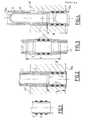
- a layer of chromium 2 with a thickness of between 0 is deposited on the external surface of this tube 1, in three successive annular zones close to the end of the sleeve. , 10 and 0.15 mm.
- the chromium deposits 2 thus constitute three rings surrounding the sleeve 1 in the vicinity of its end.
- the chromium 2 rings have a width close to 4 mm and are spaced from each other by a distance of the same order.
- the deposition can be carried out by an electrolytic or chemical process well known for producing hard chromium layers.
- the rings 2 have a hardness greater than the hardness of the sleeve 1 which is constituted by a nickel alloy of the same shade as that of the tube to be repaired.
- This lower part 6 which is slightly pre-expanded with respect to the current part of the sleeve 1 is introduced into the tube 3 by the inlet face 4a of the tube plate.
- This introduction remains possible despite the presence of the chrome rings, since the thickness of these rings is slightly less than the radial clearance existing between the sleeve 1 and the tube 3, at the time of the introduction of the sleeve.
- the pre-expansion of the lower end of the sleeve only compensates for the reduction in thickness of the tube 3 due to its crimping in the tube plate 4.
- the upper zone 7 of the sleeve 1 undergoes a diametrical expansion inside the tube until the chrome rings 2 ⁇ come into engagement with the interior surface of the tube 3.
- the sleeve 1 is then held inside the tube 3 both by its lower part 6 than by its upper part 7, the diametrical expansion of which has been carried out inside the tube.
- a crimping of the sleeve 1 is then carried out inside the tube 3, in the zones 6 and 7 shown in FIGS. 2 and 3, respectively.
- a dudgeon is introduced comprising rollers driven by a conical rod in the sleeve, at zones 6 and 7 successively.
- the rings 2 and 2 ⁇ become encrusted both in the wall of the sleeve 1 and in the wall of the tube 3 which are made of an alloy of nickel whose hardness is lower than the hardness of the chromium of rings 2 and 2 ⁇ .
- the chrome rings of the lining sleeve penetrate to a depth equal to a quarter of their thickness in the tube 3 and to a depth equal to three quarters of their thickness in the sleeve 1.
- the crimping of the lower part 6 of the sleeve 1 is carried out by rolling the wall of this sleeve against the tube 3 inside the tube plate, only the sleeve 1 undergoing plastic deformation.
- the crimping of the sleeve 1 in its zone 7 is carried out by diametrical expansion of the sleeve 1 and of the tube 3, the deformation of the tube 3 nevertheless remaining in the elastic range while the sleeve 1 undergoes a significant plastic deformation.
- the plug 10 constituted by a hollow cylindrical element whose upper end 10a is closed is introduced inside the tube 3 by the inlet face 4a of the tube plate, after three rings 12 have been deposited.
- of chromium on its lower part 16 slightly pre-expanded.
- the chrome rings 12 have a thickness of between 0.10 and 0.15 mm slightly less than the radial clearance between the pre-expanded part 16 of the plug and the inner surface of the tube 3 crimped inside the plate.
- tubular 4 Each of the chrome rings has a width close to 4 mm and the rings are separated by a space of a length close to 4 mm.
- the fixing of the stopper is completed inside the tube 3 by performing a expansion of the zone 16 inside the tube 3 and of the tube plate 4.
- the chrome rings 12 penetrate, during the expansion operation, both in the tube 3 and in the sleeve 10, to achieve an extremely resistant anchoring of the stopper in the tube 3.
- the junction zones with the tube provide a perfect seal, so that it is not necessary to make a complementary sealing weld at the end of the sleeve or at the end of the plug.
- connection between the tube and the sleeve or the stopper is extremely resistant thanks to the anchoring effect of the rings.
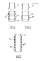
- FIG. 5 shows an alternative embodiment of a cylindrical element 20 which may be a sleeve or a plug intended for a steam generator tube as described above.
- This element 20 comprises a pre-expanded end portion 26 intended to come into the crimped portion of the steam generator tube.
- the rings 22 comprise grooves 23 projecting radially on their outer surface and a smooth inner surface.
- the internal diameter of the rings 22 is such that the rings are in contact with the external surface of the part 26 of the element 20 and threaded slightly in force on this element.
- Their thickness is such that the element 20 provided with its rings 22 can be introduced into the tube to be repaired.
- a sleeve for the repair of a steam generator tube with an internal diameter slightly less than 20 mm, a sleeve was used comprising, in its pre-expanded part 26, three rings such as the rings 22 having a height of 5 mm and a thickness of 0.25 mm spaced 5 mm apart in the axial direction of the tube.
- the rings 22 have on their external surface grooves of a depth corresponding substantially to half the thickness of the rings 22, ie 0.10 to 0.12 mm.
- the ridges 23 are embedded in the inner wall of the tube to ensure a resistant connection between the tube and the sleeve. Sealing is ensured by the effect of successive baffles.
- the smooth inner surface of the rings is crimped against the sleeve in which the ring is embedded.
- This embodiment has the advantage, compared to chromium rings deposited on the external surface of the sleeve, that the nickel alloy rings are unlikely to crack during the expansion of the sleeve.
- the seal obtained is therefore superior.
- FIG. 6 we see a second alternative embodiment of a cylindrical member 30 which can be a plug or a sleeve for plugging or repairing a steam generator tube.
- the cylindrical element 30 has not been pre-expanded and its outside diameter is clearly smaller than the inside diameter of the tube.
- a ring 32 is arranged around the cylindrical element 30 in the region of this element intended to undergo expansion and expansion in the tube to be plugged or to be repaired.
- the ring 32 has grooves 33 projecting radially, both on its external surface and on its internal surface.
- the ring 32 is threaded onto the external surface of the element 30 slightly in force. After introduction of the element 30 into the tube, its expansion is carried out directly without carrying out prior hydraulic expansion. The expansion has the effect of embedding the ridges 33 on the one hand in the tube of the steam generator and on the other hand in the element 30.
- a ring 30 with a height of 15 mm and a thickness of 0.8 mm is used, the clearance between the tube and element 30 being more important than in the case of the previous example.
- the thickness of the streaks is 0.10 to 0.12 mm.
- the incrustation of the ridges 33 ensures both the anchoring and the sealing of the element 30, inside the tube.
- FIG. 7 a third alternative embodiment of a tubular element 35 is seen, the initial outside diameter of which is less than the inside diameter of a tube of a steam generator in which the element 35 is to be fixed.
- This latter embodiment makes it possible to obtain both a very good anchoring of the element 35 in the tube and a very good seal.
- the method according to the invention is therefore extremely efficient and easy to implement and provides a very good seal without the need to weld the cylindrical element attached to the tube.
- rings of any material of sufficient hardness deposited or attached to the surface of the tubular element may be fixed in the tube.
- These rings may include protruding parts of any shape, to facilitate their inlaying in the metal of the tube and the tubular element.
- a continuous deposit of chromium is carried out electrolytically on the end of the cylindrical element, then, when the thickness of this deposit corresponds to the thickness desired for the rings, the electrolysis is stopped and the 'the successive rings are machined by grinding the chromium layer in the annular zones of separation between the rings.
- the chromium deposition can be carried out other than by electrolysis and for example by chemical deposition.
- chromium instead of chromium, another hard metal such as tungsten can be deposited on the cylindrical element.
- a hard metal such as tungsten carbide in a cobalt matrix.
- the thickness of the rings is generally determined by the initial clearance between the tube and the cylindrical element that is fixed in this tube, this thickness having to allow the cylindrical element to be inserted and put in place without difficulty in the tube.
- the width of the rings is determined, as a function of the number of rings, by the resistance and the sealing sought.
- the fixing method applies as well in the case of the lining of steam generator tubes with a sleeve of a length greater than the thickness of the tube plate as in the case of the lining with a short sleeve applicable preferably to peripheral tubes; the crimping of the lower zone of the sleeve with inlaying of the rings of hard material takes place in a zone situated inside the tubular plate and distant from the entry face of this plate, in the case of short sleeving.
- the fixing method according to the invention applies not only to the plugging and lining of steam generator tubes but also to any fixing of hollow cylindrical parts inside a tube, when a very high resistance and very good sealing of the junction zones.
Landscapes
- Engineering & Computer Science (AREA)
- General Engineering & Computer Science (AREA)
- Mechanical Engineering (AREA)
- Physics & Mathematics (AREA)
- Thermal Sciences (AREA)
- Powder Metallurgy (AREA)
- Non-Disconnectible Joints And Screw-Threaded Joints (AREA)
Applications Claiming Priority (2)
| Application Number | Priority Date | Filing Date | Title |
|---|---|---|---|
| FR8608065A FR2599791B1 (fr) | 1986-06-04 | 1986-06-04 | Procede de fixation resistante et etanche d'un element cylindrique creux a l'interieur d'un tube et element cylindrique pour la mise en oeuvre de ce procede |
| FR8608065 | 1986-06-04 |
Publications (2)
| Publication Number | Publication Date |
|---|---|
| EP0248728A1 true EP0248728A1 (de) | 1987-12-09 |
| EP0248728B1 EP0248728B1 (de) | 1990-01-24 |
Family
ID=9336002
Family Applications (1)
| Application Number | Title | Priority Date | Filing Date |
|---|---|---|---|
| EP87401231A Expired - Lifetime EP0248728B1 (de) | 1986-06-04 | 1987-06-02 | Verfahren zum festen und dichten Befestigen eines hohlen, zylindrischen Elementes in das Innere eines Rohres und zylindrisches Element zur Durchführung dieses Verfahrens |
Country Status (5)
| Country | Link |
|---|---|
| US (1) | US4819315A (de) |
| EP (1) | EP0248728B1 (de) |
| DE (1) | DE3761512D1 (de) |
| ES (1) | ES2012402B3 (de) |
| FR (1) | FR2599791B1 (de) |
Cited By (4)
| Publication number | Priority date | Publication date | Assignee | Title |
|---|---|---|---|---|
| EP0291003A1 (de) | 1987-05-15 | 1988-11-17 | ABB Reaktor GmbH | Hohlstopfen zum Verschliessen eines Wärmetauschrohres |
| EP0446841A1 (de) * | 1990-03-15 | 1991-09-18 | ABB Reaktor GmbH | Metallische Hülse zur Àberbrückung einer Leckagestelle eines Rohres |
| CH682942A5 (de) * | 1991-04-22 | 1993-12-15 | Geberit Ag | Verbindungsteil für eine Pressverbindung. |
| WO1997021971A3 (en) * | 1995-12-13 | 1997-08-28 | Westinghouse Electric Corp | Method and joint for sealing a bare hole in a tubesheet |
Families Citing this family (13)
| Publication number | Priority date | Publication date | Assignee | Title |
|---|---|---|---|---|
| US5400827A (en) * | 1990-03-15 | 1995-03-28 | Abb Reaktor Gmbh | Metallic sleeve for bridging a leakage point on a pipe |
| US5667252A (en) * | 1994-09-13 | 1997-09-16 | Framatome Technologies, Inc. | Internal sleeve with a plurality of lands and teeth |
| FR2726885A1 (fr) | 1994-11-15 | 1996-05-15 | Framatome Sa | Procede de fixation resistante et etanche d'une manchette a l'interieur d'un tube metallique et manchette de reparation d'un tube metallique |
| DE19643196A1 (de) * | 1996-10-19 | 1998-04-23 | Andreas Wern | Mechanische Verbindungstechnik für Voll- und Hohlprofile |
| MXPA02003659A (es) * | 1999-10-15 | 2003-05-23 | Siemens Canada Ltd | Metodo para crear una forma de fusion en caliente para el uso con un montaje de induccion de aire. |
| US20060118192A1 (en) * | 2002-08-30 | 2006-06-08 | Cook Robert L | Method of manufacturing an insulated pipeline |
| BRPI0503134B1 (pt) * | 2004-08-02 | 2018-03-20 | Rohm And Haas Company | Método de formação de uma chapa de tubo laminada |
| SE527694C2 (sv) * | 2005-05-10 | 2006-05-16 | Kvaerner Power Ab | Insatstub samt ett system av insatstuber |
| ITMI20062078A1 (it) * | 2006-10-30 | 2008-04-30 | Afl S P A | Raccordo metallico |
| WO2008068550A1 (en) * | 2006-12-06 | 2008-06-12 | Belleli Energy Cpe S.P.A. | Method for isolating or sealing a leaky tube |
| JP5935036B2 (ja) * | 2011-11-11 | 2016-06-15 | パナソニックIpマネジメント株式会社 | 圧縮機及び圧縮機用密封栓 |
| DE102011121204A1 (de) * | 2011-12-16 | 2013-06-20 | Westinghouse Electric Germany Gmbh | Dampferzeugerheizrohrreparaturmittel und Reparaturverfahren |
| US9180509B2 (en) * | 2013-10-24 | 2015-11-10 | The Boeing Company | Cold working holes in a composite and metal stack |
Citations (4)
| Publication number | Priority date | Publication date | Assignee | Title |
|---|---|---|---|---|
| FR1238027A (fr) * | 1958-10-01 | 1960-08-05 | Carlsson & Larsson Ab | Perfectionnements apportés aux accouplements pour tubes |
| GB2079204A (en) * | 1980-06-21 | 1982-01-20 | Balcke Duerr Ag | Methods of Securing a Tube in the Bore of a Wall |
| EP0122610A1 (de) * | 1983-04-14 | 1984-10-24 | Combustion Engineering, Inc. | Mechanischer Rohrstopfen |
| FR2572800A1 (fr) * | 1984-11-06 | 1986-05-09 | Framatome Sa | Procede de reparation par chemisage d'un tube d'un generateur de vapeur et chemise de reparation de ce tube |
Family Cites Families (4)
| Publication number | Priority date | Publication date | Assignee | Title |
|---|---|---|---|---|
| US1953665A (en) * | 1932-11-02 | 1934-04-03 | Henry J Wallace | Pipe connection |
| US2686353A (en) * | 1950-06-06 | 1954-08-17 | Acme Ind Inc | Method of assembling tubes in spacer plates |
| SU518257A1 (ru) * | 1971-02-12 | 1976-06-25 | Предприятие П/Я А-7219 | Способ соединени труб с трубными решетками |
| FR2253977B1 (de) * | 1973-12-10 | 1979-10-19 | Kubota Ltd |
-
1986
- 1986-06-04 FR FR8608065A patent/FR2599791B1/fr not_active Expired
-
1987
- 1987-06-02 EP EP87401231A patent/EP0248728B1/de not_active Expired - Lifetime
- 1987-06-02 ES ES87401231T patent/ES2012402B3/es not_active Expired - Lifetime
- 1987-06-02 DE DE8787401231T patent/DE3761512D1/de not_active Expired - Lifetime
- 1987-06-04 US US07/057,997 patent/US4819315A/en not_active Expired - Fee Related
Patent Citations (4)
| Publication number | Priority date | Publication date | Assignee | Title |
|---|---|---|---|---|
| FR1238027A (fr) * | 1958-10-01 | 1960-08-05 | Carlsson & Larsson Ab | Perfectionnements apportés aux accouplements pour tubes |
| GB2079204A (en) * | 1980-06-21 | 1982-01-20 | Balcke Duerr Ag | Methods of Securing a Tube in the Bore of a Wall |
| EP0122610A1 (de) * | 1983-04-14 | 1984-10-24 | Combustion Engineering, Inc. | Mechanischer Rohrstopfen |
| FR2572800A1 (fr) * | 1984-11-06 | 1986-05-09 | Framatome Sa | Procede de reparation par chemisage d'un tube d'un generateur de vapeur et chemise de reparation de ce tube |
Cited By (5)
| Publication number | Priority date | Publication date | Assignee | Title |
|---|---|---|---|---|
| EP0291003A1 (de) | 1987-05-15 | 1988-11-17 | ABB Reaktor GmbH | Hohlstopfen zum Verschliessen eines Wärmetauschrohres |
| US5022437A (en) * | 1987-05-15 | 1991-06-11 | Brown Boveri Reaktor Gmbh | Hollow plug for blocking a heat exchanger tube |
| EP0446841A1 (de) * | 1990-03-15 | 1991-09-18 | ABB Reaktor GmbH | Metallische Hülse zur Àberbrückung einer Leckagestelle eines Rohres |
| CH682942A5 (de) * | 1991-04-22 | 1993-12-15 | Geberit Ag | Verbindungsteil für eine Pressverbindung. |
| WO1997021971A3 (en) * | 1995-12-13 | 1997-08-28 | Westinghouse Electric Corp | Method and joint for sealing a bare hole in a tubesheet |
Also Published As
| Publication number | Publication date |
|---|---|
| EP0248728B1 (de) | 1990-01-24 |
| FR2599791B1 (fr) | 1988-10-28 |
| ES2012402B3 (es) | 1990-03-16 |
| US4819315A (en) | 1989-04-11 |
| DE3761512D1 (de) | 1990-03-01 |
| FR2599791A1 (fr) | 1987-12-11 |
Similar Documents
| Publication | Publication Date | Title |
|---|---|---|
| EP0248728B1 (de) | Verfahren zum festen und dichten Befestigen eines hohlen, zylindrischen Elementes in das Innere eines Rohres und zylindrisches Element zur Durchführung dieses Verfahrens | |
| EP0181250B1 (de) | Muffeneinsatzverfahren zum Reparieren eines Dampferzeugerrohres und Reparaturmuffe für dieses Rohr | |
| CA2410425C (fr) | Joint filete tubulaire apte a subir une expansion diametrale | |
| EP2601429B2 (de) | Rohrförmige kunststoffverbindungsmuffe für ein rohr mit innenauskleidung | |
| FR2717855A1 (fr) | Procédé pour rendre étanche la liaison entre un chemisage intérieur d'une part, et un puits de forage, un tubage ou une canalisation extérieure d'autre part. | |
| FR2704898A1 (fr) | Structure tubulaire de préforme ou de matrice pour le tubage d'un puits. | |
| EP1805444A1 (de) | Unterwasserrohr mit innenauskleidung | |
| EP3164258B1 (de) | Vorrichtung und verfahren zur installation einer rohrförmigen verbindungsmuffe für ein rohr mit einer inneren auskleidung | |
| EP0782679B1 (de) | Vorrichtung zum dichten verbinden mit mindestens einem zylindrischen element | |
| EP3535111B1 (de) | Verfahren zur montage von thermoplastischen rohren durch induktionsschweissen | |
| BE1006248A3 (fr) | Bouchon pour tube et procede de bouchage de tubes. | |
| FR2585817A1 (fr) | Procede et dispositif de traitement de surface pour les echangeurs de chaleur | |
| CH663264A5 (fr) | Procede de protection contre la corrosion d'un tube de generateur de vapeur et dispositif pour la mise en oeuvre de ce procede. | |
| FR2676525A1 (fr) | Bouchon pour obturation de tube et procede pour obturer un tube. | |
| EP0196971B1 (de) | Wiederherstellungsverfahren durch Verkleidung eines Dampfgeneratorrohres | |
| FR2607235A1 (fr) | Procede de reparation ou de protection d'une extremite de tube metallique d'echangeur de chaleur, et manchon pour sa mise en oeuvre | |
| FR2588788A1 (fr) | Procede de brasage a deplacement continu pour souder un manchon dans un tube | |
| EP0699499B1 (de) | Reparaturverfahren einer heterogenen Schweissverbindung zwischen einem Stutzen eines Nuklearreaktorbestandteils und einer Rohrleitung | |
| WO2000037194A1 (fr) | Procede de liaison de deux pieces tubulaires coaxiales outil pour realiser cette liaison et utilisation | |
| EP0713049A1 (de) | Verfahren zum festen und dichten Befestigen einer Muffe in das Innere eines Rohres aus Metall und Reparaturmuffe für ein Rohr aus Metall | |
| FR3132784A1 (fr) | Méthode de réparation d’un générateur de vapeur d’un réacteur nucléaire, générateur de vapeur correspondant | |
| FR2723869A1 (fr) | Procede de reparation d'une liaison soudee heterogene entre une tubulure d'un composant d'un reacteur nucleaire et une tuyauterie. | |
| OA21519A (fr) | Conduite pour le transport de fluides avec contrôle du flambement de la chemise interne anticorrosion. | |
| FR3163198A1 (fr) | Dispositif et méthode de maintenance d’une enceinte d’un réacteur à pression | |
| FR2669255A1 (fr) | Procede et dispositif d'extraction d'un element cylindrique tel qu'un bouchon d'un tube de petit diametre. |
Legal Events
| Date | Code | Title | Description |
|---|---|---|---|
| PUAI | Public reference made under article 153(3) epc to a published international application that has entered the european phase |
Free format text: ORIGINAL CODE: 0009012 |
|
| AK | Designated contracting states |
Kind code of ref document: A1 Designated state(s): BE CH DE ES FR GB IT LI SE |
|
| 17P | Request for examination filed |
Effective date: 19871029 |
|
| 17Q | First examination report despatched |
Effective date: 19890112 |
|
| GRAA | (expected) grant |
Free format text: ORIGINAL CODE: 0009210 |
|
| AK | Designated contracting states |
Kind code of ref document: B1 Designated state(s): BE CH DE ES FR GB IT LI SE |
|
| ITF | It: translation for a ep patent filed | ||
| REF | Corresponds to: |
Ref document number: 3761512 Country of ref document: DE Date of ref document: 19900301 |
|
| GBT | Gb: translation of ep patent filed (gb section 77(6)(a)/1977) | ||
| PLBE | No opposition filed within time limit |
Free format text: ORIGINAL CODE: 0009261 |
|
| STAA | Information on the status of an ep patent application or granted ep patent |
Free format text: STATUS: NO OPPOSITION FILED WITHIN TIME LIMIT |
|
| 26N | No opposition filed | ||
| ITTA | It: last paid annual fee | ||
| PGFP | Annual fee paid to national office [announced via postgrant information from national office to epo] |
Ref country code: CH Payment date: 19930524 Year of fee payment: 7 |
|
| PGFP | Annual fee paid to national office [announced via postgrant information from national office to epo] |
Ref country code: GB Payment date: 19930526 Year of fee payment: 7 |
|
| PGFP | Annual fee paid to national office [announced via postgrant information from national office to epo] |
Ref country code: DE Payment date: 19930527 Year of fee payment: 7 |
|
| PGFP | Annual fee paid to national office [announced via postgrant information from national office to epo] |
Ref country code: BE Payment date: 19930623 Year of fee payment: 7 |
|
| PGFP | Annual fee paid to national office [announced via postgrant information from national office to epo] |
Ref country code: SE Payment date: 19930629 Year of fee payment: 7 Ref country code: FR Payment date: 19930629 Year of fee payment: 7 |
|
| PGFP | Annual fee paid to national office [announced via postgrant information from national office to epo] |
Ref country code: ES Payment date: 19930630 Year of fee payment: 7 |
|
| PG25 | Lapsed in a contracting state [announced via postgrant information from national office to epo] |
Ref country code: GB Effective date: 19940602 |
|
| PG25 | Lapsed in a contracting state [announced via postgrant information from national office to epo] |
Ref country code: SE Effective date: 19940603 Ref country code: ES Free format text: LAPSE BECAUSE OF THE APPLICANT RENOUNCES Effective date: 19940603 |
|
| PG25 | Lapsed in a contracting state [announced via postgrant information from national office to epo] |
Ref country code: LI Effective date: 19940630 Ref country code: CH Effective date: 19940630 Ref country code: BE Effective date: 19940630 |
|
| BERE | Be: lapsed |
Owner name: FRAMATOME Effective date: 19940630 |
|
| EUG | Se: european patent has lapsed |
Ref document number: 87401231.3 Effective date: 19950110 |
|
| GBPC | Gb: european patent ceased through non-payment of renewal fee |
Effective date: 19940602 |
|
| PG25 | Lapsed in a contracting state [announced via postgrant information from national office to epo] |
Ref country code: FR Effective date: 19950228 |
|
| REG | Reference to a national code |
Ref country code: CH Ref legal event code: PL |
|
| PG25 | Lapsed in a contracting state [announced via postgrant information from national office to epo] |
Ref country code: DE Effective date: 19950301 |
|
| EUG | Se: european patent has lapsed |
Ref document number: 87401231.3 |
|
| REG | Reference to a national code |
Ref country code: FR Ref legal event code: ST |
|
| REG | Reference to a national code |
Ref country code: ES Ref legal event code: FD2A Effective date: 19991007 |
|
| PG25 | Lapsed in a contracting state [announced via postgrant information from national office to epo] |
Ref country code: IT Free format text: LAPSE BECAUSE OF NON-PAYMENT OF DUE FEES;WARNING: LAPSES OF ITALIAN PATENTS WITH EFFECTIVE DATE BEFORE 2007 MAY HAVE OCCURRED AT ANY TIME BEFORE 2007. THE CORRECT EFFECTIVE DATE MAY BE DIFFERENT FROM THE ONE RECORDED. Effective date: 20050602 |