EP0248664A2 - Crampons pour articles chaussants - Google Patents
Crampons pour articles chaussants Download PDFInfo
- Publication number
- EP0248664A2 EP0248664A2 EP87304944A EP87304944A EP0248664A2 EP 0248664 A2 EP0248664 A2 EP 0248664A2 EP 87304944 A EP87304944 A EP 87304944A EP 87304944 A EP87304944 A EP 87304944A EP 0248664 A2 EP0248664 A2 EP 0248664A2
- Authority
- EP
- European Patent Office
- Prior art keywords
- boss
- attachment portion
- spigot
- collar
- stud
- Prior art date
- Legal status (The legal status is an assumption and is not a legal conclusion. Google has not performed a legal analysis and makes no representation as to the accuracy of the status listed.)
- Granted
Links
Images


Classifications
-
- A—HUMAN NECESSITIES
- A43—FOOTWEAR
- A43C—FASTENINGS OR ATTACHMENTS OF FOOTWEAR; LACES IN GENERAL
- A43C13/00—Wear-resisting attachments
- A43C13/04—Cleats; Simple studs; Screws; Hob-nails
-
- A—HUMAN NECESSITIES
- A43—FOOTWEAR
- A43C—FASTENINGS OR ATTACHMENTS OF FOOTWEAR; LACES IN GENERAL
- A43C15/00—Non-skid devices or attachments
- A43C15/16—Studs or cleats for football or like boots
- A43C15/161—Studs or cleats for football or like boots characterised by the attachment to the sole
Definitions
- This invention relates to studs for articles of footwear and is particularly, though not exclusively, concerned with studs for football boots and like sportswear.
- the present invention consists in a stud for an article of footwear, which stud comprises an attachment portion and a ground-engaging boss, both the attachment portion and the boss being made as mouldings of plastics or similar materials, the attachment portion comprising an externally screw-threaded spigot, for engagement with a complementary screw-thread in a socket in or on an article of footwear, and a body presenting means for engagement by a tool for assisting in screwing the stud tightly into the socket, the boss projecting from the body in a direction opposite to that in which the spigot projects.
- the attachment portion and the boss are preferably made from different materials as the functions of these components are different from each other.
- the attachment portion is preferably made from a material that is relatively hard and inflexible but is not brittle, while the boss is preferably made from a material that is more flexible and resilient but is none the less tough.
- the attachment portion may be made from an acetal resin, while the boss may be made from polypropylene, nylon 6 or polyurethane.
- the present invention consists in a method of making a stud as set out in the last preceding paragraph but one, which method comprises moulding the attachment portion and then moulding the boss on to the attachment portion.
- the boss is preferably moulded onto the attachment portion so as to become permanently attached to the attachment portion.
- the attachment portion preferably incorporates one or more apertures such that during the formation of the boss, boss-forming material can flow into or through the aperture or apertures to enable the boss to become permanently interlocked with the attachment portion.
- the boss-forming material forms enlarged portions at each end of the aperture, or at each end of each aperture, so that the boss-forming material becomes mechanically interlocked with the attachment portion.
- boss-forming material flows through a plurality of apertures in the attachment portion and joins up to form a plug or ring within a recess in the attachment portion.
- the body of the attachment portion may comprise a central stiffening support comprising a hub which is aligned axially with the spigot, the hub being supported by means of a plurality of spokes extending radially outwards to an annular portion of the body forming a collar; in such an arrangement the boss-forming material can flow through apertures between the spokes and join up as a ring or plug beyond the spokes.
- the attachment portion and the boss are made of materials of different colours.
- the arrangement is preferably such that, in use, when the boss is partially worn away, there is revealed part of the attachment portion within the boss constituting wear-indicating means, the appearance of that means signalling to the user that the stud should be discarded and replaced by a new one. It will be obvious that the greater is the contrast between the colours, the more readily the wear-indicating means will be seen.
- the attachment portion includes a stiffening support
- the wear-indicating means may be constituted by an end portion of the stiffening support.
- the body of the attachment portion of the stud preferably includes an outwardly directed flange for engagement with the underside of an article of footwear or with an end of a socket in an article of footwear or with both.
- the two studs illustrated are intended for use as football studs.
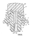
- an attachment portion 1 is initially made, and a boss 2 is subsequently moulded on to it.
- the attachment portion 1 is made as a moulding of a plastics material that is relatively hard, inflexible and tough; an acetal resin such as 'DELRIN' has been found to be suitable.
- the attachment portion includes a spigot 3 formed with an external screwthread 4 by means of which the stud can be secured in an internally threaded socket in a football boot.
- the form of the thread 4 is similar to that described and illustrated in the specification of the aforementioned British Patent No. 2 115 683 and will not be further described here.
- the remainder of the attachment portion 1 constitutes a body.
- the body includes an outwardly directed annular flange 5 which in use abuts the sole of the football boot around the socket or abuts the rim of the socket, or abuts both.
- An annular retaining ring 6 projects from the flange 5.
- the purpose of the ring is similar to that of the annular retaining ring described and illustrated in the specification of British patent application No. 8518677 (Publication No. 2163037A). The ring 6 will therefore not be further described herein.
- the flange 5 and ring 6 are coaxial with the spigot 3.
- the flange 5 extends outwards from an annular collar 7, the spigot 3 and collar 7 projecting axially in opposite directions from the flange.
- the inner face of the collar is of frusto-conical shape but the outer face of the collar is formed with six similar flats disposed uniformly and symmetrically around the collar. In use the flats can be engaged by a spanner or similar tool used to tighten the stud into the socket or to loosen the stud when it is to be removed from the socket.
- a central frusto-conical stiffening support comprising a hub 8, which is axially aligned with the spigot and projects axially beyond the collar in the direction away from the spigot.
- An axial hole 9 extends through the spigot and the hub 8. That end of the hole which opens through the spigot is flared, as indicated at 10, the remainder of the hole being of cylindrical shape.
- a broader end of the hub, adjacent to the spigot, is integrally connected to an adjacent part of the collar by a plurality of radially extending spokes 11. In the example illustrated there are six spokes, but if desired the number of spokes may be different from that.
- Apertures 12 extend axially through the attachment portion between the spokes.
- An integral buttress 13 stems from each spoke 11 and extends in a generally axial direction along the hub 8. End portions 14 of the buttresses project axially and serve as wear-indicating means. In modified constructions, the number and positions of the buttresses may be varied.
- the attachment portion is made in a relatively simple mould, of which a rotatable first part defines the threaded spigot 3, a second part defines the retaining ring 6 and the adjacent faces of the flange and spokes, and a third part which defines the other faces of the flange, the collar, the hub, the apertures 12 and the spokes and buttresses.
- a rivet 15 is placed in the mould.
- the rivet has a cylindrical stem 16 with a head 17 at one end and a counterbore 18 at the other end.
- the rivet is located on a metal pin which enters the counterbore 18.
- the head 17 which has a tapered edge face, engages the tapered interior of the third part of the mould. If the rivet is not in a truly axial position, it is automatically guided to such a position as the mould closes, the head 17 being centralised by the tapered interior of the third part of the mould.
- the pin supporting the rivet is moved axially in the direction of the head. This causes a frusto-conical shoulder on the pin to enter the counterbore 18 and to flare it outwards, as illustrated at 19.
- the third part of the mould can engage the head of the rivet and force the rivet axially onto the frusto-conical shoulder to form the flared portion 19.
- the rivet 15 may be made of any suitable material. Its prime purpose is to stiffen the stud, for it will be appreciated that in use, the spigot is located within a socket in the boot and when the boss is kicked along the ground surface, there are strong lateral forces tending to bend or break the stud about mid-way along its length.
- the rivet may be made of steel or of some other metal such as an aluminium alloy.
- the stem 16 of the rivet 15 defines the bore of the axial hole 9 in the attachment portion and that the underside of the head 17 of the rivet defines an end face of the hub 8. Moreover, the tapered edge face of the head defines part of an inside face of the projecting end portion 14 of each buttress 13.
- the presence of the rivet 15 also serves to limit the radial thickness of the spigot 3 and hub 8. This avoids the possibility of cavities forming in those parts during cooling and also reduces the cooling time required for the attachment portion.
- the attachment portion 1 When the attachment portion 1 has cooled it may have shrunk to an extent such that the rivet 15 becomes axially loose in the attachment portion. This may not matter as the rivet does not serve to secure components together. Nevertheless it might provide an opportunity for moisture or dirt to enter between the flared end portion 19 of the rivet and the flared end 9 of the hole in the attachment portion.
- the pin on which the rivet is located can be moved axially to a further small extent, before the mould is opened, thereby causing the shoulder on the pin to enlarge the flared end 19 slightly and press it against the moulding.
- the third part of the mould is withdrawn in an axial direction and the first part of the mould is rotated through part of one turn so as to shift the moulding axially a short distance relative to the second part of the mould.
- the boss 2 is then moulded on to the attachment portion 1 and the rivet 15.
- a fourth mould part is substituted for the third mould part and plastics material for forming the boss is injected into the resulting cavity.
- the boss 2 is formed from a plastics material, such as polyurethane, that is rather more flexible and resilient than that from which the attachment portion is formed.
- An end portion 20 of the boss is of generally frusto-conical shape terminating in an end face which is flat or slightly domed. This end portion 20 abuts an annular end face of the collar 7.
- the boss embraces the buttresses 13, filling the gap between the collar 7 and the hub 8, the boss so becoming radially located within the collar.
- the boss seats against the head 17 of the rivet.
- the boss also includes anchorage portions which secure it mechanically to the attachment portion 1.
- the anchorage portions comprise fingers 21, which extend through the apertures 12 between the spokes 11, and a ring 22 at the ends of the fingers and which is moulded into the gap beyond the spokes, produced when the attachment portion was shifted axially on rotation of the first part of the mould. It will thus be seen that the attachment portion is held between the ring 22 and the end portion 20 of the boss 2, so that the boss and attachment portion are positively secured together.
- Multi-cavity tools may be provided to enable a plurality of studs to be formed at the same time.
- the end portion 20 of the boss will become progressively worn away. It is of course desirable that the stud be discarded and replaced with a new one before the wear becomes excessive.
- the boss has been worn away to a certain extent the end portions 14 of the buttresses will start to become exposed. This can signal that the time has come to discard the stud.
- the material from which the boss 2 is formed is preferably of a colour quite different from that of the material from which the attachment portion 1 is made. This enables the exposure of the end portions 14 to become immediately visible.
- the shape and position of the end portions 14 can to some extent be varied in different models of stud so that they become visible after different degrees of wear.
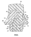
- the second stud is of similar basic construction to the first and can be manufactured in a similar manner. It comprises an attachment portion 25 of an acetal resin, and a boss 26 of polyurethane moulded on to it.
- the attachment portion includes a spigot 27 formed with an external screwthread 28 of similar form to the thread 4 of the first stud.
- the remainder of the attachment portion 25 constitutes a body comprising portions providing a collar 29, a flange 30 and a retaining ring 31 in a generally similar arrangement to the first stud, the collar, flange and ring all being coaxial with the spigot 27.
- the flange 30 extends radially outwards from the annular collar 29.
- the spigot 27 and the collar 29 project axially in opposite directions from the flange.
- An inclined outer surface 32 of the body extends down from a minimum diameter at the outer edge of a flat annular top end face 33 of the collar to a maximum diameter at the outer edge of the flange 30, as seen in Figure 5.
- the inner surface 35 of the collar extends down from a maximum diameter at the inner edge of the annular collar end face 33 to a minimum diameter where it meets an inner end of an axial passage 36 extending right through the spigot 27.
- the inner surface 35 is cylindrical, or nearly cylindrical, for the major part of its axial length, and thereafter generally frusto-conical as it converges to the passage 36.
- a central stiffening support comprising an elongate cylindrical hub 37 which is axially aligned with the spigot 27.
- the hub 37 projects axially beyond the end face 33 of the collar in the direction away from the spigot.
- the hub 37 is so mounted with its bottom end 39 axially spaced from the spigot and the bottom end of the collar. Bottom edges 40 of the webs extend between the hub end 39 and the bottom end of the inner surface 35 of the collar (at the inner end of passage 36) the hub being of lesser diameter than the inner end of the passage. Apertures so created between the spokes 38 open out at the bottom end of the spokes into a chamber constituted by the passage 36 and the space bounded by the bottom edges 40 of the spokes, the hub end 39 and the passage 36.
- a top end portion of the hub 37, projecting axially beyond the collar 29, can serve as wear-indicating means in a similar manner to the end portions of the buttresses in the first stud.
- the boss-forming plastics material forms an outer end portion which surrounds the hub 37 and is seated on the collar end face 33.
- the material furthermore flows down between the spokes 38 to fill the chamber beneath the hub, including the passage 36 in the spigot.
- Attachment fingers 41 are so formed between the spokes, the fingers being joined up as a plug 42 beneath the hub. The attachment portion is thus held between the plug 42 and the outer end portion of the boss 26, so that the two parts of the stud moulding are positively secured together.
- the relative proportions of the inside diameter of the collar 29, the diameter of the passage 36 through the spigot, the diameter of the hub 37, and the spacing of the hub from the passage 36, are chosen to ensure a good entry for the boss-forming material to flow through and form the plug 42.
Landscapes
- Footwear And Its Accessory, Manufacturing Method And Apparatuses (AREA)
- Slide Fasteners, Snap Fasteners, And Hook Fasteners (AREA)
- Pharmaceuticals Containing Other Organic And Inorganic Compounds (AREA)
Priority Applications (1)
| Application Number | Priority Date | Filing Date | Title |
|---|---|---|---|
| AT87304944T ATE60493T1 (de) | 1986-06-06 | 1987-06-04 | Dorne fuer schuhwerk. |
Applications Claiming Priority (2)
| Application Number | Priority Date | Filing Date | Title |
|---|---|---|---|
| GB8613733 | 1986-06-06 | ||
| GB868613733A GB8613733D0 (en) | 1986-06-06 | 1986-06-06 | Studs for footwear |
Publications (3)
| Publication Number | Publication Date |
|---|---|
| EP0248664A2 true EP0248664A2 (fr) | 1987-12-09 |
| EP0248664A3 EP0248664A3 (en) | 1988-07-27 |
| EP0248664B1 EP0248664B1 (fr) | 1991-01-30 |
Family
ID=10599021
Family Applications (1)
| Application Number | Title | Priority Date | Filing Date |
|---|---|---|---|
| EP87304944A Expired - Lifetime EP0248664B1 (fr) | 1986-06-06 | 1987-06-04 | Crampons pour articles chaussants |
Country Status (9)
| Country | Link |
|---|---|
| US (1) | US4791692A (fr) |
| EP (1) | EP0248664B1 (fr) |
| KR (1) | KR880000051A (fr) |
| AT (1) | ATE60493T1 (fr) |
| AU (1) | AU599659B2 (fr) |
| BR (1) | BR8702861A (fr) |
| DE (1) | DE3767775D1 (fr) |
| ES (1) | ES2019939B3 (fr) |
| GB (2) | GB8613733D0 (fr) |
Cited By (2)
| Publication number | Priority date | Publication date | Assignee | Title |
|---|---|---|---|---|
| WO1991015131A1 (fr) * | 1990-04-03 | 1991-10-17 | Trisport Limited | Crampons et douilles pour chaussures a crampons |
| US6301806B1 (en) | 1998-11-02 | 2001-10-16 | Adidas International B.V. | Detachable cleat system |
Families Citing this family (24)
| Publication number | Priority date | Publication date | Assignee | Title |
|---|---|---|---|---|
| EP0377911A3 (fr) * | 1989-01-10 | 1991-07-03 | BIASIOTTO CONTRAFFORTI DI BIASIOTTO VITTORIO & C. S.A.S. | Semelle pour chaussures de sport |
| US5377431A (en) * | 1993-06-15 | 1995-01-03 | Walker; Andrew S. | Directionally yieldable cleat assembly |
| USD390693S (en) | 1997-02-18 | 1998-02-17 | Curley Jr John J | Footwear cleat |
| US5887371A (en) | 1997-02-18 | 1999-03-30 | Curley, Jr.; John J. | Footwear cleat |
| US6041461A (en) * | 1998-02-25 | 2000-03-28 | Yugenkaisha Shinjo Seisakusho | Spike for baseball shoes |
| US7047674B1 (en) * | 1999-05-31 | 2006-05-23 | Bruce Henry Garvie | Cleat for footwear |
| US6834445B2 (en) | 2002-07-16 | 2004-12-28 | Softspikes, Llc | Shoe cleat with improved traction |
| US6834446B2 (en) | 2002-08-27 | 2004-12-28 | Softspikes, Llc | Indexable shoe cleat with improved traction |
| DE10241153B3 (de) | 2002-09-05 | 2004-04-08 | Adidas International Marketing B.V. | Stollen und Schuh |
| US7040043B2 (en) | 2003-08-11 | 2006-05-09 | Softspikes, Llc | Shoe cleat |
| US9003921B2 (en) * | 2007-10-10 | 2015-04-14 | The Hive Global | Removable pedal platform |
| US8291621B2 (en) * | 2008-04-03 | 2012-10-23 | Nike, Inc. | Article of footwear with a cleat member |
| US8945449B2 (en) | 2011-04-21 | 2015-02-03 | Nike, Inc. | Method for making a cleated plate |
| US9220319B2 (en) | 2012-05-15 | 2015-12-29 | Nike, Inc. | Spike for footwear having rigid portion and resilient portion |
| US10221887B2 (en) | 2012-12-06 | 2019-03-05 | The Hive Global, Inc | Self locking bearing preload adjuster |
| US10562588B2 (en) | 2015-09-01 | 2020-02-18 | The Hive Global, Inc | Bicycle cassette with locking connection |
| SE542885C2 (sv) * | 2016-02-29 | 2020-08-04 | Malma Dental Ab | Broddhålsskydd för en hästsko |
| US11142280B2 (en) | 2016-03-24 | 2021-10-12 | The Hive Global, Inc. | Bicycle crank with spindle attachment structure |
| CN111542471A (zh) | 2017-08-21 | 2020-08-14 | 劲锋铁马股份有限公司 | 具有夹紧连接的自行车塔轮 |
| US11330869B2 (en) | 2018-05-08 | 2022-05-17 | Kicks Industries, Inc. | Footwear cleat |
| US11932351B2 (en) | 2020-07-17 | 2024-03-19 | The Hive Global, Inc. | Conical bicycle cassette sprocket structure |
| US12233975B2 (en) | 2021-03-26 | 2025-02-25 | The Hive Global Inc. | Telescopic bicycle seatpost with adjustable height and fixed frame insertion |
| US12030586B2 (en) | 2021-07-12 | 2024-07-09 | The Hive Global, Inc. | Seal for bicycle crank with differential chainring motion |
| US12532945B2 (en) * | 2023-02-28 | 2026-01-27 | Nike, Inc. | Sole structures, and articles of footwear formed therefrom |
Family Cites Families (13)
| Publication number | Priority date | Publication date | Assignee | Title |
|---|---|---|---|---|
| GB1402135A (en) * | 1972-07-20 | 1975-08-06 | Botterill Sons Ltd W | Studs for sports shoes or boots |
| GB1378461A (en) * | 1972-12-04 | 1974-12-27 | Brooker B F | Studs for footwear |
| DE2307678A1 (de) * | 1973-02-16 | 1974-08-22 | Bernhard Frederick Brooker | Stollen fuer schuhe, insbesondere fuer sportschuhe |
| US3911600A (en) * | 1974-01-05 | 1975-10-14 | Adolf Dassler | Exchangeable gripper element |
| DE2733846A1 (de) * | 1977-07-27 | 1979-02-08 | Moelde Gustav Moeller Kg | Schraubstollen fuer sportschuhe |
| DE7801261U1 (de) * | 1978-01-18 | 1978-04-27 | Sportartikelfabrik Karl Uhl Gmbh, 7460 Balingen | Aus Kunststoff oder Gummi bestehender Stollen für Sportschuhe, insbesondere Schraubstollen |
| DE3015116A1 (de) * | 1980-04-19 | 1981-10-22 | Adidas Sportschuhfabriken Adi Dassler Kg, 8522 Herzogenaurach | Elastischer stollen fuer fussballschuhe o.dgl. |
| DE3112389A1 (de) * | 1981-03-28 | 1982-10-07 | Werner 8520 Erlangen Frör | Einstueckiges greifelement fuer sportschuhe |
| AU8318782A (en) * | 1981-05-15 | 1982-11-18 | Dowty Seals Limited | Studs for footwear |
| FR2507875A1 (fr) * | 1981-06-23 | 1982-12-24 | Patrick Sa | Crampon en matiere plastique pour chaussure de sport |
| GB2115683B (en) * | 1982-02-17 | 1985-08-29 | Triman Ltd | Studded footwear |
| FR2539595B1 (fr) * | 1983-01-20 | 1985-11-22 | Patrick Sa | Crampon pour chaussure de sport notamment de football, de rugby ou autre |
| GB8419182D0 (en) * | 1984-07-27 | 1984-08-30 | Triman Ltd | Studs for footwear |
-
1986
- 1986-06-06 GB GB868613733A patent/GB8613733D0/en active Pending
-
1987
- 1987-06-01 AU AU73697/87A patent/AU599659B2/en not_active Ceased
- 1987-06-02 KR KR870005570A patent/KR880000051A/ko not_active Withdrawn
- 1987-06-04 EP EP87304944A patent/EP0248664B1/fr not_active Expired - Lifetime
- 1987-06-04 AT AT87304944T patent/ATE60493T1/de active
- 1987-06-04 GB GB8713058A patent/GB2191079B/en not_active Expired
- 1987-06-04 ES ES87304944T patent/ES2019939B3/es not_active Expired - Lifetime
- 1987-06-04 DE DE8787304944T patent/DE3767775D1/de not_active Expired - Lifetime
- 1987-06-05 US US07/058,518 patent/US4791692A/en not_active Expired - Fee Related
- 1987-06-05 BR BR8702861A patent/BR8702861A/pt not_active IP Right Cessation
Cited By (4)
| Publication number | Priority date | Publication date | Assignee | Title |
|---|---|---|---|---|
| WO1991015131A1 (fr) * | 1990-04-03 | 1991-10-17 | Trisport Limited | Crampons et douilles pour chaussures a crampons |
| AU642251B2 (en) * | 1990-04-03 | 1993-10-14 | Trisport Limited | Studs and sockets for studded footwear |
| US6301806B1 (en) | 1998-11-02 | 2001-10-16 | Adidas International B.V. | Detachable cleat system |
| US6421937B2 (en) | 1998-11-02 | 2002-07-23 | Adidas International B.V. | Detachable cleat system |
Also Published As
| Publication number | Publication date |
|---|---|
| ATE60493T1 (de) | 1991-02-15 |
| DE3767775D1 (de) | 1991-03-07 |
| GB8713058D0 (en) | 1987-07-08 |
| GB2191079B (en) | 1989-12-06 |
| US4791692A (en) | 1988-12-20 |
| BR8702861A (pt) | 1988-03-01 |
| KR880000051A (ko) | 1988-03-23 |
| ES2019939B3 (es) | 1991-07-16 |
| GB8613733D0 (en) | 1986-07-09 |
| GB2191079A (en) | 1987-12-09 |
| EP0248664B1 (fr) | 1991-01-30 |
| EP0248664A3 (en) | 1988-07-27 |
| AU599659B2 (en) | 1990-07-26 |
| AU7369787A (en) | 1987-12-10 |
Similar Documents
| Publication | Publication Date | Title |
|---|---|---|
| EP0248664B1 (fr) | Crampons pour articles chaussants | |
| US4445289A (en) | Plastic spike for sports shoe | |
| US4587748A (en) | Studded footwear | |
| US4723366A (en) | Traction cleat with reinforced radial support | |
| US5410823A (en) | Replaceable golf cleat | |
| US5243775A (en) | Sports-shoe sole and a gripper connected to such a sole | |
| US4205466A (en) | Carriers for studs for footwear | |
| JP3260365B2 (ja) | スタッド付き履物用のスタッド及びソケット | |
| US6272774B1 (en) | Shoe cleats | |
| US5572807A (en) | Composite, wear-resistant stud for sport shoes | |
| US20090077833A1 (en) | Detachable Cleat Arrangement | |
| US5065534A (en) | Studs for footwear | |
| US5027532A (en) | Removable traction cleat with reinforced radial support | |
| JPH0125562B2 (fr) | ||
| JP3824859B2 (ja) | 靴用滑り止め | |
| GB2160146A (en) | Studded footwear | |
| US2292299A (en) | Athletic shoe | |
| GB2115683A (en) | Studded footwear | |
| US7047674B1 (en) | Cleat for footwear | |
| GB1564903A (en) | Socket for a stud for footwear | |
| EP0163823B1 (fr) | Crampon vissé pour chaussures de sport | |
| US5400680A (en) | Golf shoe spike wrench | |
| KR200335974Y1 (ko) | 구두 뒷굽의 착탈구조 | |
| US20060162189A1 (en) | Studded footwear | |
| KR200251316Y1 (ko) | 골프화용 스파이크 |
Legal Events
| Date | Code | Title | Description |
|---|---|---|---|
| PUAI | Public reference made under article 153(3) epc to a published international application that has entered the european phase |
Free format text: ORIGINAL CODE: 0009012 |
|
| AK | Designated contracting states |
Kind code of ref document: A2 Designated state(s): AT BE CH DE ES FR GB GR IT LI LU NL SE |
|
| PUAL | Search report despatched |
Free format text: ORIGINAL CODE: 0009013 |
|
| AK | Designated contracting states |
Kind code of ref document: A3 Designated state(s): AT BE CH DE ES FR GB GR IT LI LU NL SE |
|
| 17P | Request for examination filed |
Effective date: 19881230 |
|
| RAP1 | Party data changed (applicant data changed or rights of an application transferred) |
Owner name: TRISPORT LIMITED |
|
| 17Q | First examination report despatched |
Effective date: 19891129 |
|
| GRAA | (expected) grant |
Free format text: ORIGINAL CODE: 0009210 |
|
| AK | Designated contracting states |
Kind code of ref document: B1 Designated state(s): AT BE CH DE ES FR GR IT LI LU NL SE |
|
| PG25 | Lapsed in a contracting state [announced via postgrant information from national office to epo] |
Ref country code: GR Free format text: LAPSE BECAUSE OF FAILURE TO SUBMIT A TRANSLATION OF THE DESCRIPTION OR TO PAY THE FEE WITHIN THE PRESCRIBED TIME-LIMIT Effective date: 19910130 |
|
| REF | Corresponds to: |
Ref document number: 60493 Country of ref document: AT Date of ref document: 19910215 Kind code of ref document: T |
|
| REF | Corresponds to: |
Ref document number: 3767775 Country of ref document: DE Date of ref document: 19910307 |
|
| ET | Fr: translation filed | ||
| ITF | It: translation for a ep patent filed | ||
| PG25 | Lapsed in a contracting state [announced via postgrant information from national office to epo] |
Ref country code: LU Free format text: LAPSE BECAUSE OF NON-PAYMENT OF DUE FEES Effective date: 19910630 |
|
| PLBE | No opposition filed within time limit |
Free format text: ORIGINAL CODE: 0009261 |
|
| STAA | Information on the status of an ep patent application or granted ep patent |
Free format text: STATUS: NO OPPOSITION FILED WITHIN TIME LIMIT |
|
| 26N | No opposition filed | ||
| EAL | Se: european patent in force in sweden |
Ref document number: 87304944.9 |
|
| PGFP | Annual fee paid to national office [announced via postgrant information from national office to epo] |
Ref country code: BE Payment date: 19950328 Year of fee payment: 9 |
|
| PGFP | Annual fee paid to national office [announced via postgrant information from national office to epo] |
Ref country code: SE Payment date: 19950424 Year of fee payment: 9 |
|
| PGFP | Annual fee paid to national office [announced via postgrant information from national office to epo] |
Ref country code: CH Payment date: 19950510 Year of fee payment: 9 |
|
| PGFP | Annual fee paid to national office [announced via postgrant information from national office to epo] |
Ref country code: ES Payment date: 19950516 Year of fee payment: 9 |
|
| PGFP | Annual fee paid to national office [announced via postgrant information from national office to epo] |
Ref country code: FR Payment date: 19950609 Year of fee payment: 9 |
|
| PGFP | Annual fee paid to national office [announced via postgrant information from national office to epo] |
Ref country code: NL Payment date: 19950627 Year of fee payment: 9 |
|
| PGFP | Annual fee paid to national office [announced via postgrant information from national office to epo] |
Ref country code: AT Payment date: 19950628 Year of fee payment: 9 |
|
| PGFP | Annual fee paid to national office [announced via postgrant information from national office to epo] |
Ref country code: DE Payment date: 19950821 Year of fee payment: 9 |
|
| PG25 | Lapsed in a contracting state [announced via postgrant information from national office to epo] |
Ref country code: AT Effective date: 19960604 |
|
| PG25 | Lapsed in a contracting state [announced via postgrant information from national office to epo] |
Ref country code: SE Effective date: 19960605 Ref country code: ES Free format text: LAPSE BECAUSE OF THE APPLICANT RENOUNCES Effective date: 19960605 |
|
| PG25 | Lapsed in a contracting state [announced via postgrant information from national office to epo] |
Ref country code: LI Effective date: 19960630 Ref country code: CH Effective date: 19960630 Ref country code: BE Effective date: 19960630 |
|
| BERE | Be: lapsed |
Owner name: TRISPORT LTD Effective date: 19960630 |
|
| PG25 | Lapsed in a contracting state [announced via postgrant information from national office to epo] |
Ref country code: NL Effective date: 19970101 |
|
| REG | Reference to a national code |
Ref country code: CH Ref legal event code: PL |
|
| PG25 | Lapsed in a contracting state [announced via postgrant information from national office to epo] |
Ref country code: FR Effective date: 19970228 |
|
| PG25 | Lapsed in a contracting state [announced via postgrant information from national office to epo] |
Ref country code: DE Effective date: 19970301 |
|
| EUG | Se: european patent has lapsed |
Ref document number: 87304944.9 |
|
| NLV4 | Nl: lapsed or anulled due to non-payment of the annual fee |
Effective date: 19970101 |
|
| REG | Reference to a national code |
Ref country code: FR Ref legal event code: ST |
|
| REG | Reference to a national code |
Ref country code: ES Ref legal event code: FD2A Effective date: 19991007 |
|
| PG25 | Lapsed in a contracting state [announced via postgrant information from national office to epo] |
Ref country code: IT Free format text: LAPSE BECAUSE OF NON-PAYMENT OF DUE FEES;WARNING: LAPSES OF ITALIAN PATENTS WITH EFFECTIVE DATE BEFORE 2007 MAY HAVE OCCURRED AT ANY TIME BEFORE 2007. THE CORRECT EFFECTIVE DATE MAY BE DIFFERENT FROM THE ONE RECORDED. Effective date: 20050604 |