EP0248624A2 - Turbine mit variablem Schluckvermögen - Google Patents
Turbine mit variablem Schluckvermögen Download PDFInfo
- Publication number
- EP0248624A2 EP0248624A2 EP87304832A EP87304832A EP0248624A2 EP 0248624 A2 EP0248624 A2 EP 0248624A2 EP 87304832 A EP87304832 A EP 87304832A EP 87304832 A EP87304832 A EP 87304832A EP 0248624 A2 EP0248624 A2 EP 0248624A2
- Authority
- EP
- European Patent Office
- Prior art keywords
- turbine
- vanes
- moveable
- back plate
- fixed
- Prior art date
- Legal status (The legal status is an assumption and is not a legal conclusion. Google has not performed a legal analysis and makes no representation as to the accuracy of the status listed.)
- Granted
Links
- 230000002093 peripheral effect Effects 0.000 claims description 4
- 230000000295 complement effect Effects 0.000 claims description 3
- 238000005461 lubrication Methods 0.000 description 26
- 239000012530 fluid Substances 0.000 description 18
- 229910000897 Babbitt (metal) Inorganic materials 0.000 description 7
- 230000006872 improvement Effects 0.000 description 3
- 230000007246 mechanism Effects 0.000 description 3
- 230000008859 change Effects 0.000 description 2
- 230000002349 favourable effect Effects 0.000 description 2
- 239000002184 metal Substances 0.000 description 2
- 229910052751 metal Inorganic materials 0.000 description 2
- 150000002739 metals Chemical class 0.000 description 2
- 230000009471 action Effects 0.000 description 1
- 230000008901 benefit Effects 0.000 description 1
- 230000000694 effects Effects 0.000 description 1
- 239000011888 foil Substances 0.000 description 1
- 238000009499 grossing Methods 0.000 description 1
- 230000001050 lubricating effect Effects 0.000 description 1
- 238000004519 manufacturing process Methods 0.000 description 1
- 230000009467 reduction Effects 0.000 description 1
- 125000006850 spacer group Chemical group 0.000 description 1
- 239000002699 waste material Substances 0.000 description 1
Images


Classifications
-
- F—MECHANICAL ENGINEERING; LIGHTING; HEATING; WEAPONS; BLASTING
- F01—MACHINES OR ENGINES IN GENERAL; ENGINE PLANTS IN GENERAL; STEAM ENGINES
- F01D—NON-POSITIVE DISPLACEMENT MACHINES OR ENGINES, e.g. STEAM TURBINES
- F01D17/00—Regulating or controlling by varying flow
- F01D17/10—Final actuators
- F01D17/12—Final actuators arranged in stator parts
- F01D17/14—Final actuators arranged in stator parts varying effective cross-sectional area of nozzles or guide conduits
- F01D17/16—Final actuators arranged in stator parts varying effective cross-sectional area of nozzles or guide conduits by means of nozzle vanes
- F01D17/165—Final actuators arranged in stator parts varying effective cross-sectional area of nozzles or guide conduits by means of nozzle vanes for radial flow, i.e. the vanes turning around axes which are essentially parallel to the rotor centre line
Definitions
- the present invention relates to a variable capacity turbine and in particular to a variable capacity turbine suitable for use in a turbosupercharger which is simple in structure and can yet maintain a high level of efficiency even when the velocity of the fluid supplied to the turbine is low.
- the vanes defining the variable nozzles are arranged to rotate along and between the inner surface of the turbine casing and the inner surface of the back plate which closes the turbine wheel bearing end of the casing, and the thermal expansion of the turbine casing having a complicated shape is highly uneven, the gap control of the variable nozzles particularly in a high temperature environment could be a serious problem.
- the present invention provides a turbine comprising a turbine wheel, a turbine scroll passage defined in a turbine casing around the turbine wheel for introduction of gas to the turbine wheel, and an axial central passage defined in the turbine casing for ejection of gas from the turbine wheel, wherein a plurality of variable nozzles are arranged outside of a throat section having a locally minimum cross section which is defined in the turbine casing around the turbine wheel.
- the variable nozzles may be defined by fixed vanes and moveable vanes.
- the fixed vanes are comprised of arcuate vanes arranged along a circle which is concentric to the turbine wheel and the moveable vanes are adapted to rotate along a plane which is perpendicular to the axial line of the turbine.
- variable nozzles are provided in the region where the cross sectional area of the flow passage is relatively great the resistance loss of the fluid can be reduced, and since the variable nozzle structure is disposed in an annular arrangement around the outer circumference of the turbine wheel the velocity distribution of the flow entering the turbine wheel can be made uniform even when the nozzle opening is great.
- the moveable vanes are each provided with a center of rotation at its base end which is adjacent to one of the fixed vanes and are adapted to rotate between a most closed position which is substantially aligned with the circle and a most open position which is inclined inwardly with respect to the circle.
- each of the fixed vanes and the corresponding moveable vane define a substantially continuous and smooth airfoil.
- variable capacity turbine may further comprise a fixed vane member having a disk portion which defines a surface opposing an inner surface of a back plate which covers an axial end of the turbine casing remote from the central axial passage, the fixed vanes being arranged at equal intervals along a peripheral portion of the disk portion radially outside of the outer periphery of the turbine wheel and extending axially towards the back plate; moveable vane members comprising the moveable vanes and pivot means for supporting the moveable vanes in a rotatable manner arranged along and between the opposing surfaces of the disk portion and the back plate; and fasteners connecting the axial free ends of the fixed vanes to the back plate.
- variable nozzles are defined between the internal surface of the back plate, the opposing surface of disk portion of the fixed vane member which is a separate member from the turbine casing, the fixed vanes and the moveable vanes. Since the back plate and the fixed vane member are rigidly connected to each other by the free ends of the fixed vanes and the fixed vane member may have a relatively uniform shape, favorable management and control of the gaps of the moveable vanes is possible even when gas of a high temperature is introduced into the turbine and thermal deformation of various parts is caused.
- the moveable vanes are pivotally supported by the back plate.
- the gap defined by the back plate and the disk portion for receiving the moveable vanes is flared from an outer circumferential portion thereof to an inner circumferential portion thereof.
- the disk portion of the fixed vane member is provided with a central tubular portion which is adapted to be connected to an internal end of the axial passage in a substantially air tight and floating manner.
- the minimum opening angle of the moveable vanes is determined by the side edges of the moveable vanes contacting complementary shoulders formed in at least either one of the back plate and the disk portion of the fixed vane member. This feature ensures a precise positioning of the moveable vanes and minimizes the leakage of the gas from the side edges of the moveable vanes when the opening area of the variable nozzles is at its minimum.
- an overlap along the circumferential direction is provided between the leading edge of each of the fixed vanes and the trailing edge of the corresponding moveable vane, the ratio of this overlap the width of the moveable vane being from 20 to 60%, more preferably from 20 to 30%.
- the invention provides a turbine comprising a turbine wheel, a turbine scroll passage defined in a turbine casing around the turbine wheel for introduction of gas to the turbine wheel, and an axial central passage defined in the turbine casing for ejection of gas from the turbine wheel, wherein: variable nozzles are defined around the turbine wheel by a plurality of fixed vanes and moveable vanes which are arranged around the turbine wheel.
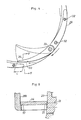
- FIGS 1 and 2 show a turbosupercharger for an engine to which a variable capacity turbine of the present invention is applied.
- This turbosupercharger comprises an overall casing which consists of a compressor casing 1 which defines a scroll passage of a compressor unit, a back plate 2 which covers the back face of the compressor casing 1, a lubrication unit casing 3 which incorporates a structure for lubricating the main shaft of the turbosupercharger, a turbine casing 4 which defines the scroll passage of the turbine unit, and another back plate 23 which covers the back face of the turbine casing 4.
- a scroll passage 5 Inside the compressor casing 1 are defined a scroll passage 5 and an axial passage 6.
- a compressor wheel 7 is provided in a central part of the scroll passage 5 adjacent the internal end of the axial passage 6.
- This compressor wheel 7 is mounted to an end of a main shaft 8 of the turbosupercharger, in such manner as described hereinafter, which is supported in a freely rotatable manner in the center of the lubrication unit casing 3.
- the scroll passage 5 serves as an outlet passage for intake air while the axial passage 6 serves as an inlet passage for intake air as indicated by the arrows in Figure 1.
- the compressor casing 1 and the back plate 2 are integrally attached to each other by means of bolts 10 which are threaded with the outer circumferential portion of the compressor casing 1 by way of a ring member 9.
- the central part of the back plate 2 is provided with a depression which fixedly receives the outer circumferential surface of the lubrication unit casing 3.
- the main shaft 8 is supported as mentioned earlier in a pair of bearing holes 11 and 12 defined in the lubrication unit casing 3 by way of radial bearing metals 13.
- a thrust bearing metal 14 is placed between the back plate 2 and the lubrication unit casing 3, and the support of the main shaft 8 in the thrust direction and the mounting of the compressor wheel 7 on the main shaft 8 are accomplished by fitting a washer 15, a collar 15a which is received in a central hole of the thrust bearing metal 14, a bushing 16 and the compressor wheel 7 onto the main shaft in that order with the washer 15 engaging an annular shoulder formed on the main shaft 8 and by threading a nut 18 on a threaded portion 17 formed on the compressor end of the main shaft 8.
- the collar 15a serves as a spacer for controlling the interposing pressure acting on the thrust bearing metal 14.
- the turbine casing 4 defines therein a scroll passage 21, an inlet opening 21a of the scroll passage 21 which opens in a tangential direction, an outlet passage 22 extending in an axial direction and an outlet opening 22a for this outlet passage 22.
- the directions of the flow of exhaust gas in these passages are indicated by the arrows in Figure 1.
- the back plate 23 is interposed between the turbine casing 4 and the lubrication unit casing 3 at its flange 23a which extends radially from the outer circumferential portion of the back plate 23.
- the connection between the turbine casing 4 and the lubrication unit casing 3 is accomplished by threading nuts 26 with stud bolts 24 provided in the turbine casing 4 by way of a ring member 25 in such a manner that the outer circumferential portion of the lubrication unit casing 3 and the flange 23a of the back plate 23 are held between the outer circumferential portion of the turbine casing 4 and the ring member 25.
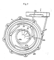
- a fixed vane member 27 for dividing the scroll passage 21 into an outer circumferential passage 21b and an inlet passage 21c is provided in a central portion of the scroll passage 21.
- This fixed vane member 27 comprises a tubular portion 28a provided in a central portion thereof, a disk portion 28b extending radially from the outer circumferential portion of an axially intermediate portion of the tubular portion 28a, and fixed vanes 29 which extend axially from the outer circumferential portion of the disk portion 28b towards the lubrication unit casing 3.
- a turbine wheel 30 integrally mounted on the other end of the main shaft 8 is received in the tubular portion 28a.
- the tubular portion 28a is further fitted into an internal end portion of the outlet passage 22 by way of a pair of metallic seal rings 31 and axial end portions of the fixed vanes 29 are connected to the back plate 23 with bolts 32.
- the internal end of the tubular portion 28a defines a throat or a portion of a locally minimum cross section in cooperation with the back plate 23.
- the outer circumferential portion of the fixed vane member 27 is provided with four of the fixed vanes 29 which surround the turbine wheel 30 in a concentric manner.
- These fixed vanes 29 are arcuate in shape and are arranged at an equal interval along a circumferential direction.
- the gaps between the fixed vanes 29 can be opened and closed with moveable vanes 34 which are each rotatably supported by a pin 33 which is fixedly attached to the corresponding moveable vane 34 and is received in a hole provided in the back plate 23.
- moveable vanes 34 which are arcuate in shape, by having the same curvature as that of the fixed vanes 29 are located. along the same circle as the fixed vanes 29.
- these moveable vanes 34 are pivoted at their portions adjacent the circumferential ends of the corresponding fixed vanes 29 in such a manner that they can only be moved into the interior of the circle.
- the fixed vanes 29 and the corresponding moveable vanes 34 define the leading edges and the trailing edges of four smooth airfoil vanes, respectively, for the fluid flowing through the outer circumferential passage 21b of the scroll passage 21. And, when the moveable vanes 34 are in their fully closed positions, the trailing edges of the airfoils, i.e. the free ends of the moveable vanes 34, slightly overlap the leading edges of the adjacent air foils, i.e. the circumferential ends of the fixed vanes 29, remote from the pins 33, defining a certain gap g min therebetween.
- a shield plate 36 is interposed between the back plate 23 of the turbine unit and the lubrication unit casing 3 and extends towards the rear face of the turbine wheel 30 so as to prevent the heat from the exhaust gas flowing through the exhaust gas turbine unit from being transmitted to the interior of the lubrication unit casing 3. Further, in order to prevent the exhaust gas of the turbine unit from leaking into the interior of the lubrication unit casing 3 a plurality of annular grooves 38 serving as a labyrinth seal are formed around the portion of the main shaft 8 which is passed through a central hole 37 of the lubrication unit casing 3.
- the upper end of the lubrication unit casing 3, in the sense of Figure 1, is provided with a lubrication inlet hole 40 for introducing lubrication oil supplied from a lubrication oil pump, which is not shown in the drawings, to the radial bearing metals 13 and the thrust bearing metal 14 by way of a lubrication oil passage 41 formed in the interior of the lubrication unit casing 3.
- the lubrication oil which is ejected from each lubricated part is led out from a lubrication oil outlet 42 which is defined in the lubrication unit casing 3 and is then collected in an oil sump which is also not shown in the drawings.
- the outer circumferential surface of the bushing 16 passes through a central hole 44 of the back plate 2 by way of a seal ring 43 and a guide plate 45 having a central hole receiving the bushing 16 therethrough is interposed between the back plate 2 and the thrust bearing metal 14.
- the lower portion of this guide plate 45 is curved away from the compressor unit.
- the lubrication oil which has flowed out from the thrust bearing metal 14 is thrown off from the outer circumferential surface of the bushing 16 by centrifugal force and is received by the guide plate 45 to be ultimately returned to the oil sump.
- the turbine unit of a turbosupercharger of this type can reach a substantially high temperature during its operation and control of the clearance on either side edge of each moveable vane 34 and possibility of mechanical seizure of the moveable vanes 34 due to uneven thermal expansion could be a problem.
- the moveable vanes 34 rotate in a gap defined between the back plate 23 and the disk portion 28b of the fixed vane member 27 which is a separate body from the turbine casing 4, the control of the gap for the moveable vanes 34 can be favorably accomplished.
- the connection between the back plate 23 and the fixed vane member 27 is highly rigid and the management and control of the clearance in the range of the motion of the moveable vanes 34 can be favorably accomplished.
- the width of the gap defined between the back plate 23 and the disk portion 28b for accommodating the moveable vanes 34 in a freely rotatable manner is a at the outer periphery and b at the inner periphery (a ⁇ b) or, in other words, flares out from the outer periphery to the inner periphery, the tendency for the inner peripheral portion to deform inwardly due to thermal expansion can be compensated for and the mechanical seizure of the moveable vanes 34 can be avoided.
- the opening degree of the moveable vanes 34 is at a minimum or, in other words, when the width of the gap between the moveable vanes 34 and the fixed vanes 29 is reduced to g min , the leakage of the exhaust gas from the axial end surfaces of the moveable vanes 34 could be a problem.
- the axial dimension of the part which receives each of the moveable vanes can be accurately determined because the fixed vane member 27 is attached to the back plate 23 at its fixed vanes 29 and the leakage of exhaust gas from the axial end surfaces of the moveable vanes 34 can be limited to a relatively low level.
- shoulders 5l and 50 are provided in the back plate 23 and the opposing surface of the disk portion 28b of the fixed vane member 27, as best shown in Figures 3 and 5, so as to be complementary to the axial ends of the moveable vanes 34 as best shown in Figure 5, the leakage of exhaust gas from the axial end portions of the moveable vanes 34 is minimized and the efficiency of the turbine can be favorably improved.
- the length of the overlap L between the leading edge of each fixed vane and the trailing edge of the adjacent moveable vane strongly affects the performance of the turbine. For instance, if the overlap L along the direction of the fluid flow is excessive, the resistance to the fluid flow becomes so great that not only the fluid flow efficiency drops but also an aerodynamic lift acting upon the moveable vanes could impair the precision of control. On the other hand, if the overlap L is too small, the smoothing of the fluid flow tends to be insufficient and this also causes reduction in the fluid flow efficiency.
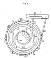
- Figures 6 to 8 show different embodiments of the present invention and those parts corresponding to those of the previous embodiment are denoted by like numerals.
- each moveable vane 34 is associated with a different one of the fixed vanes 29 and defines a substantially smooth airfoil with the fixed vane 29.
- the circumferential positions of the moveable and fixed vanes can be freely selected but it is preferred that one of the moveable vanes aligns with the inlet opening 21a of the scroll passage 21 as exemplified by the embodiments shown in Figures 7 and 8. This latter feature is advantageous in reducing the flow resistance to the gas introduced into the turbine and is of a greater significant when there are a fewer number of vanes.
- the present invention can contribute to the improvement of turbine efficiency and improvement of engine performance when the invention is applied to a turbosupercharger for the engine.
- the control and management of the clearance of the moveable vanes are simplified with the result that a significant advantage can be obtained in improving the facility of manufacture and the reliability of the turbine. And, since the clearance of the moveable vanes when the opening degree of the variable nozzles is at a minimum value is minimized, the efficiency of the turbine can be improved.
- the present invention provides a variable capacity turbine which can operate even when the flow rate of the fluid entering the turbine is small and, yet, allows the passage of the fluid flow without involving a significant pressure drop when the flow rate of the fluid entering the turbine has increased; and furthermore provides a variable capacity turbine which allows a wide range of variation without increasing the resistance loss of the fluid; and furthermore provides a variable capacity turbine which is capable of controlling the entry velocity of fluid into the turbine wheel with a high level of reliability even in a high temperature environment; and furthermore provides a variable capacity turbine in which the clearance of the side edges of the moveable vanes is minimized when the opening of the variable nozzles is small so as to improve the efficiency of the turbine; and furthermore provides a variable capacity turbine which is free from the mechanical seizure of the moving parts of the turbine.
Landscapes
- Engineering & Computer Science (AREA)
- Mechanical Engineering (AREA)
- General Engineering & Computer Science (AREA)
- Supercharger (AREA)
- Control Of Turbines (AREA)
Applications Claiming Priority (6)
| Application Number | Priority Date | Filing Date | Title |
|---|---|---|---|
| JP61124996A JPS62282122A (ja) | 1986-05-30 | 1986-05-30 | 可変容量タ−ビン |
| JP61124997A JPS62282123A (ja) | 1986-05-30 | 1986-05-30 | タ−ビンの可変ノズル構造 |
| JP124997/86 | 1986-05-30 | ||
| JP61124998A JPS62282124A (ja) | 1986-05-30 | 1986-05-30 | タ−ビンの可変ノズル構造 |
| JP124996/86 | 1986-05-30 | ||
| JP124998/86 | 1986-05-30 |
Publications (3)
| Publication Number | Publication Date |
|---|---|
| EP0248624A2 true EP0248624A2 (de) | 1987-12-09 |
| EP0248624A3 EP0248624A3 (en) | 1989-05-03 |
| EP0248624B1 EP0248624B1 (de) | 1992-04-15 |
Family
ID=27315019
Family Applications (1)
| Application Number | Title | Priority Date | Filing Date |
|---|---|---|---|
| EP87304832A Expired - Lifetime EP0248624B1 (de) | 1986-05-30 | 1987-06-01 | Turbine mit variablem Schluckvermögen |
Country Status (4)
| Country | Link |
|---|---|
| US (1) | US4880351A (de) |
| EP (1) | EP0248624B1 (de) |
| CA (1) | CA1279265C (de) |
| DE (1) | DE3778209D1 (de) |
Cited By (10)
| Publication number | Priority date | Publication date | Assignee | Title |
|---|---|---|---|---|
| EP0332354A1 (de) * | 1988-03-08 | 1989-09-13 | Honda Giken Kogyo Kabushiki Kaisha | Turbine mit Verstelleinrichtung |
| GB2295650A (en) * | 1994-11-30 | 1996-06-05 | Sovereign Surgical Ltd | Air deflector for peak-flow meter |
| WO2002012770A1 (de) | 2000-08-07 | 2002-02-14 | Abb Turbo Systems Ag | Verbindungsvorrichtung für gehäuseteile von turboladern |
| FR2845731A1 (fr) * | 2002-10-14 | 2004-04-16 | Renault Sa | Turbocompresseur a insert double jeu pour vehicule automobile |
| EP2098703A1 (de) * | 2008-03-06 | 2009-09-09 | Honeywell International Inc. | Turboladeranordnung mit Wärmeschildzentrieranordnungen |
| EP1691034A3 (de) * | 2005-02-10 | 2012-04-11 | Mitsubishi Heavy Industries, Ltd. | Turbolader mit variabler Geometrie und Verfahren zur Herstellung |
| EP2868894A1 (de) * | 2013-10-30 | 2015-05-06 | Hyundai Motor Company | Turbosystem mit variabler Geometrie |
| US9556880B2 (en) | 2013-06-26 | 2017-01-31 | Honeywell International Inc. | Turbine exhaust seal |
| WO2020049255A1 (fr) * | 2018-09-06 | 2020-03-12 | Liebherr-Aerospace Toulouse Sas | Distributeur d'une turbine radiale de turbomachine, turbomachine comprenant un tel distributeur et système de conditionnement d'air comprenant une telle turbomachine |
| CN116241337A (zh) * | 2021-12-29 | 2023-06-09 | 盖瑞特动力科技(上海)有限公司 | 涡轮增压器涡轮机组件 |
Families Citing this family (14)
| Publication number | Priority date | Publication date | Assignee | Title |
|---|---|---|---|---|
| US5028208A (en) * | 1989-01-10 | 1991-07-02 | Ishikawajima-Harima Jukogyo Kabushiki Kaisha | Nozzle blade angle adjustment device for variable geometry turbocharger |
| US5299909A (en) * | 1993-03-25 | 1994-04-05 | Praxair Technology, Inc. | Radial turbine nozzle vane |
| JP2001289050A (ja) * | 1999-05-20 | 2001-10-19 | Hitachi Ltd | 可変容量ターボ過給機 |
| DE19929946C2 (de) * | 1999-06-29 | 2001-05-10 | Daimler Chrysler Ag | Abgasturbolader zur Einstellung der Verbrennungsluftmenge für eine Brennkraftmaschine |
| GB0218092D0 (en) * | 2002-08-03 | 2002-09-11 | Holset Engineering Co | Turbocharger |
| GB0407978D0 (en) * | 2004-04-08 | 2004-05-12 | Holset Engineering Co | Variable geometry turbine |
| GB2426555A (en) * | 2005-05-28 | 2006-11-29 | Siemens Ind Turbomachinery Ltd | Turbocharger air intake |
| JP2010531957A (ja) * | 2007-06-26 | 2010-09-30 | ボーグワーナー・インコーポレーテッド | 可変容量ターボチャージャ |
| US8056336B2 (en) * | 2008-05-05 | 2011-11-15 | Honeywell International Inc. | Turbocharger with variable nozzle having vane sealing surfaces |
| KR101021658B1 (ko) | 2008-08-12 | 2011-03-17 | (주)계양정밀 | 가변노즐장치를 구비한 터보차져 |
| JP2013104412A (ja) * | 2011-11-16 | 2013-05-30 | Toyota Motor Corp | 可変ノズル機構 |
| JP5916377B2 (ja) * | 2011-12-27 | 2016-05-11 | 三菱重工業株式会社 | 過給機用タービン及び過給機の組立方法 |
| US9932888B2 (en) * | 2016-03-24 | 2018-04-03 | Borgwarner Inc. | Variable geometry turbocharger |
| WO2019030892A1 (ja) * | 2017-08-10 | 2019-02-14 | 三菱重工エンジン&ターボチャージャ株式会社 | ターボチャージャ用タービン及びターボチャージャ |
Family Cites Families (25)
| Publication number | Priority date | Publication date | Assignee | Title |
|---|---|---|---|---|
| CH127459A (de) * | 1922-11-07 | 1928-09-01 | Escher Wyss Maschf Ag | Leitrad für Kreiselpumpen. |
| CH102824A (de) * | 1922-11-07 | 1924-01-02 | Escher Wyss Maschf Ag | Leitrad für Kreiselpumpen. |
| CH129731A (de) * | 1927-09-10 | 1929-01-02 | Alfred Dr Med Schoenlank | Inhalationsapparat mit Einrichtung zur Dampferzeugung. |
| US2428830A (en) * | 1942-04-18 | 1947-10-14 | Turbo Engineering Corp | Regulation of combustion gas turbines arranged in series |
| US2382913A (en) * | 1943-04-12 | 1945-08-14 | Gen Electric | Centrifugal compressor |
| US2648195A (en) * | 1945-12-28 | 1953-08-11 | Rolls Royce | Centrifugal compressor for supercharging internal-combustion engines |
| US2671635A (en) * | 1950-05-25 | 1954-03-09 | Baldwin Lima Hamilton Corp | Reversible pump-turbine |
| US2895295A (en) * | 1952-04-04 | 1959-07-21 | Solar Aircraft Co | Variable speed gas turbine |
| US2860827A (en) * | 1953-06-08 | 1958-11-18 | Garrett Corp | Turbosupercharger |
| US2895925A (en) * | 1956-02-02 | 1959-07-21 | Rohm & Haas | Anion-exchange resin containing sulfonium groups |
| US3101926A (en) * | 1960-09-01 | 1963-08-27 | Garrett Corp | Variable area nozzle device |
| CH422214A (de) * | 1964-10-01 | 1966-10-15 | Escher Wyss Ag | Verstellvorrichtung für einen Kranz von um zur Kranzachse parallele Achsen schwenkbaren Schaufeln |
| US3442493A (en) * | 1965-10-22 | 1969-05-06 | Gen Electric | Articulated airfoil vanes |
| US3313518A (en) * | 1966-02-25 | 1967-04-11 | Garrett Corp | Turbine control |
| DE1952423A1 (de) * | 1969-10-17 | 1971-05-27 | Garrett Corp | Schaufeldichtung |
| SU383894A1 (ru) * | 1972-03-21 | 1973-05-23 | Рабочее колесо центробежного вентилятора | |
| SE7801452L (sv) * | 1977-05-04 | 1978-11-05 | Wallace Murray Corp | Forfarande for drivning av en turbin |
| SU715812A1 (ru) * | 1978-02-20 | 1980-02-15 | Предприятие П/Я А-1665 | Регулируемый сопловой аппарат центростремительной турбины |
| US4232992A (en) * | 1978-10-23 | 1980-11-11 | Possell Clarence R | Geothermal turbine and method of using the same |
| US4678397A (en) * | 1983-06-15 | 1987-07-07 | Nissan Motor Co., Ltd. | Variable-capacitance radial turbine having swingable tongue member |
| JPS61126052U (de) * | 1985-01-29 | 1986-08-07 | ||
| DE3516738A1 (de) * | 1985-05-09 | 1986-11-13 | Mtu Motoren- Und Turbinen-Union Friedrichshafen Gmbh, 7990 Friedrichshafen | Stroemungsmaschine |
| DE3541508C1 (de) * | 1985-11-23 | 1987-02-05 | Kuehnle Kopp Kausch Ag | Abgasturbolader |
| JPS62282126A (ja) * | 1986-05-30 | 1987-12-08 | Honda Motor Co Ltd | タ−ビンの可変ノズル構造 |
| JPH0211822A (ja) * | 1988-06-29 | 1990-01-16 | Isuzu Motors Ltd | 回転電機付ターボチャージャの駆動装置 |
-
1987
- 1987-05-27 US US07/054,499 patent/US4880351A/en not_active Expired - Fee Related
- 1987-05-29 CA CA000538343A patent/CA1279265C/en not_active Expired - Lifetime
- 1987-06-01 DE DE8787304832T patent/DE3778209D1/de not_active Expired - Lifetime
- 1987-06-01 EP EP87304832A patent/EP0248624B1/de not_active Expired - Lifetime
Cited By (18)
| Publication number | Priority date | Publication date | Assignee | Title |
|---|---|---|---|---|
| EP0332354A1 (de) * | 1988-03-08 | 1989-09-13 | Honda Giken Kogyo Kabushiki Kaisha | Turbine mit Verstelleinrichtung |
| GB2295650A (en) * | 1994-11-30 | 1996-06-05 | Sovereign Surgical Ltd | Air deflector for peak-flow meter |
| GB2295650B (en) * | 1994-11-30 | 1998-10-28 | Sovereign Surgical Ltd | Peak flow meter |
| WO2002012770A1 (de) | 2000-08-07 | 2002-02-14 | Abb Turbo Systems Ag | Verbindungsvorrichtung für gehäuseteile von turboladern |
| FR2845731A1 (fr) * | 2002-10-14 | 2004-04-16 | Renault Sa | Turbocompresseur a insert double jeu pour vehicule automobile |
| WO2004036010A3 (fr) * | 2002-10-14 | 2004-06-10 | Renault Sa | Turbocompresseur a insert double jeu pour les aubes de guidage |
| EP1691034A3 (de) * | 2005-02-10 | 2012-04-11 | Mitsubishi Heavy Industries, Ltd. | Turbolader mit variabler Geometrie und Verfahren zur Herstellung |
| US8092162B2 (en) | 2008-03-06 | 2012-01-10 | Honeywell International Inc. | Turbocharger assembly having heat shield-centering arrangements |
| EP2098703A1 (de) * | 2008-03-06 | 2009-09-09 | Honeywell International Inc. | Turboladeranordnung mit Wärmeschildzentrieranordnungen |
| US8353666B2 (en) | 2008-03-06 | 2013-01-15 | Honeywell International Inc. | Turbocharger assembly having heat shield-centering arrangements |
| US9556880B2 (en) | 2013-06-26 | 2017-01-31 | Honeywell International Inc. | Turbine exhaust seal |
| EP2868894A1 (de) * | 2013-10-30 | 2015-05-06 | Hyundai Motor Company | Turbosystem mit variabler Geometrie |
| US9689275B2 (en) | 2013-10-30 | 2017-06-27 | Hyundai Motor Company | Variable geometry turbo system |
| WO2020049255A1 (fr) * | 2018-09-06 | 2020-03-12 | Liebherr-Aerospace Toulouse Sas | Distributeur d'une turbine radiale de turbomachine, turbomachine comprenant un tel distributeur et système de conditionnement d'air comprenant une telle turbomachine |
| FR3085720A1 (fr) * | 2018-09-06 | 2020-03-13 | Liebherr-Aerospace Toulouse Sas | Distributeur d'une turbine radiale de turbomachine, turbomachine comprenant un tel distributeur et systeme de conditionnement d'air comprenant une telle turbomachine |
| CN116241337A (zh) * | 2021-12-29 | 2023-06-09 | 盖瑞特动力科技(上海)有限公司 | 涡轮增压器涡轮机组件 |
| EP4206442A1 (de) * | 2021-12-29 | 2023-07-05 | Garrett Transportation I Inc. | Turboladerturbinenanordnung |
| US11821357B2 (en) | 2021-12-29 | 2023-11-21 | Garrett Transportation I Inc. | Turbocharger turbine assembly |
Also Published As
| Publication number | Publication date |
|---|---|
| EP0248624B1 (de) | 1992-04-15 |
| EP0248624A3 (en) | 1989-05-03 |
| DE3778209D1 (de) | 1992-05-21 |
| US4880351A (en) | 1989-11-14 |
| CA1279265C (en) | 1991-01-22 |
Similar Documents
| Publication | Publication Date | Title |
|---|---|---|
| EP0248624B1 (de) | Turbine mit variablem Schluckvermögen | |
| US5372485A (en) | Exhaust-gas turbocharger with divided, variable guide vanes | |
| EP0247905B1 (de) | Leitschaufelverstelleinrichtung | |
| US4679984A (en) | Actuation system for variable nozzle turbine | |
| US4804316A (en) | Suspension for the pivoting vane actuation mechanism of a variable nozzle turbocharger | |
| US5758500A (en) | Exhaust gas turbochanger for an internal combustion engine | |
| US5454225A (en) | Exhaust gas turbocharger for an internal combustion engine | |
| CN1118638C (zh) | 用于内燃机的涡轮增压器 | |
| US4986733A (en) | Turbocharger compressor wheel assembly with boreless hub compressor wheel | |
| US5857337A (en) | Turbocharger | |
| US4776168A (en) | Variable geometry turbocharger turbine | |
| US4654941A (en) | Method of assembling a variable nozzle turbocharger | |
| US5176497A (en) | Boreless hub compressor wheel assembly for a turbocharger | |
| CN1454285A (zh) | 带有滑动活塞的可变形状涡轮增压器 | |
| EP3043073B1 (de) | Mehrstufige radialverdichterablenkplatte | |
| EP0131736B1 (de) | Axialturbine für Abgasturbolader | |
| US3972644A (en) | Vane control arrangement for variable area turbine nozzle | |
| JP2017515051A (ja) | 可変ジオメトリタービンアセンブリ | |
| EP0332354A1 (de) | Turbine mit Verstelleinrichtung | |
| US4684319A (en) | Turbocharger with variable nozzle mechanism | |
| US4624629A (en) | Lubrication mechanism for a turbocharger | |
| EP3795810B1 (de) | Turboladerturbinenrad | |
| JPS61268804A (ja) | 可変タ−ビンノズル式過給機 | |
| EP4191022B1 (de) | Turboladerturbinenrad | |
| JP2002070568A (ja) | 排気タービン過給機 |
Legal Events
| Date | Code | Title | Description |
|---|---|---|---|
| PUAI | Public reference made under article 153(3) epc to a published international application that has entered the european phase |
Free format text: ORIGINAL CODE: 0009012 |
|
| AK | Designated contracting states |
Kind code of ref document: A2 Designated state(s): DE FR GB IT |
|
| PUAL | Search report despatched |
Free format text: ORIGINAL CODE: 0009013 |
|
| AK | Designated contracting states |
Kind code of ref document: A3 Designated state(s): DE FR GB IT |
|
| 17P | Request for examination filed |
Effective date: 19890516 |
|
| 17Q | First examination report despatched |
Effective date: 19890915 |
|
| GRAA | (expected) grant |
Free format text: ORIGINAL CODE: 0009210 |
|
| AK | Designated contracting states |
Kind code of ref document: B1 Designated state(s): DE FR GB IT |
|
| REF | Corresponds to: |
Ref document number: 3778209 Country of ref document: DE Date of ref document: 19920521 |
|
| ET | Fr: translation filed | ||
| ITF | It: translation for a ep patent filed | ||
| PLBE | No opposition filed within time limit |
Free format text: ORIGINAL CODE: 0009261 |
|
| STAA | Information on the status of an ep patent application or granted ep patent |
Free format text: STATUS: NO OPPOSITION FILED WITHIN TIME LIMIT |
|
| 26N | No opposition filed | ||
| PGFP | Annual fee paid to national office [announced via postgrant information from national office to epo] |
Ref country code: FR Payment date: 19990610 Year of fee payment: 13 |
|
| PG25 | Lapsed in a contracting state [announced via postgrant information from national office to epo] |
Ref country code: FR Free format text: LAPSE BECAUSE OF NON-PAYMENT OF DUE FEES Effective date: 20010228 |
|
| REG | Reference to a national code |
Ref country code: FR Ref legal event code: ST |
|
| REG | Reference to a national code |
Ref country code: GB Ref legal event code: IF02 |
|
| PGFP | Annual fee paid to national office [announced via postgrant information from national office to epo] |
Ref country code: DE Payment date: 20050526 Year of fee payment: 19 |
|
| PG25 | Lapsed in a contracting state [announced via postgrant information from national office to epo] |
Ref country code: IT Free format text: LAPSE BECAUSE OF NON-PAYMENT OF DUE FEES;WARNING: LAPSES OF ITALIAN PATENTS WITH EFFECTIVE DATE BEFORE 2007 MAY HAVE OCCURRED AT ANY TIME BEFORE 2007. THE CORRECT EFFECTIVE DATE MAY BE DIFFERENT FROM THE ONE RECORDED. Effective date: 20050601 |
|
| PGFP | Annual fee paid to national office [announced via postgrant information from national office to epo] |
Ref country code: GB Payment date: 20050601 Year of fee payment: 19 |
|
| PG25 | Lapsed in a contracting state [announced via postgrant information from national office to epo] |
Ref country code: GB Free format text: LAPSE BECAUSE OF NON-PAYMENT OF DUE FEES Effective date: 20060601 |
|
| PG25 | Lapsed in a contracting state [announced via postgrant information from national office to epo] |
Ref country code: DE Free format text: LAPSE BECAUSE OF NON-PAYMENT OF DUE FEES Effective date: 20070103 |
|
| GBPC | Gb: european patent ceased through non-payment of renewal fee |
Effective date: 20060601 |