EP0247930B1 - Wrist spindle set for a laser beam welding machine - Google Patents
Wrist spindle set for a laser beam welding machine Download PDFInfo
- Publication number
- EP0247930B1 EP0247930B1 EP87401152A EP87401152A EP0247930B1 EP 0247930 B1 EP0247930 B1 EP 0247930B1 EP 87401152 A EP87401152 A EP 87401152A EP 87401152 A EP87401152 A EP 87401152A EP 0247930 B1 EP0247930 B1 EP 0247930B1
- Authority
- EP
- European Patent Office
- Prior art keywords
- laser beam
- axis
- spindle
- laser
- wrist joint
- Prior art date
- Legal status (The legal status is an assumption and is not a legal conclusion. Google has not performed a legal analysis and makes no representation as to the accuracy of the status listed.)
- Expired - Lifetime
Links
Images
Classifications
-
- B—PERFORMING OPERATIONS; TRANSPORTING
- B23—MACHINE TOOLS; METAL-WORKING NOT OTHERWISE PROVIDED FOR
- B23K—SOLDERING OR UNSOLDERING; WELDING; CLADDING OR PLATING BY SOLDERING OR WELDING; CUTTING BY APPLYING HEAT LOCALLY, e.g. FLAME CUTTING; WORKING BY LASER BEAM
- B23K26/00—Working by laser beam, e.g. welding, cutting or boring
- B23K26/08—Devices involving relative movement between laser beam and workpiece
- B23K26/0869—Devices involving movement of the laser head in at least one axial direction
- B23K26/0876—Devices involving movement of the laser head in at least one axial direction in at least two axial directions
- B23K26/0884—Devices involving movement of the laser head in at least one axial direction in at least two axial directions in at least three axial directions, e.g. manipulators, robots
-
- B—PERFORMING OPERATIONS; TRANSPORTING
- B23—MACHINE TOOLS; METAL-WORKING NOT OTHERWISE PROVIDED FOR
- B23K—SOLDERING OR UNSOLDERING; WELDING; CLADDING OR PLATING BY SOLDERING OR WELDING; CUTTING BY APPLYING HEAT LOCALLY, e.g. FLAME CUTTING; WORKING BY LASER BEAM
- B23K26/00—Working by laser beam, e.g. welding, cutting or boring
- B23K26/02—Positioning or observing the workpiece, e.g. with respect to the point of impact; Aligning, aiming or focusing the laser beam
- B23K26/04—Automatically aligning, aiming or focusing the laser beam, e.g. using the back-scattered light
-
- B—PERFORMING OPERATIONS; TRANSPORTING
- B23—MACHINE TOOLS; METAL-WORKING NOT OTHERWISE PROVIDED FOR
- B23Q—DETAILS, COMPONENTS, OR ACCESSORIES FOR MACHINE TOOLS, e.g. ARRANGEMENTS FOR COPYING OR CONTROLLING; MACHINE TOOLS IN GENERAL CHARACTERISED BY THE CONSTRUCTION OF PARTICULAR DETAILS OR COMPONENTS; COMBINATIONS OR ASSOCIATIONS OF METAL-WORKING MACHINES, NOT DIRECTED TO A PARTICULAR RESULT
- B23Q17/00—Arrangements for observing, indicating or measuring on machine tools
- B23Q17/22—Arrangements for observing, indicating or measuring on machine tools for indicating or measuring existing or desired position of tool or work
- B23Q17/2233—Arrangements for observing, indicating or measuring on machine tools for indicating or measuring existing or desired position of tool or work for adjusting the tool relative to the workpiece
Definitions
- the present invention relates to a laser beam cutting and welding machine as described in the preamble of the claim.
- a laser beam cutting and welding machine is known from document EP-A1-0163207.
- the invention proposes to improve the machine devolved in this document.
- said sensor is a measuring probe, and that said probe is mounted in the axis of the laser nozzle opposite the laser nozzle relative to the axis of rotation of said nozzle.
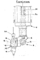
- This figure shows a laser wrist 2 surmounted by a spindle 4 of a vertical translation unit not shown for a five-axis laser cutting and welding machine.
- This wrist has a body 6 capable of rotating around the fourth axis 8, and an end portion 10 capable of rotating around the fifth axis 12.
- the body 6 is provided with a mirror 14.
- the end part 10 comprises a mirror 16, a laser nozzle 18 and a measuring probe 20.
- This measuring probe is fixed on the support 22 of this laser nozzle 18 and of this mirror 16, opposite to this nozzle and in the axis thereof.
- the spindle 4 is crossed by an axial bore 24 whose cross section is determined so as to allow a laser beam 26 of high power to pass with a device for bending the latter such as a mirror.
- This laser beam comes from a laser radiation generator outside the machine; it crosses spindle 4 after a journey inside, for example, structural profiles.
- An automatic operating cycle includes, for example, the following steps:
Landscapes
- Engineering & Computer Science (AREA)
- Physics & Mathematics (AREA)
- Optics & Photonics (AREA)
- Mechanical Engineering (AREA)
- Plasma & Fusion (AREA)
- Robotics (AREA)
- Laser Beam Processing (AREA)
- Manipulator (AREA)
- Length Measuring Devices By Optical Means (AREA)
Description
La présente invention se rapport à une machine de découpe et de soudage par faisceau laser telle que décrite dans le préamble de la revendication. Une telle machine est connue du document EP-A1-0163207.The present invention relates to a laser beam cutting and welding machine as described in the preamble of the claim. Such a machine is known from document EP-A1-0163207.
L'invention se propose d'améliorer la machine dévoltée dans ce document.The invention proposes to improve the machine devolved in this document.
A cet effet, elle est caractérisée par le fait que ledit capteur est un palpeur de mesure, et que ledit palpeur est monté dans l'axe de la buse laser à l'opposé de la buse laser par rapport à l'axe de rotation de ladite buse.To this end, it is characterized by the fact that said sensor is a measuring probe, and that said probe is mounted in the axis of the laser nozzle opposite the laser nozzle relative to the axis of rotation of said nozzle.
Grâce à l'introduction de la fonction additionnelle de palpage, un cycle automatique de travail sans aucune intervention manuelle peut être aisément programmé. Un guidage simple et efficace d'un faisceau laser de grande puissance est obtenue au moyen de cette broche creuse.Thanks to the introduction of the additional probing function, an automatic work cycle without any manual intervention can be easily programmed. Simple and efficient guidance of a high power laser beam is obtained by means of this hollow spindle.
D'autres particularités et avantages apparoît- ront plus clairement à la lecture de la description qui suit d'un mode de réalisation préféré, donné à titre d'exemple non limitatif, en référence à la figure unique annexée qui représente schématiquement un ensemble poignet-broche conforme à l'invention.Other features and advantages will appear more clearly on reading the following description of a preferred embodiment, given by way of nonlimiting example, with reference to the single appended figure which schematically represents a wrist- spindle according to the invention.
Cette figure montre un poignet laser 2 surmonté d'une broche 4 d'une unité de translation verticale non représentée pour une machine cinq axes de découpe et de soudage laser.This figure shows a
Ce poignet comporte un corps 6 susceptible de tourner autour du quatrième axe 8, et une partie d'extrémité 10 susceptible de tourner autour du cinquième axe 12.This wrist has a
Le corps 6 est pourvu d'un miroir 14. La partie d'extrémité 10 comporte un miroir 16, une buse de laser 18 et un palpeur de mesure 20.The
Ce palpeur de mesure est fixé sur le support 22 de cette buse de laser 18 et de ce miroir 16, à l'opposé de cette buse et dans l'axe de celui-ci.This measuring probe is fixed on the
La broche 4 est traversée par un alésage axial 24 dont la section droite est déterminée de manière à laisser passer un faisceau laser 26 de puissance élévée avec un dispositif de coudage de celui-ci tel qu'un miroir. Ce faisceau laser provient d'un générateur de rayonnement laser extérieur à la machine; il traverse la broche 4 après un parcours à l'intérieur par exemple de profilés de structure.The
Un cycle automatique de fonctionnement comprend par exemple les étapes suivantes:An automatic operating cycle includes, for example, the following steps:
un premier mouvement de rotation de 180° autour du cinquème axe 12, appliqué à la partie d'extrémité 10 du poignet laser 2;a first 180 ° rotational movement around the
une opération programmée de palpage de la pièce ou de son support au moyen du palpeur intégré 20 afin de localiser cette pièce ou ce support dans le volume de travail de la machine; un changement de repère est ainsi obtenu pour le programme de découpe ou de soudage (gestion par ordinateur);a programmed operation of probing the part or its support by means of the integrated
un second mouvement de rotation de 180° autour du cinquième axe 12 pour présenter la buse de laser 18 devant la pièce;a second 180 ° rotational movement around the
une exécution du programme de découpe ou de soudage;execution of the cutting or welding program;
un troisième mouvement de rotation de 180° autour du cinquième axe 12 pour effectuer avec la palpeur intégré 20, un contrôle dimensionnel de toutes les phases opératoires réalisées du programme de découpe ou de soudage.a third 180 ° rotational movement around the
Claims (1)
- A wrist joint-spindle assembly for a laser beam cutting and welding machine comprising a spindle (4) having an axial bore (24) with an axis (8) of a cross-section sufficient to permit the passage of a high-power laser beam (26) and, at the end of the spindle (4), a wrist joint (2) with two concurrent axes of rotation (8, 12), the wrist joint incorporating two mirrors (14, 16) permitting double diversion of the laser beam, the two mirrors (14, 16) being associated on the one hand with the spindle (4) and on the other hand with a laser tip (18) which can turn at the end of the wrist joint (2) about the axis of rotation (12), a measuring pick-up being associated with the wrist joint-spindle assembly, characterised in that said pick-up (20) is a measuring feeler and that said feeler is mounted on the axis of the laser tip (18) in opposite relationship to the laser tip (18) with respect to the axis of rotation (12) of said tip (18).
Applications Claiming Priority (2)
| Application Number | Priority Date | Filing Date | Title |
|---|---|---|---|
| FR8607537A FR2599287B1 (en) | 1986-05-27 | 1986-05-27 | WRIST-PIN ASSEMBLY FOR LASER BEAM CUTTING AND WELDING MACHINE. |
| FR8607537 | 1986-05-27 |
Publications (2)
| Publication Number | Publication Date |
|---|---|
| EP0247930A1 EP0247930A1 (en) | 1987-12-02 |
| EP0247930B1 true EP0247930B1 (en) | 1990-11-28 |
Family
ID=9335666
Family Applications (1)
| Application Number | Title | Priority Date | Filing Date |
|---|---|---|---|
| EP87401152A Expired - Lifetime EP0247930B1 (en) | 1986-05-27 | 1987-05-22 | Wrist spindle set for a laser beam welding machine |
Country Status (4)
| Country | Link |
|---|---|
| EP (1) | EP0247930B1 (en) |
| DE (1) | DE3766417D1 (en) |
| ES (1) | ES2019107B3 (en) |
| FR (1) | FR2599287B1 (en) |
Families Citing this family (5)
| Publication number | Priority date | Publication date | Assignee | Title |
|---|---|---|---|---|
| DE59002563D1 (en) * | 1990-01-20 | 1993-10-07 | Thyssen Industrie | Method and device for welding steel sheets together using laser beam welding. |
| DE4025851A1 (en) * | 1990-08-16 | 1992-02-20 | Messerschmitt Boelkow Blohm | DEVICE FOR MEASURING REFLECTED RADIATION |
| DE4306282A1 (en) * | 1993-03-01 | 1994-09-15 | Emhart Inc | Method and device for welding a weld-in part in a welding point comprising a metal plate and an overlying metal support |
| CN111730210B (en) * | 2020-06-09 | 2022-01-18 | 匠铜实业(杭州)有限公司 | Double-spindle laser engraving machine adopting polar coordinate motion |
| CN118848116B (en) * | 2024-06-07 | 2026-01-20 | 中国长江电力股份有限公司 | GIL pipeline automatic punching equipment and automatic punching method |
Family Cites Families (1)
| Publication number | Priority date | Publication date | Assignee | Title |
|---|---|---|---|---|
| IT1179924B (en) * | 1984-05-22 | 1987-09-16 | Prima Progetti Spa | HEAD FOCUSING MACHINE FOR A LASER BEAM CUTTING MACHINE |
-
1986
- 1986-05-27 FR FR8607537A patent/FR2599287B1/en not_active Expired
-
1987
- 1987-05-22 DE DE8787401152T patent/DE3766417D1/en not_active Expired - Fee Related
- 1987-05-22 EP EP87401152A patent/EP0247930B1/en not_active Expired - Lifetime
- 1987-05-22 ES ES87401152T patent/ES2019107B3/en not_active Expired - Lifetime
Also Published As
| Publication number | Publication date |
|---|---|
| DE3766417D1 (en) | 1991-01-10 |
| FR2599287A1 (en) | 1987-12-04 |
| EP0247930A1 (en) | 1987-12-02 |
| FR2599287B1 (en) | 1988-10-07 |
| ES2019107B3 (en) | 1991-06-01 |
Similar Documents
| Publication | Publication Date | Title |
|---|---|---|
| CA2028351A1 (en) | Touch up tooling for turbine engine rotor blades and process using same | |
| EP0247930B1 (en) | Wrist spindle set for a laser beam welding machine | |
| EP1310314A1 (en) | Tool, Machine and Procedure for the Orbital Drilling of a Hole | |
| JPH1199403A (en) | Spindle device | |
| EP0700795A1 (en) | Device for marking, to get identification signs in two dimensions on the surface of an object | |
| EP0436453A1 (en) | Tool-unit with sensing device | |
| FR2534515A1 (en) | Vibrating tool holder drive by flexible shaft | |
| FR2528373A1 (en) | STEERING DEVICE OF A VEHICLE WITH WHEELS FRONT AND REAR GUIDELINES | |
| EP1252967B1 (en) | Spindle structure | |
| FR2640538A1 (en) | MACHINE TOOL FOR RECTIFYING THE HELICOIDAL GROOVES OF A CUTTING TOOL | |
| EP3307462B1 (en) | Lathe and guide bushing | |
| EP0684170B1 (en) | Wiper module for a motor vehicle window | |
| FR2707198A1 (en) | Lubrication system for a tool holder. | |
| EP0554629B1 (en) | Honing machine with expansible tool | |
| FR2829952A1 (en) | Pneumatic stamping press for aeronautical components has pair of drive couplings between motor and output shaft to drive tool carrying spindle | |
| CH630830A5 (en) | CONTROL MECHANISM OF THE TOOL HOLDER OF A TRANSFER MACHINE. | |
| EP1314501A1 (en) | Boring head with tool feed independant from the rotation | |
| FR2496516A1 (en) | Rocking head for milling machine - is mounted in rotary housing containing concentric drive shaft coaxial with milling spindle | |
| WO1992021455A1 (en) | Multiple-tool bending head for wire bending machine | |
| FR2644089A1 (en) | Milling tool | |
| FR2763296A1 (en) | Vehicle windscreen wiper with guide bearing for driving shaft | |
| FR2530801A1 (en) | Device for sensing the angular position of a shaft whose angle of rotation is limited | |
| FR2571289A1 (en) | Orientation device for a tool | |
| FR2682055A1 (en) | LIQUID DIELECTRIC BIN FOR ELECTRO-EROSION MACHINE AND ELECTRO-EROSION MACHINE EQUIPPED WITH SUCH A BAC. | |
| BE1001080A6 (en) | Removal tool machining chips, shaped finger to equip the milling machines surface. |
Legal Events
| Date | Code | Title | Description |
|---|---|---|---|
| PUAI | Public reference made under article 153(3) epc to a published international application that has entered the european phase |
Free format text: ORIGINAL CODE: 0009012 |
|
| 17P | Request for examination filed |
Effective date: 19870527 |
|
| AK | Designated contracting states |
Kind code of ref document: A1 Designated state(s): BE DE ES GB IT NL SE |
|
| 17Q | First examination report despatched |
Effective date: 19881129 |
|
| GRAA | (expected) grant |
Free format text: ORIGINAL CODE: 0009210 |
|
| AK | Designated contracting states |
Kind code of ref document: B1 Designated state(s): BE DE ES GB IT NL SE |
|
| ITF | It: translation for a ep patent filed | ||
| GBT | Gb: translation of ep patent filed (gb section 77(6)(a)/1977) | ||
| REF | Corresponds to: |
Ref document number: 3766417 Country of ref document: DE Date of ref document: 19910110 |
|
| PLBE | No opposition filed within time limit |
Free format text: ORIGINAL CODE: 0009261 |
|
| STAA | Information on the status of an ep patent application or granted ep patent |
Free format text: STATUS: NO OPPOSITION FILED WITHIN TIME LIMIT |
|
| 26N | No opposition filed | ||
| ITTA | It: last paid annual fee | ||
| EAL | Se: european patent in force in sweden |
Ref document number: 87401152.1 |
|
| PGFP | Annual fee paid to national office [announced via postgrant information from national office to epo] |
Ref country code: GB Payment date: 19970410 Year of fee payment: 11 |
|
| PGFP | Annual fee paid to national office [announced via postgrant information from national office to epo] |
Ref country code: BE Payment date: 19970417 Year of fee payment: 11 |
|
| PGFP | Annual fee paid to national office [announced via postgrant information from national office to epo] |
Ref country code: SE Payment date: 19970423 Year of fee payment: 11 |
|
| PGFP | Annual fee paid to national office [announced via postgrant information from national office to epo] |
Ref country code: NL Payment date: 19970428 Year of fee payment: 11 |
|
| PGFP | Annual fee paid to national office [announced via postgrant information from national office to epo] |
Ref country code: DE Payment date: 19970510 Year of fee payment: 11 |
|
| PGFP | Annual fee paid to national office [announced via postgrant information from national office to epo] |
Ref country code: ES Payment date: 19970519 Year of fee payment: 11 |
|
| PG25 | Lapsed in a contracting state [announced via postgrant information from national office to epo] |
Ref country code: GB Free format text: LAPSE BECAUSE OF NON-PAYMENT OF DUE FEES Effective date: 19980522 |
|
| PG25 | Lapsed in a contracting state [announced via postgrant information from national office to epo] |
Ref country code: SE Free format text: LAPSE BECAUSE OF NON-PAYMENT OF DUE FEES Effective date: 19980523 Ref country code: ES Free format text: LAPSE BECAUSE OF EXPIRATION OF PROTECTION Effective date: 19980523 |
|
| PG25 | Lapsed in a contracting state [announced via postgrant information from national office to epo] |
Ref country code: BE Free format text: LAPSE BECAUSE OF NON-PAYMENT OF DUE FEES Effective date: 19980531 |
|
| BERE | Be: lapsed |
Owner name: RENAULT AUTOMATION Effective date: 19980531 |
|
| PG25 | Lapsed in a contracting state [announced via postgrant information from national office to epo] |
Ref country code: NL Free format text: LAPSE BECAUSE OF NON-PAYMENT OF DUE FEES Effective date: 19981201 |
|
| GBPC | Gb: european patent ceased through non-payment of renewal fee |
Effective date: 19980522 |
|
| EUG | Se: european patent has lapsed |
Ref document number: 87401152.1 |
|
| NLV4 | Nl: lapsed or anulled due to non-payment of the annual fee |
Effective date: 19981201 |
|
| PG25 | Lapsed in a contracting state [announced via postgrant information from national office to epo] |
Ref country code: DE Free format text: LAPSE BECAUSE OF NON-PAYMENT OF DUE FEES Effective date: 19990302 |
|
| REG | Reference to a national code |
Ref country code: ES Ref legal event code: FD2A Effective date: 20000201 |
|
| PG25 | Lapsed in a contracting state [announced via postgrant information from national office to epo] |
Ref country code: IT Free format text: LAPSE BECAUSE OF NON-PAYMENT OF DUE FEES;WARNING: LAPSES OF ITALIAN PATENTS WITH EFFECTIVE DATE BEFORE 2007 MAY HAVE OCCURRED AT ANY TIME BEFORE 2007. THE CORRECT EFFECTIVE DATE MAY BE DIFFERENT FROM THE ONE RECORDED. Effective date: 20050522 |