EP0247930B1 - Spindelgelenkeinheit für Laserstrahlschweissmaschine - Google Patents
Spindelgelenkeinheit für Laserstrahlschweissmaschine Download PDFInfo
- Publication number
- EP0247930B1 EP0247930B1 EP87401152A EP87401152A EP0247930B1 EP 0247930 B1 EP0247930 B1 EP 0247930B1 EP 87401152 A EP87401152 A EP 87401152A EP 87401152 A EP87401152 A EP 87401152A EP 0247930 B1 EP0247930 B1 EP 0247930B1
- Authority
- EP
- European Patent Office
- Prior art keywords
- laser beam
- axis
- spindle
- laser
- wrist joint
- Prior art date
- Legal status (The legal status is an assumption and is not a legal conclusion. Google has not performed a legal analysis and makes no representation as to the accuracy of the status listed.)
- Expired - Lifetime
Links
Images
Classifications
-
- B—PERFORMING OPERATIONS; TRANSPORTING
- B23—MACHINE TOOLS; METAL-WORKING NOT OTHERWISE PROVIDED FOR
- B23K—SOLDERING OR UNSOLDERING; WELDING; CLADDING OR PLATING BY SOLDERING OR WELDING; CUTTING BY APPLYING HEAT LOCALLY, e.g. FLAME CUTTING; WORKING BY LASER BEAM
- B23K26/00—Working by laser beam, e.g. welding, cutting or boring
- B23K26/08—Devices involving relative movement between laser beam and workpiece
- B23K26/0869—Devices involving movement of the laser head in at least one axial direction
- B23K26/0876—Devices involving movement of the laser head in at least one axial direction in at least two axial directions
- B23K26/0884—Devices involving movement of the laser head in at least one axial direction in at least two axial directions in at least three axial directions, e.g. manipulators, robots
-
- B—PERFORMING OPERATIONS; TRANSPORTING
- B23—MACHINE TOOLS; METAL-WORKING NOT OTHERWISE PROVIDED FOR
- B23K—SOLDERING OR UNSOLDERING; WELDING; CLADDING OR PLATING BY SOLDERING OR WELDING; CUTTING BY APPLYING HEAT LOCALLY, e.g. FLAME CUTTING; WORKING BY LASER BEAM
- B23K26/00—Working by laser beam, e.g. welding, cutting or boring
- B23K26/02—Positioning or observing the workpiece, e.g. with respect to the point of impact; Aligning, aiming or focusing the laser beam
- B23K26/04—Automatically aligning, aiming or focusing the laser beam, e.g. using the back-scattered light
-
- B—PERFORMING OPERATIONS; TRANSPORTING
- B23—MACHINE TOOLS; METAL-WORKING NOT OTHERWISE PROVIDED FOR
- B23Q—DETAILS, COMPONENTS, OR ACCESSORIES FOR MACHINE TOOLS, e.g. ARRANGEMENTS FOR COPYING OR CONTROLLING; MACHINE TOOLS IN GENERAL CHARACTERISED BY THE CONSTRUCTION OF PARTICULAR DETAILS OR COMPONENTS; COMBINATIONS OR ASSOCIATIONS OF METAL-WORKING MACHINES, NOT DIRECTED TO A PARTICULAR RESULT
- B23Q17/00—Arrangements for observing, indicating or measuring on machine tools
- B23Q17/22—Arrangements for observing, indicating or measuring on machine tools for indicating or measuring existing or desired position of tool or work
- B23Q17/2233—Arrangements for observing, indicating or measuring on machine tools for indicating or measuring existing or desired position of tool or work for adjusting the tool relative to the workpiece
Definitions
- the present invention relates to a laser beam cutting and welding machine as described in the preamble of the claim.
- a laser beam cutting and welding machine is known from document EP-A1-0163207.
- the invention proposes to improve the machine devolved in this document.
- said sensor is a measuring probe, and that said probe is mounted in the axis of the laser nozzle opposite the laser nozzle relative to the axis of rotation of said nozzle.
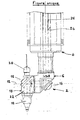
- This figure shows a laser wrist 2 surmounted by a spindle 4 of a vertical translation unit not shown for a five-axis laser cutting and welding machine.
- This wrist has a body 6 capable of rotating around the fourth axis 8, and an end portion 10 capable of rotating around the fifth axis 12.
- the body 6 is provided with a mirror 14.
- the end part 10 comprises a mirror 16, a laser nozzle 18 and a measuring probe 20.
- This measuring probe is fixed on the support 22 of this laser nozzle 18 and of this mirror 16, opposite to this nozzle and in the axis thereof.
- the spindle 4 is crossed by an axial bore 24 whose cross section is determined so as to allow a laser beam 26 of high power to pass with a device for bending the latter such as a mirror.
- This laser beam comes from a laser radiation generator outside the machine; it crosses spindle 4 after a journey inside, for example, structural profiles.
- An automatic operating cycle includes, for example, the following steps:
Landscapes
- Engineering & Computer Science (AREA)
- Physics & Mathematics (AREA)
- Optics & Photonics (AREA)
- Mechanical Engineering (AREA)
- Plasma & Fusion (AREA)
- Robotics (AREA)
- Laser Beam Processing (AREA)
- Manipulator (AREA)
- Length Measuring Devices By Optical Means (AREA)
Claims (1)
- Spindelgelenkeinheit für Laserstrahl-Schneid-und Schweißmaschinen, mit einer Spindel (4), die eine Axialbohrung (24) mit einer Achse (8) und mit einem geraden Querschnitt aufweist, der zum Durchlaß eines Laserstrahls (26) erhöhter Leistung ausreicht und mit einem Gelenk (2) am Ende der Spindel (4), mit zwei zusammenlaufenden Drehachsen (8, 12), wobei das Gelenk zwei Spiegel (14, 16) enthält zur zweifachen Ablenkung des Laserstrahls und wobei die beiden Spiegel (14,16) einerseits der Spindel (4) und andererseits einem Laserausgang (18) zugeordnet sind, der am Ende des Gelenks (2) um die Drehachse (12) verdrehbar ist und wobei ein Meßaufnehmer der Spindelgelenkeinheit zugeordnet ist, dadurch gekennzeichnet, daß der Aufnehmer (20) ein Meßfühler ist und daß der Fühler in der Achse des Laserausgangs (18) angeordnet ist gegenüber dem Laserausgang (18) bezüglich der Drehachse (12) des Ausgangs (18).
Applications Claiming Priority (2)
| Application Number | Priority Date | Filing Date | Title |
|---|---|---|---|
| FR8607537A FR2599287B1 (fr) | 1986-05-27 | 1986-05-27 | Ensemble poignet-broche pour machine de decoupe et de soudage par faisceau laser. |
| FR8607537 | 1986-05-27 |
Publications (2)
| Publication Number | Publication Date |
|---|---|
| EP0247930A1 EP0247930A1 (de) | 1987-12-02 |
| EP0247930B1 true EP0247930B1 (de) | 1990-11-28 |
Family
ID=9335666
Family Applications (1)
| Application Number | Title | Priority Date | Filing Date |
|---|---|---|---|
| EP87401152A Expired - Lifetime EP0247930B1 (de) | 1986-05-27 | 1987-05-22 | Spindelgelenkeinheit für Laserstrahlschweissmaschine |
Country Status (4)
| Country | Link |
|---|---|
| EP (1) | EP0247930B1 (de) |
| DE (1) | DE3766417D1 (de) |
| ES (1) | ES2019107B3 (de) |
| FR (1) | FR2599287B1 (de) |
Families Citing this family (5)
| Publication number | Priority date | Publication date | Assignee | Title |
|---|---|---|---|---|
| DE59002563D1 (de) * | 1990-01-20 | 1993-10-07 | Thyssen Industrie | Verfahren und Einrichtung zum Aneinanderschweissen von Stahlblechen mittels Laserstrahlschweissverfahren. |
| DE4025851A1 (de) * | 1990-08-16 | 1992-02-20 | Messerschmitt Boelkow Blohm | Einrichtung zur messung rueckgestreuter strahlung |
| DE4306282A1 (de) * | 1993-03-01 | 1994-09-15 | Emhart Inc | Verfahren und Vorrichtung zum Verschweißen eines Einschweißteils in einer eine Metallplatte und eine darüberliegende Metallauflage umfassenden Schweißstelle |
| CN111730210B (zh) * | 2020-06-09 | 2022-01-18 | 匠铜实业(杭州)有限公司 | 一种采用极坐标运动的双主轴激光雕刻机 |
| CN118848116B (zh) * | 2024-06-07 | 2026-01-20 | 中国长江电力股份有限公司 | Gil管道自动开孔设备及自动开孔方法 |
Family Cites Families (1)
| Publication number | Priority date | Publication date | Assignee | Title |
|---|---|---|---|---|
| IT1179924B (it) * | 1984-05-22 | 1987-09-16 | Prima Progetti Spa | Testa focalizzatrice per una macchina da taglio a raggi laser |
-
1986
- 1986-05-27 FR FR8607537A patent/FR2599287B1/fr not_active Expired
-
1987
- 1987-05-22 DE DE8787401152T patent/DE3766417D1/de not_active Expired - Fee Related
- 1987-05-22 EP EP87401152A patent/EP0247930B1/de not_active Expired - Lifetime
- 1987-05-22 ES ES87401152T patent/ES2019107B3/es not_active Expired - Lifetime
Also Published As
| Publication number | Publication date |
|---|---|
| DE3766417D1 (de) | 1991-01-10 |
| FR2599287A1 (fr) | 1987-12-04 |
| EP0247930A1 (de) | 1987-12-02 |
| FR2599287B1 (fr) | 1988-10-07 |
| ES2019107B3 (es) | 1991-06-01 |
Similar Documents
| Publication | Publication Date | Title |
|---|---|---|
| CA2028351A1 (fr) | Outillage de retouche d'aubes de rotor d'une turbomachine et procede de retouche utilisant cet outillage | |
| EP0247930B1 (de) | Spindelgelenkeinheit für Laserstrahlschweissmaschine | |
| EP1310314A1 (de) | Werkzeug, Maschine und Verfahren zum Bohren auf spiralförmiger Bahn | |
| JPH1199403A (ja) | 主軸装置 | |
| EP0700795A1 (de) | Markierungsgerät zum Aufbringen von Zweidimensionellen-Identifikationszeichen auf der Oberfläche eines Gegenstandes | |
| EP0436453A1 (de) | Werkzeugeinheit mit Fühler | |
| FR2534515A1 (fr) | Ensemble porte-outil vibrant | |
| FR2528373A1 (fr) | Dispositif de direction d'un vehicule a roues avant et arriere directrices | |
| EP1252967B1 (de) | Spindelstruktur | |
| FR2640538A1 (fr) | Machine-outil pour rectifier les gorges helicoidales d'un outil de coupe | |
| EP3307462B1 (de) | Drehmaschine und führungsbuchse | |
| EP0684170B1 (de) | Wischermodul für eine Kraftfahrzeugscheibe | |
| FR2707198A1 (fr) | Système de lubrification pour un porte-outil. | |
| EP0554629B1 (de) | Honmaschine mit ausdehnbarem Werkzeug | |
| FR2829952A1 (fr) | Machine d'usinage a mecanisme d'entrainement standardise | |
| CH630830A5 (fr) | Mecanisme de commande du porte-outils d'une machine transfert. | |
| EP1314501A1 (de) | Bohrkopf mit Werkzeugvorschub unabhàndlich des Drehens | |
| FR2496516A1 (fr) | Tete pour fraiseuse | |
| WO1992021455A1 (fr) | Tete de cambrage a outils multiples pour machine a cambrer les fils metalliques | |
| FR2644089A1 (fr) | Outil de fraisage | |
| FR2763296A1 (fr) | Systeme d'essuyage comportant un palier de guidage de l'arbre d'entrainement de l'essuie-glace | |
| FR2530801A1 (fr) | Capteur de position angulaire d'un arbre a angle de rotation limite | |
| FR2571289A1 (fr) | Dispositif d'orientation pour outil | |
| FR2682055A1 (fr) | Bac a dielectrique liquide pour machine a electro-erosion et machine a electro-erosion equipee d'un tel bac. | |
| BE1001080A6 (fr) | Outil d'usinage par enlevement de copeaux, en forme de doigt, pour equiper des machines d'usinage des surfaces. |
Legal Events
| Date | Code | Title | Description |
|---|---|---|---|
| PUAI | Public reference made under article 153(3) epc to a published international application that has entered the european phase |
Free format text: ORIGINAL CODE: 0009012 |
|
| 17P | Request for examination filed |
Effective date: 19870527 |
|
| AK | Designated contracting states |
Kind code of ref document: A1 Designated state(s): BE DE ES GB IT NL SE |
|
| 17Q | First examination report despatched |
Effective date: 19881129 |
|
| GRAA | (expected) grant |
Free format text: ORIGINAL CODE: 0009210 |
|
| AK | Designated contracting states |
Kind code of ref document: B1 Designated state(s): BE DE ES GB IT NL SE |
|
| ITF | It: translation for a ep patent filed | ||
| GBT | Gb: translation of ep patent filed (gb section 77(6)(a)/1977) | ||
| REF | Corresponds to: |
Ref document number: 3766417 Country of ref document: DE Date of ref document: 19910110 |
|
| PLBE | No opposition filed within time limit |
Free format text: ORIGINAL CODE: 0009261 |
|
| STAA | Information on the status of an ep patent application or granted ep patent |
Free format text: STATUS: NO OPPOSITION FILED WITHIN TIME LIMIT |
|
| 26N | No opposition filed | ||
| ITTA | It: last paid annual fee | ||
| EAL | Se: european patent in force in sweden |
Ref document number: 87401152.1 |
|
| PGFP | Annual fee paid to national office [announced via postgrant information from national office to epo] |
Ref country code: GB Payment date: 19970410 Year of fee payment: 11 |
|
| PGFP | Annual fee paid to national office [announced via postgrant information from national office to epo] |
Ref country code: BE Payment date: 19970417 Year of fee payment: 11 |
|
| PGFP | Annual fee paid to national office [announced via postgrant information from national office to epo] |
Ref country code: SE Payment date: 19970423 Year of fee payment: 11 |
|
| PGFP | Annual fee paid to national office [announced via postgrant information from national office to epo] |
Ref country code: NL Payment date: 19970428 Year of fee payment: 11 |
|
| PGFP | Annual fee paid to national office [announced via postgrant information from national office to epo] |
Ref country code: DE Payment date: 19970510 Year of fee payment: 11 |
|
| PGFP | Annual fee paid to national office [announced via postgrant information from national office to epo] |
Ref country code: ES Payment date: 19970519 Year of fee payment: 11 |
|
| PG25 | Lapsed in a contracting state [announced via postgrant information from national office to epo] |
Ref country code: GB Free format text: LAPSE BECAUSE OF NON-PAYMENT OF DUE FEES Effective date: 19980522 |
|
| PG25 | Lapsed in a contracting state [announced via postgrant information from national office to epo] |
Ref country code: SE Free format text: LAPSE BECAUSE OF NON-PAYMENT OF DUE FEES Effective date: 19980523 Ref country code: ES Free format text: LAPSE BECAUSE OF EXPIRATION OF PROTECTION Effective date: 19980523 |
|
| PG25 | Lapsed in a contracting state [announced via postgrant information from national office to epo] |
Ref country code: BE Free format text: LAPSE BECAUSE OF NON-PAYMENT OF DUE FEES Effective date: 19980531 |
|
| BERE | Be: lapsed |
Owner name: RENAULT AUTOMATION Effective date: 19980531 |
|
| PG25 | Lapsed in a contracting state [announced via postgrant information from national office to epo] |
Ref country code: NL Free format text: LAPSE BECAUSE OF NON-PAYMENT OF DUE FEES Effective date: 19981201 |
|
| GBPC | Gb: european patent ceased through non-payment of renewal fee |
Effective date: 19980522 |
|
| EUG | Se: european patent has lapsed |
Ref document number: 87401152.1 |
|
| NLV4 | Nl: lapsed or anulled due to non-payment of the annual fee |
Effective date: 19981201 |
|
| PG25 | Lapsed in a contracting state [announced via postgrant information from national office to epo] |
Ref country code: DE Free format text: LAPSE BECAUSE OF NON-PAYMENT OF DUE FEES Effective date: 19990302 |
|
| REG | Reference to a national code |
Ref country code: ES Ref legal event code: FD2A Effective date: 20000201 |
|
| PG25 | Lapsed in a contracting state [announced via postgrant information from national office to epo] |
Ref country code: IT Free format text: LAPSE BECAUSE OF NON-PAYMENT OF DUE FEES;WARNING: LAPSES OF ITALIAN PATENTS WITH EFFECTIVE DATE BEFORE 2007 MAY HAVE OCCURRED AT ANY TIME BEFORE 2007. THE CORRECT EFFECTIVE DATE MAY BE DIFFERENT FROM THE ONE RECORDED. Effective date: 20050522 |