EP0247416B1 - Gleichlauf- und Bremssteuerung - Google Patents
Gleichlauf- und Bremssteuerung Download PDFInfo
- Publication number
- EP0247416B1 EP0247416B1 EP87106748A EP87106748A EP0247416B1 EP 0247416 B1 EP0247416 B1 EP 0247416B1 EP 87106748 A EP87106748 A EP 87106748A EP 87106748 A EP87106748 A EP 87106748A EP 0247416 B1 EP0247416 B1 EP 0247416B1
- Authority
- EP
- European Patent Office
- Prior art keywords
- motors
- motor
- synchronizing
- braking control
- current
- Prior art date
- Legal status (The legal status is an assumption and is not a legal conclusion. Google has not performed a legal analysis and makes no representation as to the accuracy of the status listed.)
- Expired - Lifetime
Links
- 238000004804 winding Methods 0.000 claims abstract description 12
- 238000000034 method Methods 0.000 description 9
- 230000000694 effects Effects 0.000 description 2
- 241000549194 Euonymus europaeus Species 0.000 description 1
- 230000006378 damage Effects 0.000 description 1
- 238000011161 development Methods 0.000 description 1
- 230000018109 developmental process Effects 0.000 description 1
- 210000004072 lung Anatomy 0.000 description 1
- 230000007257 malfunction Effects 0.000 description 1
- 230000010363 phase shift Effects 0.000 description 1
- 230000001960 triggered effect Effects 0.000 description 1
Images

Classifications
-
- H—ELECTRICITY
- H02—GENERATION; CONVERSION OR DISTRIBUTION OF ELECTRIC POWER
- H02P—CONTROL OR REGULATION OF ELECTRIC MOTORS, ELECTRIC GENERATORS OR DYNAMO-ELECTRIC CONVERTERS; CONTROLLING TRANSFORMERS, REACTORS OR CHOKE COILS
- H02P3/00—Arrangements for stopping or slowing electric motors, generators, or dynamo-electric converters
-
- H—ELECTRICITY
- H02—GENERATION; CONVERSION OR DISTRIBUTION OF ELECTRIC POWER
- H02P—CONTROL OR REGULATION OF ELECTRIC MOTORS, ELECTRIC GENERATORS OR DYNAMO-ELECTRIC CONVERTERS; CONTROLLING TRANSFORMERS, REACTORS OR CHOKE COILS
- H02P6/00—Arrangements for controlling synchronous motors or other dynamo-electric motors using electronic commutation dependent on the rotor position; Electronic commutators therefor
- H02P6/24—Arrangements for stopping
-
- G—PHYSICS
- G11—INFORMATION STORAGE
- G11B—INFORMATION STORAGE BASED ON RELATIVE MOVEMENT BETWEEN RECORD CARRIER AND TRANSDUCER
- G11B15/00—Driving, starting or stopping record carriers of filamentary or web form; Driving both such record carriers and heads; Guiding such record carriers or containers therefor; Control thereof; Control of operating function
- G11B15/18—Driving; Starting; Stopping; Arrangements for control or regulation thereof
- G11B15/46—Controlling, regulating, or indicating speed
- G11B15/467—Controlling, regulating, or indicating speed in arrangements for recording or reproducing wherein both record carriers and heads are driven
- G11B15/473—Controlling, regulating, or indicating speed in arrangements for recording or reproducing wherein both record carriers and heads are driven by controlling the speed of the heads
-
- H—ELECTRICITY
- H02—GENERATION; CONVERSION OR DISTRIBUTION OF ELECTRIC POWER
- H02P—CONTROL OR REGULATION OF ELECTRIC MOTORS, ELECTRIC GENERATORS OR DYNAMO-ELECTRIC CONVERTERS; CONTROLLING TRANSFORMERS, REACTORS OR CHOKE COILS
- H02P6/00—Arrangements for controlling synchronous motors or other dynamo-electric motors using electronic commutation dependent on the rotor position; Electronic commutators therefor
- H02P6/04—Arrangements for controlling or regulating the speed or torque of more than one motor
Definitions
- the individual mutually corresponding windings of the two identical motors for the stopping process after switching off are connected in parallel to one another.
- the individual windings are polarized during the stopping process so that the voltages generated have the same direction at the same speed.
- the individual partial voltages are in phase and an unintentional relative change of the speeds to one another cannot take place.
- phase differences i.e. tensions are generated which are in phase opposition to one another in sections.
- This back emf causes an almost abrupt braking effect on both motors, so that the possibility of unintentional relative speed deviations of the motors from one another after the switch-off process is avoided.
- the head drum 8 forms a unit with motor 6, which is displaceably mounted on a linkage 7a, 7b via slide bearings 20a, 20b, 20c .
- the electronically commutatable coils 16 are arranged, which are connected in parallel with the corresponding electronically commutated coils 15, of the motor 1 generating the stroke, during the switch-off process.
- the head drum 8 is firmly connected to the shaft 12 and the rotor of motor 6, to which the magnets 17 are attached.
- the shaft 12 is supported in the slide bearings 11a, 11b. It carries a threaded spindle 5 at its free end. This protrudes into a threaded bushing 4 which is firmly connected to the shaft 2 and rotor 14 of motor 1.
- Motor 1 is fixed to the chassis 3, which also carries the linkage 7.
- a magnetic tape 9 is placed on the head drum 8 and is in contact with a magnetic head 21.
- the signals to be recorded or emitted are forwarded by the magnetic head 21 to the windings of a rotary transmitter 10, the fixed part of which is connected to the fixed part of Motgor 6 via the connecting part 13.
- both motors 1 and 6 have the same rotational speeds in the same direction of rotation, the mechanical distance between the motors is constant. If, however, motor 1 makes slight, for example sinusoidal, changes in speed compared to the speed of motor 6, motor 6 and thus the head drum are displaced in the direction of the arrow via bushing 4 and spindle 5. Thus, magnetic tracks 9 which are adjacent to one another and run parallel to one another and are written on magnetic tape 9, which is guided in a fixed manner to chassis 3, in accordance with EP-A-0224211. From the figure it can be seen that after a shutdown without electronic control, different rotating masses act on the shafts of the motors 1 and 6, so that a lifting movement is caused by the spindle 4, 5 without special measures, which can lead to the disturbance of the arrangement . In order to avoid this, if the stroke is exceeded by the limit switches 18 and 19, for example, a shutdown process for both motors can be triggered, in which the individual windings simultaneously lungs of motors 1 and 6 are connected in parallel.
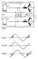
- FIG. 2 shows a circuit of the synchronization and braking control according to the invention.
- the windings 24, 25 and 26 of a first, three-strand motor which can be controlled in speed by the control device 22 in star connection are shown, which are mechanically connected to the windings 27, 28, and 29 via a spindle shown in FIG. 1 with a second motor is coupled.
- the structure and circuit of the second motor corresponds to that of the first motor. Its speed is also controlled electronically by control unit 23. Both control units are connected to one another via a line 34, whereby a desired adjustment of the two speeds to one another can take place during operation.
- Fig. 3a shows e.g. the voltage curve in coil 24 at the switch-off torque and FIG. 3b the curve in the parallel-connected coil 27 at the switch-off torque. Both voltages are in phase at the same speed, so that no relative movement can take place between the two motors. If, on the other hand, the speed of an engine is e.g. changed by different flywheel masses during the coasting process compared to the speed of the other motor, e.g. a phase shift, as shown in Fig. 3c compared to 3a and 3b. In this state, the voltages in the shaded area are directed towards each other, which results in electrical braking by the back emf. The further the phases differ from one another, the stronger the braking effect, i.e. braking is almost abrupt, so that undesired relative movements between the two motors are avoided.
- the motor windings are shown in star connection as an example. But even in the case of a delta connection of the windings, it is possible, in the absence of a supply voltage, to perform a parallel connection of corresponding windings with the aid of the relay contact.
Landscapes
- Engineering & Computer Science (AREA)
- Power Engineering (AREA)
- Stopping Of Electric Motors (AREA)
- Control Of Multiple Motors (AREA)
- Control Of Motors That Do Not Use Commutators (AREA)
- Braking Systems And Boosters (AREA)
- Electric Propulsion And Braking For Vehicles (AREA)
- Braking Arrangements (AREA)
- Regulating Braking Force (AREA)
- Control Of Ac Motors In General (AREA)
Priority Applications (1)
| Application Number | Priority Date | Filing Date | Title |
|---|---|---|---|
| AT87106748T ATE55662T1 (de) | 1986-05-17 | 1987-05-08 | Gleichlauf- und bremssteuerung. |
Applications Claiming Priority (2)
| Application Number | Priority Date | Filing Date | Title |
|---|---|---|---|
| DE19863616845 DE3616845A1 (de) | 1986-05-17 | 1986-05-17 | Gleichlauf- und bremssteuerung |
| DE3616845 | 1986-05-17 |
Publications (2)
| Publication Number | Publication Date |
|---|---|
| EP0247416A1 EP0247416A1 (de) | 1987-12-02 |
| EP0247416B1 true EP0247416B1 (de) | 1990-08-16 |
Family
ID=6301173
Family Applications (1)
| Application Number | Title | Priority Date | Filing Date |
|---|---|---|---|
| EP87106748A Expired - Lifetime EP0247416B1 (de) | 1986-05-17 | 1987-05-08 | Gleichlauf- und Bremssteuerung |
Country Status (7)
| Country | Link |
|---|---|
| EP (1) | EP0247416B1 (es) |
| JP (1) | JPS62277097A (es) |
| KR (1) | KR910001784B1 (es) |
| AT (1) | ATE55662T1 (es) |
| DE (2) | DE3616845A1 (es) |
| ES (1) | ES2016946B3 (es) |
| GR (1) | GR3001076T3 (es) |
Family Cites Families (5)
| Publication number | Priority date | Publication date | Assignee | Title |
|---|---|---|---|---|
| DE2106898A1 (de) * | 1971-02-13 | 1972-08-24 | Siemens Ag | Spinnturbine mit einem drehzahlgeregelten, abbremsbaren elektrischen Antriebsmotor |
| US4347536A (en) * | 1979-01-10 | 1982-08-31 | Hitachi, Ltd. | Rotary cylinder apparatus |
| JPS592594A (ja) * | 1982-06-25 | 1984-01-09 | Hitachi Ltd | モ−タ群の電源回路 |
| DE3307324A1 (de) * | 1983-03-02 | 1984-09-06 | Telefunken Fernseh Und Rundfunk Gmbh, 3000 Hannover | Videorecorder mit schraegspuraufzeichnung |
| DE3542064A1 (de) * | 1985-11-28 | 1987-06-04 | Thomson Brandt Gmbh | Kopfradanordnung fuer einen recorder |
-
1986
- 1986-05-17 DE DE19863616845 patent/DE3616845A1/de not_active Withdrawn
-
1987
- 1987-05-08 AT AT87106748T patent/ATE55662T1/de not_active IP Right Cessation
- 1987-05-08 DE DE8787106748T patent/DE3764312D1/de not_active Expired - Fee Related
- 1987-05-08 ES ES87106748T patent/ES2016946B3/es not_active Expired - Lifetime
- 1987-05-08 EP EP87106748A patent/EP0247416B1/de not_active Expired - Lifetime
- 1987-05-16 KR KR1019870004839A patent/KR910001784B1/ko not_active Expired
- 1987-05-18 JP JP62119141A patent/JPS62277097A/ja active Granted
-
1990
- 1990-11-15 GR GR90400919T patent/GR3001076T3/el unknown
Also Published As
| Publication number | Publication date |
|---|---|
| ES2016946B3 (es) | 1990-12-16 |
| JPH0568200B2 (es) | 1993-09-28 |
| KR910001784B1 (ko) | 1991-03-23 |
| DE3764312D1 (de) | 1990-09-20 |
| KR870011744A (ko) | 1987-12-26 |
| JPS62277097A (ja) | 1987-12-01 |
| EP0247416A1 (de) | 1987-12-02 |
| ATE55662T1 (de) | 1990-09-15 |
| GR3001076T3 (en) | 1992-04-17 |
| DE3616845A1 (de) | 1987-11-19 |
Similar Documents
| Publication | Publication Date | Title |
|---|---|---|
| EP1017160B1 (de) | Verfahren zur Kommutierung eines elektronisch kommutierten bürstenlosen Mehrphasen-Permanent-Magnetmotors | |
| DE3120559C2 (es) | ||
| DE2556952A1 (de) | Kombiniertes, digitales steuerungs- und regelungssystem fuer einen gleichstrommotor | |
| DE3740551C2 (de) | Datenspeichergerät mit einem rotierenden Datenträger | |
| EP1699676B1 (de) | Verfahren zum abbremsen eines elektromotors und elektrischer antrieb | |
| EP0774829B1 (de) | Schaltung mit einem digitalen Controller für den Betrieb eines Synchronmotors | |
| EP0247416B1 (de) | Gleichlauf- und Bremssteuerung | |
| DE3128627A1 (de) | Servoeinrichtung zur reglung der geschwindigkeit und phase einer rotierenden vorrichtung | |
| EP0224211B1 (de) | Kopfradanordnung für einen Recorder | |
| EP0196539B1 (de) | Digitale Drehzahlregelschaltung für einen Gleichstrommotor | |
| DE102004019284A1 (de) | Vorrichtung zum Betrieb eines Synchronmotors | |
| EP0334160A2 (de) | Einrichtung zur Einstellung des Lastwinkels eines elektrischen Schrittmotors | |
| DE10207549B4 (de) | Verfahren und Vorrichtung zum Betrieb eines Synchronmotors | |
| EP1070383B1 (de) | Verfahren und vorrichtung zur ansteuerung eines elektronisch kommutierten mehrphasen-gleichstrommotors | |
| DE2044736C2 (de) | Anordnung zur Regelung der Geschwindigkeit zwischen zwei relativ zueinander bewegbaren Teilen | |
| DE3409300C1 (de) | Kreuzschlittenmaschine mit numerischer Bahnsteuerung für die Bearbeitung von Glasscheiben | |
| EP0324396A2 (de) | Verfahren zur Kommutierung von Spulensträngen eines Gleichstrommotors | |
| DE19735581A1 (de) | Spultrommelantrieb einer Kreuzspulen herstellenden Textilmaschine | |
| DE4125892C2 (de) | Steuerungsanordnung für einen winkelschrittgesteuerten Elektromotor | |
| EP0372095B1 (de) | Elektromotorischer Antrieb | |
| DE69123419T2 (de) | Aufzeichnungsgerät und Wiedergabegerät mit drehbaren Magnetköpfen | |
| DE19853452C1 (de) | Robotervorrichtung | |
| EP0257562A2 (de) | Hubeinrichtung für einen Rotor, insbesondere für die Kopfradanordnung eines Recorders | |
| DD282552A5 (de) | Schaltungsanordnung zum bremsen von drehstrommotoren | |
| DE3305217C1 (de) | Vorrichtung zur Winkel- und Wegmessung an einem Servosystem |
Legal Events
| Date | Code | Title | Description |
|---|---|---|---|
| PUAI | Public reference made under article 153(3) epc to a published international application that has entered the european phase |
Free format text: ORIGINAL CODE: 0009012 |
|
| AK | Designated contracting states |
Kind code of ref document: A1 Designated state(s): AT BE CH DE ES FR GB GR IT LI LU NL SE |
|
| 17P | Request for examination filed |
Effective date: 19880105 |
|
| 17Q | First examination report despatched |
Effective date: 19900125 |
|
| GRAA | (expected) grant |
Free format text: ORIGINAL CODE: 0009210 |
|
| ITF | It: translation for a ep patent filed | ||
| AK | Designated contracting states |
Kind code of ref document: B1 Designated state(s): AT BE CH DE ES FR GB GR IT LI LU NL SE |
|
| REF | Corresponds to: |
Ref document number: 55662 Country of ref document: AT Date of ref document: 19900915 Kind code of ref document: T |
|
| REF | Corresponds to: |
Ref document number: 3764312 Country of ref document: DE Date of ref document: 19900920 |
|
| GBT | Gb: translation of ep patent filed (gb section 77(6)(a)/1977) | ||
| ET | Fr: translation filed | ||
| ITTA | It: last paid annual fee | ||
| PLBE | No opposition filed within time limit |
Free format text: ORIGINAL CODE: 0009261 |
|
| STAA | Information on the status of an ep patent application or granted ep patent |
Free format text: STATUS: NO OPPOSITION FILED WITHIN TIME LIMIT |
|
| REG | Reference to a national code |
Ref country code: GR Ref legal event code: FG4A Free format text: 3001076 |
|
| 26N | No opposition filed | ||
| PGFP | Annual fee paid to national office [announced via postgrant information from national office to epo] |
Ref country code: LU Payment date: 19920423 Year of fee payment: 6 |
|
| PGFP | Annual fee paid to national office [announced via postgrant information from national office to epo] |
Ref country code: GB Payment date: 19920429 Year of fee payment: 6 |
|
| PGFP | Annual fee paid to national office [announced via postgrant information from national office to epo] |
Ref country code: ES Payment date: 19920511 Year of fee payment: 6 |
|
| PGFP | Annual fee paid to national office [announced via postgrant information from national office to epo] |
Ref country code: AT Payment date: 19920512 Year of fee payment: 6 |
|
| PGFP | Annual fee paid to national office [announced via postgrant information from national office to epo] |
Ref country code: SE Payment date: 19920515 Year of fee payment: 6 |
|
| PGFP | Annual fee paid to national office [announced via postgrant information from national office to epo] |
Ref country code: BE Payment date: 19920520 Year of fee payment: 6 |
|
| PGFP | Annual fee paid to national office [announced via postgrant information from national office to epo] |
Ref country code: GR Payment date: 19920521 Year of fee payment: 6 |
|
| PGFP | Annual fee paid to national office [announced via postgrant information from national office to epo] |
Ref country code: FR Payment date: 19920526 Year of fee payment: 6 |
|
| PGFP | Annual fee paid to national office [announced via postgrant information from national office to epo] |
Ref country code: CH Payment date: 19920529 Year of fee payment: 6 |
|
| PGFP | Annual fee paid to national office [announced via postgrant information from national office to epo] |
Ref country code: NL Payment date: 19920531 Year of fee payment: 6 |
|
| PGFP | Annual fee paid to national office [announced via postgrant information from national office to epo] |
Ref country code: DE Payment date: 19920731 Year of fee payment: 6 |
|
| EPTA | Lu: last paid annual fee | ||
| PG25 | Lapsed in a contracting state [announced via postgrant information from national office to epo] |
Ref country code: LU Free format text: LAPSE BECAUSE OF NON-PAYMENT OF DUE FEES Effective date: 19930508 Ref country code: GB Effective date: 19930508 Ref country code: AT Effective date: 19930508 |
|
| PG25 | Lapsed in a contracting state [announced via postgrant information from national office to epo] |
Ref country code: SE Effective date: 19930509 |
|
| PG25 | Lapsed in a contracting state [announced via postgrant information from national office to epo] |
Ref country code: ES Free format text: LAPSE BECAUSE OF NON-PAYMENT OF DUE FEES Effective date: 19930510 |
|
| PG25 | Lapsed in a contracting state [announced via postgrant information from national office to epo] |
Ref country code: LI Effective date: 19930531 Ref country code: CH Effective date: 19930531 Ref country code: BE Effective date: 19930531 |
|
| BERE | Be: lapsed |
Owner name: DEUTSCHE THOMSON-BRANDT G.M.B.H. Effective date: 19930531 |
|
| PG25 | Lapsed in a contracting state [announced via postgrant information from national office to epo] |
Ref country code: GR Free format text: THE PATENT HAS BEEN ANNULLED BY A DECISION OF A NATIONAL AUTHORITY Effective date: 19931130 |
|
| PG25 | Lapsed in a contracting state [announced via postgrant information from national office to epo] |
Ref country code: NL Effective date: 19931201 |
|
| GBPC | Gb: european patent ceased through non-payment of renewal fee |
Effective date: 19930508 |
|
| NLV4 | Nl: lapsed or anulled due to non-payment of the annual fee | ||
| PG25 | Lapsed in a contracting state [announced via postgrant information from national office to epo] |
Ref country code: FR Effective date: 19940131 |
|
| REG | Reference to a national code |
Ref country code: CH Ref legal event code: PL |
|
| PG25 | Lapsed in a contracting state [announced via postgrant information from national office to epo] |
Ref country code: DE Effective date: 19940201 |
|
| REG | Reference to a national code |
Ref country code: FR Ref legal event code: ST |
|
| REG | Reference to a national code |
Ref country code: GR Ref legal event code: MM2A Free format text: 3001076 |
|
| EUG | Se: european patent has lapsed |
Ref document number: 87106748.4 Effective date: 19931210 |
|
| REG | Reference to a national code |
Ref country code: ES Ref legal event code: FD2A Effective date: 19990201 |
|
| PG25 | Lapsed in a contracting state [announced via postgrant information from national office to epo] |
Ref country code: IT Free format text: LAPSE BECAUSE OF NON-PAYMENT OF DUE FEES;WARNING: LAPSES OF ITALIAN PATENTS WITH EFFECTIVE DATE BEFORE 2007 MAY HAVE OCCURRED AT ANY TIME BEFORE 2007. THE CORRECT EFFECTIVE DATE MAY BE DIFFERENT FROM THE ONE RECORDED. Effective date: 20050508 |