EP0247085B1 - Dokumentenleitanordnung - Google Patents
Dokumentenleitanordnung Download PDFInfo
- Publication number
- EP0247085B1 EP0247085B1 EP86906547A EP86906547A EP0247085B1 EP 0247085 B1 EP0247085 B1 EP 0247085B1 EP 86906547 A EP86906547 A EP 86906547A EP 86906547 A EP86906547 A EP 86906547A EP 0247085 B1 EP0247085 B1 EP 0247085B1
- Authority
- EP
- European Patent Office
- Prior art keywords
- document
- cupping
- documents
- receiving means
- flexible band
- Prior art date
- Legal status (The legal status is an assumption and is not a legal conclusion. Google has not performed a legal analysis and makes no representation as to the accuracy of the status listed.)
- Expired
Links
- 230000007246 mechanism Effects 0.000 title claims abstract description 16
- 239000000463 material Substances 0.000 claims description 4
- 239000002985 plastic film Substances 0.000 claims description 2
- 229920006255 plastic film Polymers 0.000 claims description 2
- 238000000034 method Methods 0.000 description 3
- 238000011144 upstream manufacturing Methods 0.000 description 3
- 230000000717 retained effect Effects 0.000 description 2
- 229920002799 BoPET Polymers 0.000 description 1
- 239000005041 Mylar™ Substances 0.000 description 1
- 235000014443 Pyrus communis Nutrition 0.000 description 1
- 238000013459 approach Methods 0.000 description 1
- 238000010586 diagram Methods 0.000 description 1
- 230000037303 wrinkles Effects 0.000 description 1
Images

Classifications
-
- B—PERFORMING OPERATIONS; TRANSPORTING
- B65—CONVEYING; PACKING; STORING; HANDLING THIN OR FILAMENTARY MATERIAL
- B65H—HANDLING THIN OR FILAMENTARY MATERIAL, e.g. SHEETS, WEBS, CABLES
- B65H31/00—Pile receivers
- B65H31/04—Pile receivers with movable end support arranged to recede as pile accumulates
- B65H31/06—Pile receivers with movable end support arranged to recede as pile accumulates the articles being piled on edge
-
- B—PERFORMING OPERATIONS; TRANSPORTING
- B65—CONVEYING; PACKING; STORING; HANDLING THIN OR FILAMENTARY MATERIAL
- B65H—HANDLING THIN OR FILAMENTARY MATERIAL, e.g. SHEETS, WEBS, CABLES
- B65H29/00—Delivering or advancing articles from machines; Advancing articles to or into piles
- B65H29/70—Article bending or stiffening arrangements
-
- B—PERFORMING OPERATIONS; TRANSPORTING
- B65—CONVEYING; PACKING; STORING; HANDLING THIN OR FILAMENTARY MATERIAL
- B65H—HANDLING THIN OR FILAMENTARY MATERIAL, e.g. SHEETS, WEBS, CABLES
- B65H31/00—Pile receivers
- B65H31/26—Auxiliary devices for retaining articles in the pile
-
- B—PERFORMING OPERATIONS; TRANSPORTING
- B65—CONVEYING; PACKING; STORING; HANDLING THIN OR FILAMENTARY MATERIAL
- B65H—HANDLING THIN OR FILAMENTARY MATERIAL, e.g. SHEETS, WEBS, CABLES
- B65H2701/00—Handled material; Storage means
- B65H2701/10—Handled articles or webs
- B65H2701/19—Specific article or web
- B65H2701/1912—Banknotes, bills and cheques or the like
Definitions
- This invention relates to a document guide mechanism which is used to guide documents into pockets as is done in document processing machines such as proof and sorting machines, for example (see for instance DE-B-1283575).
- Some of the problems with feeding financial documents, like checks, for example, are due to the extreme variation in size and condition of the documents and to the materials from which these documents are made.
- the sizes of the documents processed in a financial proof machine can range from about 6.35 centimetres to 11.43 centimetres in height and from about 11.43 centimetres to 22.86 centimetres in length in an intermixed batch of documents.
- Many of the documents like checks, for example, have been carried in wallets and have a "U"-bend in them. Others are cut, or have bent corners or wrinkles in them.
- Some checks are very thin and flexible while other checks are stiff and made from card stock. It is apparent that when 250 to 300 of such documents are grouped together to be processed in a batch as is done in processing financial documents, the variation in size, condition and materials mentioned presents problems.
- One of the operations which is performed in the processing of financial documents is to process a batch of such documents on a machine which performs a sorting function.
- This machine has a plurality of pockets into which the documents are routed and stacked based on certain data read from the documents. For example, all documents of a certain type or destination end up in a designated pocket while being retained in the processing sequence. As the documents accumulate in a pocket, the documents have a tendency to "fan out" and rest against a rib (feeding line) along which the incoming documents are guided. When this happens, the leading edge of an incoming document can hit the trailing edges of the pocketed documents causing problems.
- An object of the present invention is to alleviate the problems mentioned earlier herein.
- a document guide mechanism including receiving means for receiving documents to be pocketed, and feeding means for feeding said documents sequentially along a feed path to said receiving means, characterized by cupping means positioned between said feeding means and said receiving means for stiffening a document passing therethrough by forming concave and convex sides on said document, said cupping means including a cupping rib which is positioned along one side of said path where said concave side is formed by said cupping means, and a flexible band having a portion which is arranged to extend from said one side of said feed path across said feed path so as to be engaged by the leading edge of a document being fed by said feeding means, said flexible band being associated with back-up means positioned substantially parallel to said feed path and being spaced from said feed path on said one side thereof, and said flexible band having operating parameters to enable said flexible band to form a wave Which progresses from said cupping means towards said receiving means as the leading edge of a document being fed progresses from said cupping means towards said receiving means to thereby move trail
- Some advantages of a document guide mechanism in accordance with the present invention are that it is low in cost, and simple to install.
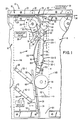
- Fig. 1 is a general, plan view of a portion of a document processing machine in the form of a sorter 10 which has a plurality of identical document guide mechanisms or sorting pockets 12, 14, and 16, for example, with only pocket 14 being shown in detail. Naturally, this invention may be used with a single pocket machine.
- the dashed lines 14a and 14b show the general side boundaries of the pocket 14.
- Fig. 1 The upper end of Fig. 1 includes a portion of a document track 18 in which documents, like 20, are fed to the various pockets 12, 14 and 16 for sorting and stacking.
- the document track 18 is conventional, and it is comprised of upstanding walls 22 and 24 which are spaced apart to receive a document 20 therebetween.
- the wall 24 is suitably slotted to receive the periphery of a document driving roller 26, and similarly, wall 22 is slotted to receive the periphery of an associated pinch roller 28.
- the driving roller 26 is rotated by a conventional transport drive 30 which is controlled by a controller 32 (Fig. 2) which also controls the operation of the sorter 10.
- the controller 32 actuates an appropriate selector, like 36 and 38 (Fig. 2), to divert the approaching document 20 into the appropriate pocket, like 14 or 16, for example, in accordance with processing instructions retained by the controller 32.
- Each selector, like 36 is comprised of an actuator which is coupled to a diverter 40 which is mounted on a shaft 42.
- a tension spring 44 is used to rotate the diverter 40 in a counterclockwise direction from the position shown in Fig. 1 to a position in which the end 45 is moved out of the track 18 to permit documents to pass thereby.
- the diverter 40 is moved to the position shown in Fig. 1 to thereby divert the document 20 into the pocket 14.
- the pockets 12, 14 and 16 are identical; consequently, only a discussion of pocket 14 will follow.
- Pocket 14 (Fig. 1) has an upstream end located between the periphery of driving roller 26 and an associated pinch roller 46, and it also has a downstream end which is located between the periphery of a drive roller 48 and a pusher plate 50.
- the documents 20 are fed between the upstream and downstream ends mentioned along a feeding line positioned therebetween and represented by dashed line 52.
- a receiving means designated generally as 54 (Fig. 1) is positioned at the downstream end of the pocket 14, and its function is to receive and stack the documents which are being pocketed.
- the receiving means 54 includes the pusher plate 50 and drive roller 48 already alluded to, and it also includes a stationary wall 56, a stop wall 58, and a full sensor 60 for detecting when the receiving means 54 is full.
- a similar full sensor 61 (Fig. 2) is associated with pocket 16.
- the very first document 20 received in the pocket 14 is fed between the stationary wall 56 and the pusher plate 50.
- each subsequent document is placed in front of the prior document. Some may view the operation as having each subsequent document placed behind (to the right as viewed in Fig. 1) of the prior document.
- the most recent document 20 inserted properly into the receiving means 54 will be located next to the stationary wall 56.
- the pusher plate 50 is moved to the left (as viewed in Fig. 1) to accommodate the resulting increasing stack.
- the pusher plate 50 is resiliently biased to move towards the stationary wall 56 by a tension spring 62 which is shown only schematically.
- a mounting plate 64 is positioned generally horizontally within the sorter 10. The pusher plate 50 is mounted for parallel movement relative to the stationary plate 56 via a "four-bar, parallel-motion mechanism" which includes the links 50-1 and 50-2.
- link 50-1 is pivotally joined to the pusher plate 50 by a pin 66, and the remaining end of link 50-1 is pivotally joined to a pin 68 which is upstanding from the mounting plate 64.
- link 50-2 is pivotally joined to the pusher plate 50 by a pin 70, and the remaining end is pivotally joined to a pin 72 which is upstanding from the mounting plate 64.
- the full sensor 60 sends a signal to the controller 32 (Fig. 2) to stop the transport drive 30.
- the controller 32 Fig. 2
- operation of the document sorting function is resumed by actuating a resume switch 76 associated with the controller 32.
- the sorter 10 also includes a cupping means 78 which is located between the driving roller 26 and the receiving means 54.
- the purpose of the cupping means 78 is to provide some rigidity or stiffness to the documents 20 as they are moved along the feeding line 52 towards the receiving means 54. In the embodiment described, the documents 20 are moved at a velocity of 254 centimetres per second towards the receiving means 54.
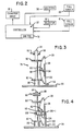
- the cupping means 78 includes cupping rollers 80 and 82 (Fig. 3) and a cupping rib designated generally as -83.
- the rollers 80 and 82 have elastomeric peripheries to engage a document 20 to drive it towards the receiving means 54.
- Rollers 80 and 82 are fixed to a shaft 84 to rotate therewith, and shaft 84 is mounted perpendicularly to mounting plate 64 for rotation in a clockwise direction as viewed in Fig. 1.
- the means for mounting the shaft 84 is conventional and is shown conveniently as a bushing 86 which is fixed to the mounting plate 64.
- the upper end of shaft 84 (Fig. 3) has a pulley 88 fixed thereto to rotate the shaft 84 and the rollers 80 and 82 thereon.
- the pulley 88 is driven by an "0- ring" belt 90 which is coupled to a driving pulley 92 associated with the driving roller 26.
- the distance between the cupping rollers 80 and 82 is about 6.35 centimetres to handle the range of document sizes mentioned earlier herein; however, the distance can be changed to accommodate different sizes as part of an initial set up.
- the cupping rib 83 alluded to earlier herein has a generally-planar, horizontal section 94 which is positioned between the cupping rollers 80 and 82 as shown in Fig. 3.
- the cupping rib 83 has an edge 96 which extends along the feeding line 52 as shown in Fig. 1, and it also has a rib 98 to provide rigidity to the cupping rib 83.
- the cupping rib 83 is conventionally mounted on the mounting plate 64 by a mounting bracket 100 and fasteners 102.
- the cupping rib 83 is closer to the longitudinal axis of the shaft 84 than are the peripheries of the cupping rollers 80 and 82; this changes the form of a document 20 from a generally flat planar one to one which is formed into a portion of a cylindrical wall with the concave side facing the cupping rib 83 and the convex side facing the cupping rollers 80 and 82. Forming a document into a portion of a cylindrical wall increases the stiffness or rigidity of the document 20 and thereby facilitates the transfer of documents to the receiving means 54.
- the cupping rib 83 also includes a back-up rib 104 which depends from the underside of the cupping rib 83 as viewed best in Fig. 4.
- the back-up rib 104 is positioned parallel to the leading edge 96 of the cupping rib 83 and is positioned a small distance away from the leading edge 96 thereof. The function of the back-up rib 104 will be described hereinafter.
- the pocket 14 also includes a flexible band designated generally as 106 (Fig. 1) whose function is to facilitate the transfer of documents 20 into the receiving means 54.
- the band 106 assumes the shape shown in Fig. 1.
- the band 106 is exaggerated in thickness to facilitate a showing thereof; however, in the embodiment described, the band 106 is made of plastic film material like MYLAR (a trademark of E.I. Dupont de Nemours & Company), having a thickness of approximately 0.01 centimetre, a width of approximately 0.70 centimetre, and a free-loop length of approximately 16 centimetres as operating parameters for handling the range of sizes of documents mentioned earlier herein.
- MYLAR a trademark of E.I. Dupont de Nemours & Company
- the free-loop length of about 16 centimetres is approximately of the maximum length of documents 20 processed in the embodiment described.
- the band 106 has one end 106-1 which is secured to the rib 98 (Fig. 4), with the free-loop length of the band 106 beginning at the point designated by arrow 108 (Fig. 1) and extending to the point designated by arrow 110 where the remaining end 106-2 is secured to the rib 98.
- the rib 98 is angled near the area 98-1 of rib 98; this forms the band 106 into a somewhat bulbous or pear shape at the downstream end of the band 106.
- Fig. 1 shows the position of the band 106 when no documents are stacked within the receiving means 54 or when no documents contact the band 106
- Fig. 5 shows the position and shape of the band 106 when a stack 112 of documents is present and the documents provide interference. Notice that some of the ends 20-1, 20-2, and 20-3 of the documments fan out towards the feeding line 52 and would normally interfere with the leading edge of the next succeeding document to be pocketed. However, with the technique embodying the band 106 and the rib 104, this interference is obviated as explained hereinafter.
- Fig. 5 shows the shape of the band 106 just prior to the leading edge of a document 20 contacting it.
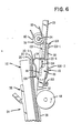
- the band 106 extends from the right side (Fig. 5) of the feeding line 52 where the leading edge 20-4 (Fig. 6) of a document 20, coming from the cupping rollers 80 and 82, contacts the band 106 to form the wave 114 as shown in Fig. 6.
- the wave 114 advances downstream towards the receiving means 54, and in the process, it moves the trailing edges 20-1, 20-2, and 20-3, for example, of the documents out of the path of the leading edge 20-4 of the incoming document 20 as shown in Fig. 6.
- the document 20 to be pocketed in the receiving means 54 in the proper order, ie. in front of the last prior document deposited therein ie. next to the stationary plate 56.
- the free-loop length of the band 106 progressively engages the back-up rib 104 as shown in the area of arrow 107.
- the back-up rib 104 is displaced from the leading edge 96 of the cupping rib 83 by a distance of 0.20 centimetre; this distance permits the free-loop length of the band 106 to slide upstream along the feeding line 52 after the wave 114 has been pushed to the downstream end by the leading edge 20-4 of the document 20. This enables the band 106 to assume the position shown in Fig. 5 in readiness for the next incoming document.
- a feature of this invention is that wave 114 in the band 106 (Fig. 6) is formed only when needed. For example, if the ends 20-1, 20-2, and 20-3-do not form a potential interference as shown in Fig. 5 by pushing the band 106 against the back-up rib 104 (Fig. 4), there will be no wave 114 formed in the band 106. Consequently, the band 106 will be pushed aside by the incoming edge 20-4 of a document 20, and the document 20 will be inserted in the receiving means 54 in a routine manner.
Landscapes
- Engineering & Computer Science (AREA)
- Mechanical Engineering (AREA)
- Separation, Sorting, Adjustment, Or Bending Of Sheets To Be Conveyed (AREA)
- Pile Receivers (AREA)
- Feeding Of Articles By Means Other Than Belts Or Rollers (AREA)
- Delivering By Means Of Belts And Rollers (AREA)
Claims (8)
Applications Claiming Priority (2)
| Application Number | Priority Date | Filing Date | Title |
|---|---|---|---|
| US06/791,492 US4640505A (en) | 1985-10-25 | 1985-10-25 | Document guide mechanism |
| US791492 | 1985-10-25 |
Publications (2)
| Publication Number | Publication Date |
|---|---|
| EP0247085A1 EP0247085A1 (de) | 1987-12-02 |
| EP0247085B1 true EP0247085B1 (de) | 1989-01-18 |
Family
ID=25153909
Family Applications (1)
| Application Number | Title | Priority Date | Filing Date |
|---|---|---|---|
| EP86906547A Expired EP0247085B1 (de) | 1985-10-25 | 1986-10-06 | Dokumentenleitanordnung |
Country Status (6)
| Country | Link |
|---|---|
| US (1) | US4640505A (de) |
| EP (1) | EP0247085B1 (de) |
| JP (1) | JPS63501148A (de) |
| CA (1) | CA1263674A (de) |
| DE (1) | DE3661815D1 (de) |
| WO (1) | WO1987002652A1 (de) |
Families Citing this family (18)
| Publication number | Priority date | Publication date | Assignee | Title |
|---|---|---|---|---|
| US4732375A (en) * | 1986-07-24 | 1988-03-22 | Cubic Western Data | Apparatus for handling strip-like media |
| US4789149A (en) * | 1987-06-23 | 1988-12-06 | Ncr Corporation | Document guide apparatus for pocketing documents |
| US5005821A (en) * | 1990-05-02 | 1991-04-09 | Xerox Corporation | Loose element sheet stacking assistance system |
| US5120047A (en) * | 1991-02-07 | 1992-06-09 | Xerox Corporation | Integral sheet stacking buckle suppressor and registration edge |
| US5199700A (en) * | 1991-09-23 | 1993-04-06 | Ncr Corporation | Document stacking apparatus |
| GB9120848D0 (en) * | 1991-10-01 | 1991-11-13 | Innovative Tech Ltd | Banknote validator |
| US5417414A (en) * | 1993-11-15 | 1995-05-23 | Pitney Bowes Inc. | Stacker improvement for handling external side seam envelopes |
| US5478064A (en) * | 1994-03-07 | 1995-12-26 | Moore Business Forms, Inc. | Delivering and stacking short grain forms |
| US6065746A (en) * | 1997-02-18 | 2000-05-23 | Unisys Corporation | Apparatus and method of automatically adjusting a document deceleration rate |
| JP3648073B2 (ja) * | 1998-05-29 | 2005-05-18 | シャープ株式会社 | シート後処理装置 |
| US6481712B1 (en) * | 2001-05-31 | 2002-11-19 | Pitney Bowes Inc. | Apparatus for preventing lead to trail edge collision of mailpieces in a sorter |
| ATE350727T1 (de) * | 2001-08-24 | 2007-01-15 | Cubic Corp | Universelle ticket-transportvorrichtung |
| US7100422B2 (en) * | 2002-05-31 | 2006-09-05 | Drs Sustainment Systems, Inc. | Systems and methods for residue collection with improved letter handling capability |
| AU2004275415A1 (en) * | 2003-09-22 | 2005-04-07 | Cubic Corporation | Mass transit bus fare box |
| US7207493B2 (en) * | 2004-12-20 | 2007-04-24 | Ncr Corporation | Document stacker apparatus and method of stacking documents |
| US7887046B2 (en) * | 2005-08-18 | 2011-02-15 | Burroughs Payment Systems, Inc. | Low-profile document feeding machine with hopper extension |
| US7887047B2 (en) * | 2005-08-18 | 2011-02-15 | Burroughs Payment Systems, Inc. | Low-profile document feeding machine with hopper floor for column forming documents |
| FR2921352B1 (fr) † | 2007-09-25 | 2010-02-12 | Solystic | Dispositif d'empilage pour envois postaux. |
Family Cites Families (10)
| Publication number | Priority date | Publication date | Assignee | Title |
|---|---|---|---|---|
| FR385872A (fr) * | 1906-12-31 | 1908-05-27 | James Nuttall | Perfectionnements dans les appareils à étendre ou empiler les feuilles de papier quittant les machines à imprimer, régler et couper, etc. |
| US3139278A (en) * | 1961-07-03 | 1964-06-30 | Burroughs Corp | Document stacking device |
| NL139834B (nl) * | 1965-05-12 | 1973-09-17 | Ibm Nederland | Afleginrichting voor documenten. |
| BE712808A (de) * | 1968-03-27 | 1968-07-31 | ||
| US3516657A (en) * | 1968-08-06 | 1970-06-23 | Moore Business Forms Inc | High capacity stackers |
| US3595565A (en) * | 1969-08-21 | 1971-07-27 | Burroughs Corp | Sheet item transport and aligning mechanism |
| US3844553A (en) * | 1973-06-04 | 1974-10-29 | Ncr Co | Document sorting control mechanism |
| US4223885A (en) * | 1978-11-13 | 1980-09-23 | Burroughs Corporation | Guide arm assembly |
| US4251000A (en) * | 1979-04-02 | 1981-02-17 | Burroughs Corporation | Front and back stacker for high speed sorter/reader apparatus |
| JPS563252A (en) * | 1979-06-14 | 1981-01-14 | Glory Ltd | Sheet accumulation and its apparatus |
-
1985
- 1985-10-25 US US06/791,492 patent/US4640505A/en not_active Expired - Lifetime
-
1986
- 1986-07-23 CA CA000514444A patent/CA1263674A/en not_active Expired
- 1986-10-06 DE DE8686906547T patent/DE3661815D1/de not_active Expired
- 1986-10-06 JP JP61505467A patent/JPS63501148A/ja active Pending
- 1986-10-06 EP EP86906547A patent/EP0247085B1/de not_active Expired
- 1986-10-06 WO PCT/US1986/002077 patent/WO1987002652A1/en not_active Ceased
Also Published As
| Publication number | Publication date |
|---|---|
| EP0247085A1 (de) | 1987-12-02 |
| WO1987002652A1 (en) | 1987-05-07 |
| US4640505A (en) | 1987-02-03 |
| DE3661815D1 (en) | 1989-02-23 |
| CA1263674A (en) | 1989-12-05 |
| JPS63501148A (ja) | 1988-04-28 |
Similar Documents
| Publication | Publication Date | Title |
|---|---|---|
| EP0247085B1 (de) | Dokumentenleitanordnung | |
| US5570877A (en) | Paper turning device for an image forming apparatus | |
| EP0509428A2 (de) | Transportvorrichtung für ein Postsortiersystem | |
| US4789150A (en) | Sheet stacking apparatus with trail edge control flaps | |
| US5476256A (en) | Disk stacker including passive sheet registration assist system | |
| US6199854B1 (en) | Document feeder with variable-speed separator | |
| EP0207425A2 (de) | Blattbestimmungs- und Zuführungsgerät | |
| US5421699A (en) | Method and apparatus for merging vertical documents with horizontal documents | |
| US5417414A (en) | Stacker improvement for handling external side seam envelopes | |
| US5449159A (en) | On edge envelope stacking apparatus with adjustable registration surface | |
| US3087724A (en) | Document delivery and stacking apparatus | |
| US5318285A (en) | Roller/guide plate assembly for ninety degree document transfer unit | |
| US5199700A (en) | Document stacking apparatus | |
| US3915447A (en) | Horizontal platen belt transport | |
| US3729188A (en) | Document stacker apparatus | |
| US3984094A (en) | Separator card retriever | |
| JPS6123148B2 (de) | ||
| US3160411A (en) | Sheet handling apparatus | |
| US5044623A (en) | Apparatus for stacking sheets | |
| EP0739844B1 (de) | Kombination Weiche, Sortier- und Stapelvorrichtung und Bogenbehalter für Druckvorrichtungen | |
| JPH0725465B2 (ja) | ソーター | |
| US3083012A (en) | Delay device for document feeding apparatus | |
| US5447303A (en) | Sheet inverter apparatus | |
| US5449163A (en) | Full productivity high performance inverter | |
| US3628787A (en) | Stacking device |
Legal Events
| Date | Code | Title | Description |
|---|---|---|---|
| PUAI | Public reference made under article 153(3) epc to a published international application that has entered the european phase |
Free format text: ORIGINAL CODE: 0009012 |
|
| AK | Designated contracting states |
Kind code of ref document: A1 Designated state(s): DE FR GB |
|
| 17P | Request for examination filed |
Effective date: 19871023 |
|
| 17Q | First examination report despatched |
Effective date: 19880527 |
|
| DET | De: translation of patent claims | ||
| GRAA | (expected) grant |
Free format text: ORIGINAL CODE: 0009210 |
|
| AK | Designated contracting states |
Kind code of ref document: B1 Designated state(s): DE FR GB |
|
| REF | Corresponds to: |
Ref document number: 3661815 Country of ref document: DE Date of ref document: 19890223 |
|
| ET | Fr: translation filed | ||
| PLBE | No opposition filed within time limit |
Free format text: ORIGINAL CODE: 0009261 |
|
| STAA | Information on the status of an ep patent application or granted ep patent |
Free format text: STATUS: NO OPPOSITION FILED WITHIN TIME LIMIT |
|
| 26N | No opposition filed | ||
| REG | Reference to a national code |
Ref country code: GB Ref legal event code: 732E |
|
| REG | Reference to a national code |
Ref country code: FR Ref legal event code: TP |
|
| PGFP | Annual fee paid to national office [announced via postgrant information from national office to epo] |
Ref country code: FR Payment date: 19940923 Year of fee payment: 9 |
|
| PGFP | Annual fee paid to national office [announced via postgrant information from national office to epo] |
Ref country code: GB Payment date: 19940928 Year of fee payment: 9 |
|
| PGFP | Annual fee paid to national office [announced via postgrant information from national office to epo] |
Ref country code: DE Payment date: 19941108 Year of fee payment: 9 |
|
| PG25 | Lapsed in a contracting state [announced via postgrant information from national office to epo] |
Ref country code: GB Effective date: 19951006 |
|
| GBPC | Gb: european patent ceased through non-payment of renewal fee |
Effective date: 19951006 |
|
| PG25 | Lapsed in a contracting state [announced via postgrant information from national office to epo] |
Ref country code: FR Effective date: 19960628 |
|
| PG25 | Lapsed in a contracting state [announced via postgrant information from national office to epo] |
Ref country code: DE Effective date: 19960702 |
|
| REG | Reference to a national code |
Ref country code: FR Ref legal event code: ST |