EP0246894B1 - Durchführung - Google Patents
Durchführung Download PDFInfo
- Publication number
- EP0246894B1 EP0246894B1 EP87304520A EP87304520A EP0246894B1 EP 0246894 B1 EP0246894 B1 EP 0246894B1 EP 87304520 A EP87304520 A EP 87304520A EP 87304520 A EP87304520 A EP 87304520A EP 0246894 B1 EP0246894 B1 EP 0246894B1
- Authority
- EP
- European Patent Office
- Prior art keywords
- feedthrough
- sealing
- duct
- supply line
- sleeve
- Prior art date
- Legal status (The legal status is an assumption and is not a legal conclusion. Google has not performed a legal analysis and makes no representation as to the accuracy of the status listed.)
- Expired - Lifetime
Links
- 238000007789 sealing Methods 0.000 claims abstract description 60
- 239000000463 material Substances 0.000 claims description 17
- 239000003566 sealing material Substances 0.000 claims description 8
- 239000002184 metal Substances 0.000 claims description 2
- 229910052751 metal Inorganic materials 0.000 claims description 2
- 238000010276 construction Methods 0.000 claims 1
- 239000000853 adhesive Substances 0.000 description 5
- 230000001070 adhesive effect Effects 0.000 description 5
- 230000008859 change Effects 0.000 description 5
- 238000009434 installation Methods 0.000 description 4
- 239000000758 substrate Substances 0.000 description 4
- 238000010438 heat treatment Methods 0.000 description 3
- 239000004831 Hot glue Substances 0.000 description 2
- 230000006835 compression Effects 0.000 description 2
- 238000007906 compression Methods 0.000 description 2
- 239000000356 contaminant Substances 0.000 description 2
- 230000007246 mechanism Effects 0.000 description 2
- 239000000565 sealant Substances 0.000 description 2
- VGGSQFUCUMXWEO-UHFFFAOYSA-N Ethene Chemical compound C=C VGGSQFUCUMXWEO-UHFFFAOYSA-N 0.000 description 1
- 239000005977 Ethylene Substances 0.000 description 1
- 241000238631 Hexapoda Species 0.000 description 1
- 239000004823 Reactive adhesive Substances 0.000 description 1
- 229910000831 Steel Inorganic materials 0.000 description 1
- 230000004913 activation Effects 0.000 description 1
- 230000004075 alteration Effects 0.000 description 1
- 238000000071 blow moulding Methods 0.000 description 1
- 229920001577 copolymer Polymers 0.000 description 1
- 229910052802 copper Inorganic materials 0.000 description 1
- 239000010949 copper Substances 0.000 description 1
- 230000003111 delayed effect Effects 0.000 description 1
- 239000000428 dust Substances 0.000 description 1
- 239000013521 mastic Substances 0.000 description 1
- 238000002844 melting Methods 0.000 description 1
- 230000008018 melting Effects 0.000 description 1
- 238000000034 method Methods 0.000 description 1
- 230000004048 modification Effects 0.000 description 1
- 238000012986 modification Methods 0.000 description 1
- -1 moisture Substances 0.000 description 1
- 238000000465 moulding Methods 0.000 description 1
- 229920000098 polyolefin Polymers 0.000 description 1
- 238000011084 recovery Methods 0.000 description 1
- 239000010959 steel Substances 0.000 description 1
- 230000001960 triggered effect Effects 0.000 description 1
Images
Classifications
-
- H—ELECTRICITY
- H02—GENERATION; CONVERSION OR DISTRIBUTION OF ELECTRIC POWER
- H02G—INSTALLATION OF ELECTRIC CABLES OR LINES, OR OF COMBINED OPTICAL AND ELECTRIC CABLES OR LINES
- H02G3/00—Installations of electric cables or lines or protective tubing therefor in or on buildings, equivalent structures or vehicles
- H02G3/22—Installations of cables or lines through walls, floors or ceilings, e.g. into buildings
-
- F—MECHANICAL ENGINEERING; LIGHTING; HEATING; WEAPONS; BLASTING
- F16—ENGINEERING ELEMENTS AND UNITS; GENERAL MEASURES FOR PRODUCING AND MAINTAINING EFFECTIVE FUNCTIONING OF MACHINES OR INSTALLATIONS; THERMAL INSULATION IN GENERAL
- F16L—PIPES; JOINTS OR FITTINGS FOR PIPES; SUPPORTS FOR PIPES, CABLES OR PROTECTIVE TUBING; MEANS FOR THERMAL INSULATION IN GENERAL
- F16L5/00—Devices for use where pipes, cables or protective tubing pass through walls or partitions
- F16L5/02—Sealing
Definitions
- the present invention relates to a feedthrough for sealing of supply lines such as pipes or cables passing through a duct in a wall, bulkhead or similar structure.
- Supply lines are often installed in environments that are prone to contaminants such as moisture, dust, insects and gasses, and therefore some form of seal has to be provided between the supply line and a duct through which it passes, to prevent ingress of the contaminants through the passage.
- feedthrough is well known in the art of passing supply lines through walls.
- a feedthrough comprises a hollow member which is preinstalled in a duct in a wall or bulkhead (which may be a wall of a building or of, for example a manhole) to provide a passage for later installation of supply lines through the wall or bulkhead.
- the present invention provides a feedthrough for providing a seal between a duct and a supply line, which comprises a sealing portion and a tubular portion, characterized in that:
- DE-A-3422793 discloses a wall feedthrough comprising a helically ribbedpipe and collars, between pairs of which collars a sealing material can be compressed to cause it to form a seal between the pipe and a duct within which the pipe lies.
- EP-A-0181945 also discloses a feedthrough having a helical outer surface.
- the feedthrough comprises two sealing portions for sealing to the inside of the duct at opposite ends thereof, the flexible portion extending between the sealing portions. More preferably the two sealing portions are both as specified above although it is envisaged that the two sealing portions may be different.
- the flexible portion of the feedthrough may comprise a length of tubing in which the wall is formed as a series of alternating radially extending ridges and valleys, hereinafter referred to as convoluted tubing. Convoluted tubing is for example preferably made by moulding, especially by blow moulding.
- the flexible portion of the feedthrough may comprise a plurality of telescopable tubes. Preferably the gap between adjacent tubes is sealable when the article is installed.
- the flexibility of the flexible portion of the feedthrough will generally be important.
- the flexible portion comprises a length of convoluted tubing, this will depend on the geometry of the convolutions, on the number of convolutions and on the nature of the material from which the flexible portion is made.
- the degree of available extensibility or compressibility is conveniently quoted as a ratio between the maximum and minimum nominal lengths of the convoluted tubing. By these nominal lengths we mean what would be the length if the convoluted tubing were extended so that the convolutions disappeared, and what would be the length if the convolutions were fully bunched together.
- the material of the convoluted tubing may of course be such that these lengths could not be achieved without the use of forces so large that the article would be damaged.
- the ratio between these nominal lengths is preferably from 2:1 to 6:1, mcre preferably about 4.5:1, since such values allow the feedthrough to be used in ducts having a wide range of lengths.
- the force required is low enough for the extension or compression to be effected easily by hand.
- the sealing portion of the feedthrough is provided with a sleeve for engaging a supply line passing through the feedthrough.
- the sleeve is dimensionally recoverable to engage the supply line.
- dimensionally recoverable is meant that the dimensions of the sleeve may be made to change substantially when subjected to an appropriate treatment. Heating is the preferred treatment.
- dimensionally recoverable articles recover towards an original shape from which they have previously been deformed but the term is also applicable to an article which adopts a new configuration even if it has not previously been deformed.
- the sleeve may be made to engage the supply line by means of a mechanical fixing tool.
- sleeve is coated internally with a layer of sealing material such as an adhesive or sealant, particularly a hot-melt adhesive.
- sealing material such as an adhesive or sealant, particularly a hot-melt adhesive.
- the feedthrough may be made re-enterable by arranging for only a selected section of the sleeve to engage the supply line.
- the sleeve when it is recoverable inwardly onto the supply line, it may be provided with a removable support to prevent recovery of part of the sleeve when the feedthrough is installed for the first time. In a subsequent installation on a new supply line, the support can be removed, and the part of the sleeve previously supported can be recovered onto the new supply line.
- the feedthrough may advantageously be provided with means for engaging the end of the duct to limit longitudinal movement of the feedthrough in the duct.
- the feedthrough may be provided at one end with a flange or other stop means which is too wide to fit into the duct, and which, in use, engages an end face of the duct such that the sealing portion of the feedthrough is correctly positioned.
- a smaller flange sized so as to pass through the duct, may be provided to be gripped at the other end of the duct, so that a sealing portion at that end of the feedthrough is correctly positioned in the duct.
- the sealing portion of the feedthrough preferably comprises an expandable tubular member of polymeric material. It is preferred that the polymeric material is heat softenable, to allow deformation thereof.
- the cross-section of the tubular member will be selected according to the cross-section of the duct, but will generally be circular. Preferred polymeric materials include olefin polymers, especially homo- and copolymers of ethylene.
- the seal between the or each sealing portion of the feedthrough and the duct may be enhanced by a layer of a sealing material such as a sealant (for example a mastic) or an adhesive (for example a heat-activatable adhesive such as a reactive adhesive, or more preferably a hot-melt adhesive) provided on the outer surface of the expandable tubular member.
- the layer of sealing material may conveniently be coated on or otherwise affixed to the exposed surface of the feedthrough.
- the sealing member may be provided with radially extending ridges to engage the internal wall of the duct when the feedthrough is installed.
- the polymeric material of the tubular member is substantially unstressed after operation of the resilient biassing means.
- substantially unstressed we therefore mean that if any stresses remain, the net force tending to displace the article from the substrate is not significant compared to the peel and/or sheer strength of any bond between the article and the substrate. Where no bond is provided, the force exerted by the mechanical member must significantly exceed any stresses in the article which would otherwise displace it from the substrate.
- the biassing means is resilient, and especially comprises one or more springs which cause or allow a radial expansion of the sealing member into sealing contact with an inside surface of the duct. It will generally be important that the biassing means may be made to change from a configuration corresponding to that of the sealing member before installation (for example a portion of a duct seal of smaller diameter) to a configuration corresponding to that of the installed sealing member (for example enlarged diameter). Although this change may be aided by heat, it must not be brought about immediately solely by heat. Thus, the sealing portion of the feedthrough may be heated away from the duct where it is to be installed without the configurational change occuring that would make it difficult or impossible to install.
- the heating is desirable, however, to soften the polymeric material to allow easy deformation once in position and/or to activate any sealing material that may be used. Therefore, the feedthrough is firstly heated, secondly placed in position, and thirdly the biassing means is operated either to allow or to cause the configurational change.
- the biassing means will have at least two rest or stable positions corresponding to the first and second configurations of the sealing member, one of which will cause the desired resiliently biassed engagement between the polymeric material of the sealing member and the supply line. This bias need not result from resilience in the biassing means, but could result from resilience in the polymeric material or in the supply line or two or more of these possibilities.
- the biassing means may be an integral part of the feedthrough in the sense that it is part of the same structure as the polymeric material, or it may be mechanically affixed or bonded thereto, or it may be separate from the polymeric material and optionally provided as a re-usable tool.
- biassing means may be by hand, for example by means of a lever which protrudes to the outside of the feedthrough.
- Other mechanisms may be employed for example an electrical release or a mechanism triggered by heat.
- melting or softening of a fusible or softenable material could allow a resiliently deformed member to relax.
- the feedthrough would be heated to soften the sealing member or to activate an adhesive, then positioned in a duct, and then an accessible part further heated to trigger the fusible or softenable release.
- a single heating step could provide the softening or adhesive activation and also activate the trigger; in this case, however, release that causes alteration of the biassing means would be delayed in order that the feedthrough could be inserted into the duct.
- Mechanical biassing means such as a casing which is expandable by a screw thread arrangement, are also envisaged.
- the biassing means will preferably be operable from outside the feedthrough. This may be achieved for example by means of a lever or other operating means extending through the supply line outlet of the feedthrough (or one of the outlets if there is more than 1). Alternatively, the operating means could pass through a hole in a side or end wall of the feedthrough provided specially for that purpose.
- Another preferred arrangement is disclosed and claimed in UK patent applicatiion no. 8609089, and provides an insert which can be positioned between the duct and the sealing portion of the feedthrough of this invention, through which the biassing means can be operated externally of the feedthrough.
- the sealing member of the feedthrough is analogous in many respects to the duct seal and to the article for sealing a substrate, which are disclosed and claimed in EP-A-170657. Reference may be made to that application for further elucidation of aspects of the sealing member.
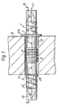
- FIG. 1 is a sectional elevation through the feedthrough positioned in a duct.
- FIG. 1 shows a feedthrough 1 positioned in a duct 3 in a wall 5.
- the feedthrough comprises two substantially identical sealing portions 7,9 joined by a flexible portion 11.
- the sealing portions 7, 9 comprise an expandable tubular member of heat-softenable polymeric material, coated with a layer of sealing material.
- the flexible portion 11 of the feedthrough comprises a length of convoluted tubing 11 by means of which the length of the feedthrough between the expandable tubular sealing portions 7, 9 can be varied.
- biassing means 13 are positioned within the expandable tubular members 7, 9, biassing means 13 are positioned.
- the biassing means take the form of springs of a metal such as steel or berylium-copper. The springs are operated from outside the feedthrough by means of levers 15, extending through the supply line outlets 17.
- the sealing portions of the feedthrough are provided with sleeves for sealing onto a supply line such as a cable or a pipe.
- the sleeves comprise heat- shrinkable polymeric material, and have a shrinkable portion 19 and a portion 21 that is held out by means of a helical support. The held out portion allows the feedthrough to be used more than once, as described above.
- the feedthrough is heated to soften the polymeric material of the sealing members, and is then passed through the duct 3, from rightto left as shown until the large flange 23 abuts the end face of the duct. The feedthrough is then either extended or compressed axially until the small flange 25 is flush with the other end face of the duct.
Landscapes
- Engineering & Computer Science (AREA)
- General Engineering & Computer Science (AREA)
- Architecture (AREA)
- Civil Engineering (AREA)
- Structural Engineering (AREA)
- Mechanical Engineering (AREA)
- Pipe Accessories (AREA)
- Duct Arrangements (AREA)
- Installation Of Indoor Wiring (AREA)
- Glass Compositions (AREA)
- Plural Heterocyclic Compounds (AREA)
- Saccharide Compounds (AREA)
- Pharmaceuticals Containing Other Organic And Inorganic Compounds (AREA)
- Rigid Pipes And Flexible Pipes (AREA)
- Joints Allowing Movement (AREA)
Claims (9)
Priority Applications (1)
| Application Number | Priority Date | Filing Date | Title |
|---|---|---|---|
| AT87304520T ATE55460T1 (de) | 1986-05-22 | 1987-05-21 | Durchfuehrung. |
Applications Claiming Priority (2)
| Application Number | Priority Date | Filing Date | Title |
|---|---|---|---|
| GB868612492A GB8612492D0 (en) | 1986-05-22 | 1986-05-22 | Feedthrough |
| GB8612492 | 1986-05-22 |
Publications (2)
| Publication Number | Publication Date |
|---|---|
| EP0246894A1 EP0246894A1 (de) | 1987-11-25 |
| EP0246894B1 true EP0246894B1 (de) | 1990-08-08 |
Family
ID=10598284
Family Applications (1)
| Application Number | Title | Priority Date | Filing Date |
|---|---|---|---|
| EP87304520A Expired - Lifetime EP0246894B1 (de) | 1986-05-22 | 1987-05-21 | Durchführung |
Country Status (6)
| Country | Link |
|---|---|
| EP (1) | EP0246894B1 (de) |
| JP (1) | JPS63125882A (de) |
| AT (1) | ATE55460T1 (de) |
| CA (1) | CA1293697C (de) |
| DE (1) | DE3764171D1 (de) |
| GB (1) | GB8612492D0 (de) |
Families Citing this family (5)
| Publication number | Priority date | Publication date | Assignee | Title |
|---|---|---|---|---|
| GB8727749D0 (en) * | 1987-11-26 | 1987-12-31 | Raychem Sa Nv | Feedthrough |
| GB8802842D0 (en) * | 1988-02-08 | 1988-03-09 | Raychem Sa Nv | Resilient device |
| DE9207293U1 (de) * | 1992-05-29 | 1992-08-13 | REHAU AG + Co, 8673 Rehau | Mauerdurchführung |
| IT1392126B1 (it) * | 2008-12-12 | 2012-02-22 | Enolgas Bonomi S P A | Scatola di contenimento di contatori di un impianto di distribuzione di fluidi |
| JP7287298B2 (ja) * | 2020-01-31 | 2023-06-06 | 積水ハウス株式会社 | 換気ダクトの施工方法及び換気構造 |
Family Cites Families (8)
| Publication number | Priority date | Publication date | Assignee | Title |
|---|---|---|---|---|
| GB1245119A (en) * | 1968-10-09 | 1971-09-08 | Raychem Corp | Improvements in building methods |
| DE1807032A1 (de) * | 1968-11-05 | 1970-05-21 | Wilhelm Emmerich | Selbstabdichtende Wanddurchfuehrungstuelle |
| US4107456A (en) * | 1976-09-27 | 1978-08-15 | General Electric Company | Electrical penetration assembly |
| DE2901268C2 (de) * | 1979-01-13 | 1981-02-05 | Werner 7922 Herbrechtingen Hauff | Wanddurchführung für Kabel, Leitungen o.dgl |
| DE3318632A1 (de) * | 1983-05-21 | 1984-11-22 | Walter Rose Gmbh & Co Kg, 5800 Hagen | Vorrichtung zur wasser- und gasdichten durchfuehrung insbesondere mehrerer kabel durch mauern od. dgl. |
| EP0154027B1 (de) * | 1984-02-28 | 1990-02-28 | Werner Hauff | Durchführung für mindestens ein elektrisches Kabel durch eine Wandöffnung |
| DE3422793A1 (de) * | 1984-06-20 | 1986-01-02 | Albert 4270 Dorsten Stewing | Vorrichtung zum abdichten von wanddurchfuehrungsrohren |
| EP0181945B1 (de) * | 1984-10-24 | 1988-09-21 | Georg Walz | Verfahren zum dichten Einbau eines rohr- oder stangenförmigen Bauteils in eine Aufnahmeöffnung eines Konstruktionskörpers |
-
1986
- 1986-05-22 GB GB868612492A patent/GB8612492D0/en active Pending
-
1987
- 1987-05-21 DE DE8787304520T patent/DE3764171D1/de not_active Expired - Lifetime
- 1987-05-21 AT AT87304520T patent/ATE55460T1/de not_active IP Right Cessation
- 1987-05-21 CA CA000537686A patent/CA1293697C/en not_active Expired - Lifetime
- 1987-05-21 EP EP87304520A patent/EP0246894B1/de not_active Expired - Lifetime
- 1987-05-22 JP JP62126857A patent/JPS63125882A/ja active Pending
Also Published As
| Publication number | Publication date |
|---|---|
| JPS63125882A (ja) | 1988-05-30 |
| ATE55460T1 (de) | 1990-08-15 |
| GB8612492D0 (en) | 1986-07-02 |
| CA1293697C (en) | 1991-12-31 |
| EP0246894A1 (de) | 1987-11-25 |
| DE3764171D1 (de) | 1990-09-13 |
Similar Documents
| Publication | Publication Date | Title |
|---|---|---|
| EP0179657B1 (de) | Abdichtungsvorrichtung | |
| US4200676A (en) | Method for joining heat-recoverable sheet material and resulting article | |
| EP0994286B1 (de) | Brandsichere Öffnung für Kabel oder Rohre | |
| GB1604444A (en) | Heatrecoverable articles | |
| US4478252A (en) | Device for enclosing objects | |
| NO823040L (no) | Gjenvinnbart lukke | |
| CA1212733A (en) | Contractible conduit sealing connector | |
| US4359502A (en) | Method for joining heat-recoverable sheet material and resulting article | |
| EP0246894B1 (de) | Durchführung | |
| CA1088434A (en) | Heat-recoverable article | |
| US4800926A (en) | Firebreak for conduits | |
| EP0094793B1 (de) | Verzweigung | |
| ES2134842T5 (es) | Abrazadera polimera termo-contraible para mangueras y tubos. | |
| EP0110705B1 (de) | Klammer für eine Abzweigung | |
| US4458104A (en) | Dimensionally recoverable articles | |
| EP0242189B1 (de) | Wanddurchführung | |
| JP3543007B2 (ja) | 外界シーリング | |
| EP0318321B1 (de) | Durchführung | |
| EP0101248A2 (de) | Flexibeler rückstellbarer rohrförmiger Gegenstand | |
| EP0967705A1 (de) | Mechanisch schrumpfbare Muffe | |
| EP0298715A2 (de) | Abdichtungsvorrichtung | |
| EP0331297B1 (de) | Expandierende Vorrichtung | |
| EP0716256A1 (de) | Eindrückbarer Dübel | |
| GB2038924A (en) | Heat Recoverable Closure Assembly and Method | |
| EP0328367A2 (de) | Durchgangsdichtung |
Legal Events
| Date | Code | Title | Description |
|---|---|---|---|
| PUAI | Public reference made under article 153(3) epc to a published international application that has entered the european phase |
Free format text: ORIGINAL CODE: 0009012 |
|
| 17P | Request for examination filed |
Effective date: 19870526 |
|
| AK | Designated contracting states |
Kind code of ref document: A1 Designated state(s): AT BE CH DE ES FR GB IT LI NL SE |
|
| 17Q | First examination report despatched |
Effective date: 19890210 |
|
| GRAA | (expected) grant |
Free format text: ORIGINAL CODE: 0009210 |
|
| AK | Designated contracting states |
Kind code of ref document: B1 Designated state(s): AT BE CH DE ES FR GB IT LI NL SE |
|
| PG25 | Lapsed in a contracting state [announced via postgrant information from national office to epo] |
Ref country code: IT Free format text: LAPSE BECAUSE OF FAILURE TO SUBMIT A TRANSLATION OF THE DESCRIPTION OR TO PAY THE FEE WITHIN THE PRESCRIBED TIME-LIMIT;WARNING: LAPSES OF ITALIAN PATENTS WITH EFFECTIVE DATE BEFORE 2007 MAY HAVE OCCURRED AT ANY TIME BEFORE 2007. THE CORRECT EFFECTIVE DATE MAY BE DIFFERENT FROM THE ONE RECORDED. Effective date: 19900808 Ref country code: LI Effective date: 19900808 Ref country code: SE Free format text: THE PATENT HAS BEEN ANNULLED BY A DECISION OF A NATIONAL AUTHORITY Effective date: 19900808 Ref country code: CH Effective date: 19900808 Ref country code: AT Effective date: 19900808 Ref country code: BE Effective date: 19900808 Ref country code: NL Effective date: 19900808 |
|
| REF | Corresponds to: |
Ref document number: 55460 Country of ref document: AT Date of ref document: 19900815 Kind code of ref document: T |
|
| REF | Corresponds to: |
Ref document number: 3764171 Country of ref document: DE Date of ref document: 19900913 |
|
| ET | Fr: translation filed | ||
| PG25 | Lapsed in a contracting state [announced via postgrant information from national office to epo] |
Ref country code: ES Free format text: LAPSE BECAUSE OF FAILURE TO SUBMIT A TRANSLATION OF THE DESCRIPTION OR TO PAY THE FEE WITHIN THE PRESCRIBED TIME-LIMIT Effective date: 19901119 |
|
| REG | Reference to a national code |
Ref country code: CH Ref legal event code: PL |
|
| NLV1 | Nl: lapsed or annulled due to failure to fulfill the requirements of art. 29p and 29m of the patents act | ||
| PLBE | No opposition filed within time limit |
Free format text: ORIGINAL CODE: 0009261 |
|
| STAA | Information on the status of an ep patent application or granted ep patent |
Free format text: STATUS: NO OPPOSITION FILED WITHIN TIME LIMIT |
|
| 26N | No opposition filed | ||
| PGFP | Annual fee paid to national office [announced via postgrant information from national office to epo] |
Ref country code: FR Payment date: 19950510 Year of fee payment: 9 Ref country code: GB Payment date: 19950510 Year of fee payment: 9 |
|
| PGFP | Annual fee paid to national office [announced via postgrant information from national office to epo] |
Ref country code: DE Payment date: 19950523 Year of fee payment: 9 |
|
| PG25 | Lapsed in a contracting state [announced via postgrant information from national office to epo] |
Ref country code: GB Effective date: 19960521 |
|
| GBPC | Gb: european patent ceased through non-payment of renewal fee |
Effective date: 19960521 |
|
| PG25 | Lapsed in a contracting state [announced via postgrant information from national office to epo] |
Ref country code: FR Effective date: 19970131 |
|
| PG25 | Lapsed in a contracting state [announced via postgrant information from national office to epo] |
Ref country code: DE Effective date: 19970201 |
|
| REG | Reference to a national code |
Ref country code: FR Ref legal event code: ST |