EP0246870B1 - Chirurgisches Klammerinstrument - Google Patents
Chirurgisches Klammerinstrument Download PDFInfo
- Publication number
- EP0246870B1 EP0246870B1 EP87304447A EP87304447A EP0246870B1 EP 0246870 B1 EP0246870 B1 EP 0246870B1 EP 87304447 A EP87304447 A EP 87304447A EP 87304447 A EP87304447 A EP 87304447A EP 0246870 B1 EP0246870 B1 EP 0246870B1
- Authority
- EP
- European Patent Office
- Prior art keywords
- frame
- actuator means
- cartridge
- surgical stapling
- stapling instrument
- Prior art date
- Legal status (The legal status is an assumption and is not a legal conclusion. Google has not performed a legal analysis and makes no representation as to the accuracy of the status listed.)
- Expired - Lifetime
Links
- 238000004140 cleaning Methods 0.000 claims description 10
- 230000015572 biosynthetic process Effects 0.000 claims description 2
- 238000005755 formation reaction Methods 0.000 claims 1
- 239000008280 blood Substances 0.000 abstract description 8
- 210000004369 blood Anatomy 0.000 abstract description 8
- 238000010276 construction Methods 0.000 description 5
- 230000000694 effects Effects 0.000 description 5
- 210000002784 stomach Anatomy 0.000 description 5
- 230000001338 necrotic effect Effects 0.000 description 2
- 230000017531 blood circulation Effects 0.000 description 1
- 238000010304 firing Methods 0.000 description 1
- 239000000463 material Substances 0.000 description 1
- RKWPZPDLTYBKCL-RVZGXXANSA-N meproscillarin Chemical compound O[C@@H]1[C@H](O)[C@@H](OC)[C@H](C)O[C@H]1O[C@@H]1C=C2CC[C@H]3[C@@]4(O)CC[C@H](C5=COC(=O)C=C5)[C@@]4(C)CC[C@@H]3[C@@]2(C)CC1 RKWPZPDLTYBKCL-RVZGXXANSA-N 0.000 description 1
- 229920003023 plastic Polymers 0.000 description 1
- 239000004033 plastic Substances 0.000 description 1
- 230000000717 retained effect Effects 0.000 description 1
- 238000003466 welding Methods 0.000 description 1
Images


Classifications
-
- A—HUMAN NECESSITIES
- A61—MEDICAL OR VETERINARY SCIENCE; HYGIENE
- A61B—DIAGNOSIS; SURGERY; IDENTIFICATION
- A61B17/00—Surgical instruments, devices or methods
- A61B17/068—Surgical staplers, e.g. containing multiple staples or clamps
- A61B17/072—Surgical staplers, e.g. containing multiple staples or clamps for applying a row of staples in a single action, e.g. the staples being applied simultaneously
Definitions
- This invention relates to a surgical stapling instrument. More particularly, this invention relates to a bariatric instrument.
- Surgical stapling instruments have been known, for example from U.S. Patent 4,383,634, to be constructed with actuating means which can be pivoted out of a frame in order to permit cleaning of the various actuator elements and the frame after use.
- the frame of the instrument has been constructed to receive a cartridge having an anvil attached thereto and which is constructed to cooperate with a reciprocable actuator means of the instrument in order to expel the staples during a translation movement.
- care must be taken that the cartridge is properly aligned in the frame prior to performing a stapling operation.
- a surgical stapling instrument as identified above, with an actuator means which can be pivoted out of a frame for cleaning, and characterised by a holder for receiving a stapling cartridge and integrally mounted on the distal end of the actuating means.
- a suitable stapling cartridge is one which has: a housing having four parallel rows of apertures on a distal side disposed in a staggered arrangement and an opening on a proximal side; a plurality of surgical staples disposed within said housing in alignment with said apertures; and means within said housing for moving said staples simultaneously from within said housing through said apertures under a pushing force applied through said opening on said proximal side.
- the rows of apertures of the housing are arranged in closely spaced relation, for example on a centerline-to-centerline equal spacing of 2mm (0.08 inches).
- the staggering and spacing of the apertures of the rows aim to provide a pattern which produces a stapled seam in the tissue, for example in a bariatric patient, which is resistant to disruption.
- the apertures are staggered so that a tortuous path through the resultant stapled seam is created.
- An embodiment of the invention makes available the possibility of stapling tissue by placing the tissue within a surgical stapling instrument and driving at least four parallel staggered and closely (preferably equally) spaced rows of surgical staples through the tissue in order to define a seam which is characterized in being resistant to disruption.
- the invention provides a surgical stapling instrument which can be readily cleaned after use and which provides for alignment for disposable stapling cartridges.
- the instrument includes a frame which has an anvil disposed at a distal end and a first actuator means connected at a proximal end to the frame for movement between a closed position coaxial with the frame and an open position away from the frame in order to permit cleaning of the frame and actuator means.
- this actuator means is reciprocally mounted within the frame when in the closed position.
- the instrument also has a holder for receiving a stapling cartridge and being integrally mounted on a distal end of the actuator means and a second actuator means connected to the frame and the first actuator means for movement between an open position away from the frame and a closed position within the frame when in the closed position thereof.
- the cartridge holder being integral with the first actuator means permits ready alignment of a cartridge received within the holder relative to the first actuator means. At the same time, the holder may be cleaned with the remainder of the first actuator means.
- the stapling instrument also may include a retaining means for retaining the first actuator means in the frame when in the closed position in order to prevent movement of the first actuator means to the open position.
- the retaining means may include a pin on the first actuator means adjacent the cartridge holder and a recess in the frame for receiving the pin therein.
- the instrument may also include a plunger rod which is reciprocally mounted in the first actuator means for expelling staples from a cartridge mounted in the holder.
- This plunger is aligned with the second actuator means in order to be moved by the second actuator means, for example, by a handle pivotally mounted in the frame, in order to expel staples from a cartridge in the holder against the anvil.
- the construction of the anvil mirrors the pattern of apertures in a stapling cartridge which is to be mounted in the cartridge holder so as to effect stapling of tissue.
- the second actuator means When the instrument is to be used, for example, for bariatric stapling, the second actuator means is pivoted to the open position while the first actuator means is disposed in a closed position relative to the frame. At this time, the pin of the retaining means is disposed in the recess provided for the pin in the frame so that the first actuator means cannot pivot from the frame into an open position.
- a stapling cartridge is inserted into the cartridge holder if not previously inserted. Thereafter, the tissue to be stapled in positioned between the anvil and the stapling cartridge.
- a suitable alignment and guide pin as is known, is then passed through the cartridge and the frame so that the cartridge may be guided between the pin and, for example a runner or rail on the frame at an opposite end of the cartridge.
- the second actuator assembly is then pivoted into a closed position. This causes the first actuator means and the cartridge holder to move so as to clamp the tissue to be stapled between the anvil and the base of the stapling cartridge. Next, the handle is then pivoted to cause the plunger rod to expel the staples through the tissue and against the anvil to form a stapled seam within the tissue.
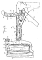
- the surgical stapling instrument 10 is constructed, for example for use in the bariatric treatment of obese patients.
- the instrument 10 includes a frame 11 which defines an elongated channel-shaped portion 12, a hand grip portion 13 at the proximal end and a U-shaped extension 14 at the distal end.
- This U-shaped extension 14 includes a distal leg 15 on which an anvil 16 is integrally formed.
- the frame includes a cleft 17 formed by a pair of outstanding arms for receiving an alignment and guide pin unit 18.
- the alignment and guide pin unit 18 is of generally known construction and includes a tubular collar 19 which can be snap fitted in place between the arms of the clift 17 while being freely rotatable therein.
- the unit 18 includes a pin 20 which is slidable within the collar 19 and which has a threaded distal end 21 and carries a knurled knob 22 at the proximal end.
- the pin 20 also has a circumferential recess (not shown) near the threaded end which receives a spring clip (not shown) which is internally mounted in the collar 19.
- the threaded distal end 21 cooperates with a threaded aperture 23 in the distal leg 15 of the U-shaped extension 14 of the frame 11 when the pin 20 is moved forward.
- the instrument 10 includes a pair of actuator means 24, 25 and a handle 26 which are articulated within the frame 11 for movement relative to and with each other.
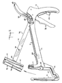
- the first or distal actuator means 24 is connected at the proximal end to the frame 11 for movement between a closed position as shown in Fig 1 coaxial with the frame 11 and an open position as shown in Fig. 7 away from the frame 11 in order to permit cleaning.
- the distal actuator means 24 includes an elongated channel shaped bar 27 which is articulated by a joint 28 at a proximal end to the frame 11 and proximal actuator means 25 and which carries a stapling cartridge holder 28 which is integrally mounted at the distal end.
- a plunger rod 30 is disposed internally of the channel shape bar 27 as shown in Fig. 3.
- This plunger rod 30 is biased by a spring 31 in he proximal direction against a stop pin 32 which is fixed within the bar 27. As indicated in Fig. 3, the plunger rod 30 has an enlarged head 33 which extends into an opening at the proximal end of the cartridge holder 29.
- the channel shaped bar 27 also carries a pin 34 which extends on opposite sides for reception within L-shaped guide slots 35 in the frame as indicated in Fig. 7.
- the cartridge holder 29 is formed of a U-shaped member having a pair of arms 36 and a base 37 which is secured as a welding to the channel shaped bar 27.
- a stapling cartridge 38 includes a housing 39 which has outstanding tabs 40, 41 which are received in elongated guide recesses 42 of the arms 36 of the holder 29.
- each guide recess 42 tapers to a narrowed section at a forward end to receive tabs 40 of relatively small size while the rear ends of the recesses 42 receive enlarged tabs 41, for example of plastics material, which are provided on an end cap 43 of the cartridge 38.
- the tabs 40, 41 serve to align the cartridge 38 within the holder 29.
- the cartridge 38 also includes four parallel rows 44 of apertures on a distal side which are disposed in staggered arrangement as well as in a closely spaced relation, for example on a centerline-to-centerline spacing of 2mm (0.08 inches).
- the cartridge 38 also includes a plurality of staples 45 (see Fig. 4) which are disposed within the housing 39 in known manner.
- a means for example in the form of a pusher bar 46 (see Fig. 4) is disposed in the housing 39 in order to move the staples 45 through the apertures 44.
- a suitable opening (not shown) is provided in the proximal side of the housing 39 so as to permit entry of the enlarged head 33 of the plunger rod 30.
- the anvil 16 of the frame 11 is also provided with matching recesses for the apertures 44 to provide staple-clinching formation in known manner.
- the second or proximal actuator means 25 is constructed in similar manner to that as described in U.S. Patent 4,383,634 Figs. 3 and 14.
- the proximal actuator means 25 is articulated to the joint 28 at the distal end in order to pivot between an opened position as shown in Fig. 3 and a closed position as shown in Fig. 4.
- the proximal actuator means 25 includes a curved portion 47 which is provided with knurling 48 at the proximal end for gripping purposes.
- the second actuator means 25 is articulated for reciprocating the distal actuator means 24, as indicated in Fig.
- the second actuator means 25 has a plunger 49 provided with a recess 50 to receive a detent 51 of the handle 26 to move forwardly when the handle 26 is pivoted clockwise as viewed in Fig. 4.
- a suitable spring 52 is provided to bias the plunger 49 in the proximal direction. When pushed forwardly, the plunger 49 abuts the plunger rod 30 of the distal actuator means in order to push the plunger rod 30 forwardly.
- articulated joint 28 between the actuator means 24, 25 and the handle 26 is of generally known construction, for example, as described in US. Pat. 4,383,634.
- a suitable safety latch 53 is provided in the frame 11 to prevent accidental pivoting of the handle 26.
- a retaining means is provided for retaining the distal actuator means 24 in the frame 11 when in the closed position in order to prevent movement of the actuator means 24 to the open position.
- the retaining means includes a pin 54 which is integrally connected to the bar 27 of the actuator means 24 adjacent to the cartridge holder 29 as well as a recess 55 in one side of the bar 27.
- the cartridge holder 29 can be manually grasped so that the pin 54 passes freely over the cleft 17 and is positioned in front of the recess 55. Thereafter, a slight movement of the cartridge holder 29 and bar 27 is in proximal direction is able to seat the pin 54 within the recess 55. During pivoting of the bar 27, the pin 34 enters the recesses 35 in the frame 11.
- the distal actuator means 24 cannot be readily pivoted into the open position.
- placement of the pin 54 in the recess 55 aligns the cartridge holder 29 relative to the anvil 16.
- the cartridge is also aligned with the anvil 16.
- the stapling cartridge 38 is provided, in known manner, with a pair of outwardly extending flanges 56 at the forward end which cooperate with a rail 57 on the U-shaped extension 14 of the frame 11 such that the flanges center the cartridge 38 on the rail 57.
- the flanges 56 and rail 157 serve to guide the cartridge 38 during a stapling operation.
- the distal actuator means 24 is placed in the closed position with the pin 54 in the recess 55 as indicated in Fig. 3.
- a stapling cartridge 38 is slid into the arms of the holder 29 with the flanges 56 engaging against the sides of the rail 57 of the frame 11.
- the cartridge 38 is aligned with the anvil 16.
- the alignment and guide pin unit 18 is fitted into place.
- the pin 20 is passed through a passage 58 at the rear end of the cartridge 38 and threaded into the threaded aperture 23 in the distal leg 15 of the frame extensions 14. Thereafter, the cartridge 38 can be guided by the rail 57 and the pin 20.
- the proximal actuator means 25 is pivoted from the open position of Fig. 3 into the closed position. This causes the forward movement of the first actuator means 24 including the cartridge holder 29 and the cartridge 38. At this time, the tissue to be stapled is clamped between the distal side of the cartridge 38 and the anvil 16.
- the handle 26 is pivoted counter-clockwise as indicated in Fig. 5 so that the plunger rod 30 is moved into the cartridge housing 39 to push the staples 45 outwardly through the tissue T and against the anvil 16 for clinching in known manner.
- the handle 26 is released and returned via a spring 59 to the initial position.
- the proximal actuator means 25 is then pivoted into the open position shown in Fig. 3, the alignment pin 20 is unthreaded from the distal leg 15 and retracted, and the instrument 10 removed from the patient. At that time, the emptied cartridge 38 can be disposed of and the instrument 10 subjected to cleaning.
- the second actuator means 25 is disposed in the open position and the distal actuator means 24 manipulated forwardly so as to remove the pin 54 from the recess 55 so that the actuator means 24 can be moved to the open position for cleaning purposes.
- the tissue T which has been stapled has a seam 60 which is formed by the four parallel rows of staples 45 in a pattern so as to prevent the passage of blood through the seam 60.
- the stream would initially pass between two staples 45 in the first row.
- the stream Upon reaching the facing staple in the second row, the stream would divert, for examaple upwardly as viewed in Fig. 2.
- the blood Upon reaching the next gap, the blood would tend to pass through until reaching a staple in the third row.
- the blood stream would again be diverted upwardly or downwardly, as viewed in Fig. 2, until reaching the next gap. Because of the contorted path which the blood stream would have to follow through the seam 60, it has been found that the blood does not bleed through as may be the case if there were only two rows of staples.
- the invention thus provides an instrument for forming stapled seems in tissue in a manner to resist disruption.
- the surgical instrument is able to form a seam of four parallel equispaced rows of surgical staples.
- the remaining three rows of staples provide a secure seam.
- the four rows of staples can be ejected by a single instrument, the overall time required to form the seam is reduced as compared with previously known instruments.
- the invention provides a stapling instrument in which a disposable cartridge can be inserted and aligned in a relatively simple manner relative to an anvil.
- the invention provides an instrument which can be readily cleaned without being disassembled.
- the invention further provides a surgical stapling instrument which has an integrated disposable cartridge holder which permits easy alignment of a stapling cartridge while also facilitating cleaning of the cartridge holder with the instrument.
Landscapes
- Health & Medical Sciences (AREA)
- Life Sciences & Earth Sciences (AREA)
- Surgery (AREA)
- Molecular Biology (AREA)
- Engineering & Computer Science (AREA)
- Biomedical Technology (AREA)
- Heart & Thoracic Surgery (AREA)
- Medical Informatics (AREA)
- Nuclear Medicine, Radiotherapy & Molecular Imaging (AREA)
- Animal Behavior & Ethology (AREA)
- General Health & Medical Sciences (AREA)
- Public Health (AREA)
- Veterinary Medicine (AREA)
- Surgical Instruments (AREA)
- Materials For Medical Uses (AREA)
- Gripping Jigs, Holding Jigs, And Positioning Jigs (AREA)
Claims (9)
- Ein chirurgisches Klammerinstrument (10) umfassend:
einen Rahmen (11) mit einem an einem distalen Ende angeordneten Amboß (16);
eine an einem proximalen Ende mit dem besagten Rahmen verbundene erste Bedienungsvorrichtung (24), die zwischen einer geschlossenen, mit dem besagten Rahmen koaxialen Stellung und einer offenen Stellung weg von dem besagten Rahmen bewegbar ist, um ein Reinigen des besagten Rahmens und der besagten Bedienungsvorrichtung zu erlauben, wobei die besagte Bedienungsvorrichtung in der besagten geschlossenen Stellung innerhalb des besagten Rahmens hin- und herbewegbar angebracht ist; und
eine mit dem besagten Rahmen und der besagten ersten Bedienungsvorrichtung verbundene zweite Bedienungsvorrichtung (25), die zwischen einer geöffneten Stellung weg von dem besagten Rahmen und einer geschlossenen Stellung innerhalb des besagten Rahmens bewegbar ist, um die besagte erste Bedienungsvorrichtung innerhalb des besagten Rahmens hin und her zu bewegen, wenn sie sich in der besagten geschlossenen Stellung derselben befindet;
und gekennzeichnet durch:
eine auf dem distalen Ende der besagten ersten Bedienungsvorrichtung und als Einheit mit diesem angebrachte Halterung (29) zum Aufnehmen einer Klammerpatrone. - Ein chirurgisches Klammerinstrument nach Anspruch 1, dadurch gekennzeichnet, daß es weiter eine Rückhaltevorrichtung (18) umfaßt, um die besagte erste Bedienungsvorrichtung in dem besagten Rahmen in der besagten geschlossenen Stellung derselben zurückzuhalten, um eine Bewegung der besagten ersten Bedienungsvorrichtung in die besagte geöffnete Stellung derselben zu verhindern.
- Ein chirurgisches Klammerinstrument nach Anspruch 2, dadurch gekennzeichnet, daß die besagte Rückhaltevorrichtung einen nahe der besagten Halterung zur Aufnahme einer Klammerpatrone anzubringenden Stift (20) und eine Ausnehmung (17) in dem besagtem Rahmen umschließt, um den besagten Stift darin aufzunehmen.
- Ein chirurgisches Klammerinstrument nach Anspruch 1, 2 oder 3, dadurch gekennzeichnet, daß es weiter umschließt:
eine Druckstange (30), die in der besagten ersten Bedienungsvorrichtung hin- und herbewegbar angebracht ist, um Klammern (45) aus einer in der besagten Halterung angebrachten Patrone (38) auszustoßen, und die mit der besagten zweiten Bedienungsvorrichtung ausgerichtet ist;
einen in dem besagten Rahmen schwenkbar angebrachten Griff (26), um die besagte zweite Bedienungsvorrichtung gegen die besagte Druckstange zu bewegen, um Klammern aus einer Patrone in der besagten Halterung gegen den besagten Amboß auszustoßen. - Ein chirurgisches Klammerinstrument nach einem beliebigen der vorhergehenden Ansprüche, dadurch gekennzeichnet, daß es weiter einen Bolzen (54) auf der besagten ersten Bedienungsvorrichtung nahe der besagten Patronenhalterung und eine Ausnehmung (55) in dem besagten Rahmen einschließt, um den besagten Bolzen darin aufzunehmen, um eine Bewegung der besagten ersten Bedienungsvorrichtung in die besagte geöffnete Stellung derselben zu verhindern.
- Ein chirurgisches Klammerinstrument nach einem beliebigen der vorhergehenden Ansprüche, dadurch gekennzeichnet, daß der Amboß Reihen von Einrichtungen zum Zusammenpressen von Klammern einschließt, die mit einem Abstand von 2 mm (0,08 inches) von Mittellinie zu Mittellinie angeordnet sind.
- Ein chirurgisches Klammerinstrument nach einem beliebigen der vorhergehenden Ansprüche, dadurch gekennzeichnet, daß es weiter eine Klammerpatrone (38) umfaßt, umfassend ein Gehäuse (39) mit vier parallelen Reihen (44) von Öffnungen auf einer distalen Seite, die versetzt angeordnet sind, und mit einer Öffnung auf einer proximalen Seite, sowie eine Mehrzahl von innerhalb des besagten Gehäuses mit den besagten Öffnungen fluchtend angeordnete chirurgische Klammern (45).
- Ein chirurgisches Klammerinstrument (10) nach Anspruch 7, dadurch gekennzeichnet, daß es weiter eine Vorrichtung (46) innerhalb des besagten Gehäuses umfaßt, um die besagten Klammern unter einer durch die besagte Öffnung auf der besagten proximalen Seite aufgebrachten Druckkraft gleichzeitig von innerhalb des besagten Gehäuses durch die besagten Öffnungen zu bewegen.
- Ein chirurgisches Klammerinstrument (10) nach Anspruch 7 oder 8, dadurch gekennzeichnet, daß die besagten Reihen in einer eng nebeneinanderliegenden versetzten Beziehung zueinander angeordnet sind.
Priority Applications (1)
| Application Number | Priority Date | Filing Date | Title |
|---|---|---|---|
| AT87304447T ATE92297T1 (de) | 1986-05-23 | 1987-05-19 | Chirurgisches klammerinstrument. |
Applications Claiming Priority (2)
| Application Number | Priority Date | Filing Date | Title |
|---|---|---|---|
| US06/866,800 US4802614A (en) | 1986-05-23 | 1986-05-23 | Surgical stapling instrument and cartridge |
| US866800 | 1986-05-23 |
Publications (3)
| Publication Number | Publication Date |
|---|---|
| EP0246870A2 EP0246870A2 (de) | 1987-11-25 |
| EP0246870A3 EP0246870A3 (en) | 1988-03-02 |
| EP0246870B1 true EP0246870B1 (de) | 1993-08-04 |
Family
ID=25348443
Family Applications (1)
| Application Number | Title | Priority Date | Filing Date |
|---|---|---|---|
| EP87304447A Expired - Lifetime EP0246870B1 (de) | 1986-05-23 | 1987-05-19 | Chirurgisches Klammerinstrument |
Country Status (5)
| Country | Link |
|---|---|
| US (1) | US4802614A (de) |
| EP (1) | EP0246870B1 (de) |
| AT (1) | ATE92297T1 (de) |
| DE (1) | DE3786833T2 (de) |
| ES (1) | ES2042562T3 (de) |
Families Citing this family (59)
| Publication number | Priority date | Publication date | Assignee | Title |
|---|---|---|---|---|
| US4930503A (en) * | 1987-06-11 | 1990-06-05 | Pruitt J Crayton | Stapling process and device for use on the mesenteries of the abdomen |
| US5027834A (en) * | 1987-06-11 | 1991-07-02 | United States Surgical Corporation | Stapling process for use on the mesenteries of the abdomen |
| US4848637A (en) * | 1987-06-11 | 1989-07-18 | Pruitt J Crayton | Staple device for use on the mesenteries of the abdomen |
| CA2052176A1 (en) * | 1990-10-05 | 1992-04-06 | Daniel P. Rodak | Controlled closure mechanism |
| CA2075141C (en) * | 1991-10-17 | 1998-06-30 | Donald A. Morin | Anvil for surgical staplers |
| US5327914A (en) * | 1992-09-02 | 1994-07-12 | Shlain Leonard M | Method and devices for use in surgical gastroplastic procedure |
| US5439155A (en) * | 1993-10-07 | 1995-08-08 | United States Surgical Corporation | Cartridge for surgical fastener applying apparatus |
| US5651491A (en) * | 1995-10-27 | 1997-07-29 | United States Surgical Corporation | Surgical stapler having interchangeable loading units |
| US5820009A (en) * | 1996-02-20 | 1998-10-13 | Richard-Allan Medical Industries, Inc. | Articulated surgical instrument with improved jaw closure mechanism |
| US5911352A (en) * | 1996-12-17 | 1999-06-15 | United States Surgical Corporation | Surgical stapling apparatus |
| US6805273B2 (en) * | 2002-11-04 | 2004-10-19 | Federico Bilotti | Surgical stapling instrument |
| US6817508B1 (en) | 2000-10-13 | 2004-11-16 | Tyco Healthcare Group, Lp | Surgical stapling device |
| US7407076B2 (en) * | 2000-10-13 | 2008-08-05 | Tyco Healthcare Group Lp | Surgical stapling device |
| RU2242183C2 (ru) * | 2002-10-14 | 2004-12-20 | Пронин Василий Михайлович | Сшиватель-ушиватель органов и тканей |
| US20050143759A1 (en) * | 2003-12-30 | 2005-06-30 | Kelly William D. | Curved cutter stapler shaped for male pelvis |
| US20060122635A1 (en) * | 2004-12-03 | 2006-06-08 | Naegeli Chad D | Storage system for bioabsorbable fasteners |
| US8021375B2 (en) * | 2008-04-21 | 2011-09-20 | Conmed Corporation | Surgical clip applicator |
| CA2665017A1 (en) * | 2008-05-05 | 2009-11-05 | Tyco Healthcare Group Lp | Surgical instrument with sequential clamping and cutting |
| US8424738B2 (en) * | 2008-06-04 | 2013-04-23 | Covidien Lp | Attachable clamp for surgical stapler |
| US8016176B2 (en) | 2008-06-04 | 2011-09-13 | Tyco Healthcare Group, Lp | Surgical stapling instrument with independent sequential firing |
| US8070038B2 (en) | 2008-10-10 | 2011-12-06 | Tyco Healthcare Group, Lp | Surgical instrument with pivotable jaw member |
| US8353436B2 (en) | 2009-05-06 | 2013-01-15 | Covidien Lp | Pin locking mechanism for a surgical instrument |
| US8328064B2 (en) | 2009-05-06 | 2012-12-11 | Covidien Lp | Pin locking mechanism for a surgical instrument |
| US9023069B2 (en) | 2009-05-18 | 2015-05-05 | Covidien Lp | Attachable clamp for use with surgical instruments |
| US8245897B2 (en) * | 2010-01-26 | 2012-08-21 | Zakease Surgical Inc. | Stapling apparatus for performing anastomosis on hollow organs |
| US8827137B2 (en) * | 2010-03-25 | 2014-09-09 | Covidien Lp | Pin alignment assembly for surgical stapler |
| CN102835982B (zh) * | 2011-06-21 | 2016-11-02 | 伊西康内外科公司 | 具有多功能保持销子组件的线性缝合器 |
| EP2770921B1 (de) | 2011-10-26 | 2019-02-27 | Intuitive Surgical Operations, Inc. | Chirurgisches instrument mit integrierter messerklinge |
| EP2779921B1 (de) | 2011-11-15 | 2019-03-27 | Intuitive Surgical Operations, Inc. | Chirurgisches instrument mit verstaubarer messerklinge |
| US9498215B2 (en) * | 2012-12-31 | 2016-11-22 | Intuitive Surgical Operations, Inc. | Surgical staple cartridge with enhanced knife clearance |
| RU2663489C2 (ru) * | 2013-02-08 | 2018-08-06 | Этикон Эндо-Серджери, Инк. | Кассета со скобами, содержащая крышку с возможностью высвобождения |
| US8617182B1 (en) * | 2013-02-18 | 2013-12-31 | Sinn Rx, LLC | Surgical staple remover |
| US8579917B1 (en) * | 2013-02-18 | 2013-11-12 | Sinn Rx, LLC | Surgical staple remover with removable front end |
| JP6484341B2 (ja) | 2014-12-25 | 2019-03-13 | コヴィディエン リミテッド パートナーシップ | 外科用ステープル留めデバイス |
| US9775611B2 (en) | 2015-01-06 | 2017-10-03 | Covidien Lp | Clam shell surgical stapling loading unit |
| US9855040B2 (en) | 2015-03-04 | 2018-01-02 | Covidien Lp | Surgical stapling loading unit having articulating jaws |
| US10575848B2 (en) * | 2015-12-31 | 2020-03-03 | Ethicon Llc | Surgical stapler with fixed jaw support pin |
| US10561474B2 (en) | 2015-12-31 | 2020-02-18 | Ethicon Llc | Surgical stapler with end of stroke indicator |
| US10045780B2 (en) | 2015-12-31 | 2018-08-14 | Ethicon Llc | Method of applying staples in lower anterior bowel resection |
| US10610219B2 (en) | 2015-12-31 | 2020-04-07 | Ethicon Llc | Surgical stapler with curved outer surface on anvil |
| US10258334B2 (en) | 2015-12-31 | 2019-04-16 | Ethicon Llc | Surgical stapler with variable height drivers for uniform staple formation |
| US10285693B2 (en) | 2015-12-31 | 2019-05-14 | Ethicon Llc | Surgical stapler with locking translatable pin |
| USD814632S1 (en) | 2016-10-21 | 2018-04-03 | Covidien Lp | Staple cartridge |
| AU2017258826A1 (en) | 2016-12-02 | 2018-06-21 | Covidien Lp | Surgical stapling instrument with curved end effector |
| US10993714B2 (en) | 2017-11-28 | 2021-05-04 | Covidien Lp | Surgical stapling instrument and associated trigger mechanisms |
| US10945730B2 (en) | 2018-06-25 | 2021-03-16 | Covidien Lp | Stapling device with selectively advanceable alignment pin |
| AU2019460295A1 (en) | 2019-08-02 | 2022-03-24 | Covidien Lp | Surgical stapling device with curved tool assembly |
| JP2023509271A (ja) | 2019-11-01 | 2023-03-08 | コヴィディエン リミテッド パートナーシップ | ナイフブレード係止を有する外科用ステープル留めデバイス |
| US11857185B2 (en) | 2019-12-18 | 2024-01-02 | Covidien Lp | Surgical stapling device with shipping cap |
| CA3169731A1 (en) | 2020-02-03 | 2021-08-12 | Coviden Lp | Tissue guide for curved end effectors |
| EP4103071A4 (de) | 2020-02-14 | 2023-11-01 | Covidien LP | Chirurgische klammervorrichtung mit einweg-schneidplatte |
| CN115151195A (zh) | 2020-02-27 | 2022-10-04 | 柯惠有限合伙公司 | 带可重装钉仓的手术钉合装置 |
| CN115175624A (zh) | 2020-02-28 | 2022-10-11 | 柯惠有限合伙公司 | 具有可伸缩刀组合件的钉仓 |
| US11744584B2 (en) | 2020-06-09 | 2023-09-05 | Covidien Lp | Alignment pin assembly for surgical stapler |
| WO2022126471A1 (en) | 2020-12-17 | 2022-06-23 | Covidien Lp | Stapling device with curved end effector |
| CN117062573A (zh) | 2021-02-25 | 2023-11-14 | 柯惠有限合伙公司 | 减小偏转的砧座组件 |
| CN117062572A (zh) | 2021-03-30 | 2023-11-14 | 柯惠有限合伙公司 | 包含装载单元对准指示器的外科缝合装置 |
| WO2022233014A1 (en) | 2021-05-07 | 2022-11-10 | Covidien Lp | End effector for surgical stapling device |
| US12268390B2 (en) | 2021-07-19 | 2025-04-08 | Covidien Lp | Stapling device with replaceable cartridge module |
Family Cites Families (12)
| Publication number | Priority date | Publication date | Assignee | Title |
|---|---|---|---|---|
| US3252643A (en) * | 1962-12-24 | 1966-05-24 | Strekopytov Alexey Alexcevich | Instrument for suturing living tissue |
| US3275211A (en) * | 1965-05-10 | 1966-09-27 | United States Surgical Corp | Surgical stapler with replaceable cartridge |
| US3494533A (en) * | 1966-10-10 | 1970-02-10 | United States Surgical Corp | Surgical stapler for stitching body organs |
| GB1374002A (en) * | 1971-05-03 | 1974-11-13 | Vnii Khirurgicheskoi Apparatur | Surgical instrument for suturing tissues and organs with metal staples |
| SU886900A1 (ru) * | 1979-03-26 | 1981-12-07 | Всесоюзный научно-исследовательский и испытательный институт медицинской техники | Хирургический сшивающий аппарат дл наложени линейных швов |
| AU534210B2 (en) * | 1980-02-05 | 1984-01-12 | United States Surgical Corporation | Surgical staples |
| US4402444A (en) * | 1981-04-20 | 1983-09-06 | United States Surgical Corporation | Surgical stapling instrument with automatic frame reinforcement |
| US4383634A (en) * | 1981-05-26 | 1983-05-17 | United States Surgical Corporation | Surgical stapler apparatus with pivotally mounted actuator assemblies |
| US4470533A (en) * | 1982-08-13 | 1984-09-11 | Ethicon, Inc. | Surgical instrument for suturing tissues and organs |
| FR2544608B1 (fr) * | 1983-04-22 | 1986-01-03 | Beillard Renaud | Chargeur d'agrafes amovible pour sutures medicales |
| US4606345A (en) * | 1984-07-16 | 1986-08-19 | Ethicon, Inc. | Surgical instrument for applying two-piece fasteners comprising U-shaped staples and frictionally held receivers (Case II) |
| US4573622A (en) * | 1984-10-19 | 1986-03-04 | United States Surgical Corporation | Surgical fastener applying apparatus with variable fastener arrays |
-
1986
- 1986-05-23 US US06/866,800 patent/US4802614A/en not_active Expired - Lifetime
-
1987
- 1987-05-19 AT AT87304447T patent/ATE92297T1/de active
- 1987-05-19 DE DE87304447T patent/DE3786833T2/de not_active Expired - Lifetime
- 1987-05-19 EP EP87304447A patent/EP0246870B1/de not_active Expired - Lifetime
- 1987-05-19 ES ES87304447T patent/ES2042562T3/es not_active Expired - Lifetime
Also Published As
| Publication number | Publication date |
|---|---|
| DE3786833T2 (de) | 1993-12-09 |
| EP0246870A2 (de) | 1987-11-25 |
| US4802614A (en) | 1989-02-07 |
| ES2042562T3 (es) | 1993-12-16 |
| DE3786833D1 (de) | 1993-09-09 |
| ATE92297T1 (de) | 1993-08-15 |
| EP0246870A3 (en) | 1988-03-02 |
Similar Documents
| Publication | Publication Date | Title |
|---|---|---|
| EP0246870B1 (de) | Chirurgisches Klammerinstrument | |
| US11337696B2 (en) | Surgical stapling device | |
| CA1220687A (en) | Disposable linear surgical stapler | |
| US5893506A (en) | Surgical stapler with anvil sensor and lockout | |
| CA2563147C (en) | Surgical stapling device | |
| EP0105797B1 (de) | Verfahren und Vorrichtung zum Anbringen von Klammern, die Klammern und eine Reihe von Klammern dafür | |
| US5342391A (en) | Cleanable endoscopic surgical instrument | |
| US5170925A (en) | Laparoscopic stapler with knife means | |
| US5413267A (en) | Surgical stapler with spent cartridge sensing and lockout means | |
| CA2068581C (en) | Surgical stapler with spent cartridge sensing and lockout means | |
| CN113518591A (zh) | 具有用于改变组织压缩的倾斜钉平台的外科缝合器 | |
| EP1671593A1 (de) | Zusammenbau von chirurgischem Klammerwerkzeug | |
| AU2002362750A1 (en) | Surgical stapling device | |
| JPH012639A (ja) | 外科手術用クリップの取付け装置 | |
| MXPA05000218A (es) | Engrapadora cortadora curva configurada para pelvis masculina. | |
| EP3586769B1 (de) | Heftvorrichtung mit selektiv ausfahrbarem ausrichtungsstift | |
| CA1280330C (en) | Surgical stapling instrument and cartridge |
Legal Events
| Date | Code | Title | Description |
|---|---|---|---|
| PUAI | Public reference made under article 153(3) epc to a published international application that has entered the european phase |
Free format text: ORIGINAL CODE: 0009012 |
|
| AK | Designated contracting states |
Kind code of ref document: A2 Designated state(s): AT BE DE ES FR GB IT LU NL |
|
| PUAL | Search report despatched |
Free format text: ORIGINAL CODE: 0009013 |
|
| AK | Designated contracting states |
Kind code of ref document: A3 Designated state(s): AT BE DE ES FR GB IT LU NL |
|
| 17P | Request for examination filed |
Effective date: 19880822 |
|
| 17Q | First examination report despatched |
Effective date: 19910716 |
|
| GRAA | (expected) grant |
Free format text: ORIGINAL CODE: 0009210 |
|
| AK | Designated contracting states |
Kind code of ref document: B1 Designated state(s): AT BE DE ES FR GB IT LU NL |
|
| PG25 | Lapsed in a contracting state [announced via postgrant information from national office to epo] |
Ref country code: NL Effective date: 19930804 Ref country code: BE Effective date: 19930804 Ref country code: AT Effective date: 19930804 |
|
| REF | Corresponds to: |
Ref document number: 92297 Country of ref document: AT Date of ref document: 19930815 Kind code of ref document: T |
|
| REF | Corresponds to: |
Ref document number: 3786833 Country of ref document: DE Date of ref document: 19930909 |
|
| ITF | It: translation for a ep patent filed | ||
| ET | Fr: translation filed | ||
| REG | Reference to a national code |
Ref country code: ES Ref legal event code: FG2A Ref document number: 2042562 Country of ref document: ES Kind code of ref document: T3 |
|
| NLV1 | Nl: lapsed or annulled due to failure to fulfill the requirements of art. 29p and 29m of the patents act | ||
| PG25 | Lapsed in a contracting state [announced via postgrant information from national office to epo] |
Ref country code: LU Free format text: LAPSE BECAUSE OF NON-PAYMENT OF DUE FEES Effective date: 19940531 |
|
| PLBE | No opposition filed within time limit |
Free format text: ORIGINAL CODE: 0009261 |
|
| STAA | Information on the status of an ep patent application or granted ep patent |
Free format text: STATUS: NO OPPOSITION FILED WITHIN TIME LIMIT |
|
| 26N | No opposition filed | ||
| REG | Reference to a national code |
Ref country code: GB Ref legal event code: IF02 |
|
| PGFP | Annual fee paid to national office [announced via postgrant information from national office to epo] |
Ref country code: FR Payment date: 20060517 Year of fee payment: 20 |
|
| PGFP | Annual fee paid to national office [announced via postgrant information from national office to epo] |
Ref country code: GB Payment date: 20060525 Year of fee payment: 20 |
|
| PGFP | Annual fee paid to national office [announced via postgrant information from national office to epo] |
Ref country code: ES Payment date: 20060526 Year of fee payment: 20 |
|
| PGFP | Annual fee paid to national office [announced via postgrant information from national office to epo] |
Ref country code: IT Payment date: 20060531 Year of fee payment: 20 |
|
| PGFP | Annual fee paid to national office [announced via postgrant information from national office to epo] |
Ref country code: DE Payment date: 20060630 Year of fee payment: 20 |
|
| PG25 | Lapsed in a contracting state [announced via postgrant information from national office to epo] |
Ref country code: ES Free format text: LAPSE BECAUSE OF EXPIRATION OF PROTECTION Effective date: 20070521 |
|
| REG | Reference to a national code |
Ref country code: GB Ref legal event code: PE20 |
|
| REG | Reference to a national code |
Ref country code: ES Ref legal event code: FD2A Effective date: 20070521 |
|
| PG25 | Lapsed in a contracting state [announced via postgrant information from national office to epo] |
Ref country code: GB Free format text: LAPSE BECAUSE OF EXPIRATION OF PROTECTION Effective date: 20070518 |