EP0246522A2 - Commande de vitesse - Google Patents
Commande de vitesse Download PDFInfo
- Publication number
- EP0246522A2 EP0246522A2 EP87106747A EP87106747A EP0246522A2 EP 0246522 A2 EP0246522 A2 EP 0246522A2 EP 87106747 A EP87106747 A EP 87106747A EP 87106747 A EP87106747 A EP 87106747A EP 0246522 A2 EP0246522 A2 EP 0246522A2
- Authority
- EP
- European Patent Office
- Prior art keywords
- phase
- speed control
- motors
- synchronous
- sensors
- Prior art date
- Legal status (The legal status is an assumption and is not a legal conclusion. Google has not performed a legal analysis and makes no representation as to the accuracy of the status listed.)
- Granted
Links
Images

Classifications
-
- H—ELECTRICITY
- H02—GENERATION; CONVERSION OR DISTRIBUTION OF ELECTRIC POWER
- H02P—CONTROL OR REGULATION OF ELECTRIC MOTORS, ELECTRIC GENERATORS OR DYNAMO-ELECTRIC CONVERTERS; CONTROLLING TRANSFORMERS, REACTORS OR CHOKE COILS
- H02P6/00—Arrangements for controlling synchronous motors or other dynamo-electric motors using electronic commutation dependent on the rotor position; Electronic commutators therefor
- H02P6/20—Arrangements for starting
-
- H—ELECTRICITY
- H02—GENERATION; CONVERSION OR DISTRIBUTION OF ELECTRIC POWER
- H02P—CONTROL OR REGULATION OF ELECTRIC MOTORS, ELECTRIC GENERATORS OR DYNAMO-ELECTRIC CONVERTERS; CONTROLLING TRANSFORMERS, REACTORS OR CHOKE COILS
- H02P6/00—Arrangements for controlling synchronous motors or other dynamo-electric motors using electronic commutation dependent on the rotor position; Electronic commutators therefor
- H02P6/04—Arrangements for controlling or regulating the speed or torque of more than one motor
-
- H—ELECTRICITY
- H02—GENERATION; CONVERSION OR DISTRIBUTION OF ELECTRIC POWER
- H02P—CONTROL OR REGULATION OF ELECTRIC MOTORS, ELECTRIC GENERATORS OR DYNAMO-ELECTRIC CONVERTERS; CONTROLLING TRANSFORMERS, REACTORS OR CHOKE COILS
- H02P6/00—Arrangements for controlling synchronous motors or other dynamo-electric motors using electronic commutation dependent on the rotor position; Electronic commutators therefor
- H02P6/20—Arrangements for starting
- H02P6/22—Arrangements for starting in a selected direction of rotation
Definitions
- Electronically commutated DC motors are used because of their low noise level and because of their good controllability, e.g. B. with the help of microprocessors, used wherever precision drives are required. They are generally provided with permanent magnet excitation in the rotor or stator part. In this case, multi-pole permanent magnets in ring shape with alternating polarity are preferably used. Separated by an axial or radial air gap, the magnetic poles face the commutatable coils. Depending on the design of the engine, they are designed with two or more branches. For the control, the motors are equipped with non-contact sensors and the associated circuits for phase detection of the rotor. These sensors work e.g. B. optoelectronic or with the help of Hall elements.
- Fig. 1 shows the orientation of a rotor with any rotor position for startup.
- a two-strand motor with two pairs of magnetic poles is shown as an external rotor.
- Fig. La two south poles are generated by this voltage in stator 2.
- the permanent magnets in the rotor the position of which is drawn when the motor is at a standstill, are thus aligned in the direction of the arrow, which should also be the direction of motor rotation, opposite the south pole in the stator.
- the z. B. consists of a Hall element, the alignment is reported to the control electronics.
- Fig. Lb shows a rotor position when the motor is at a standstill, in which the north pole of the rotor, viewed in the direction of motor rotation, has already been rotated beyond the south pole generated by the stator coils. In this motor, the rotor is aligned in the direction of the arrow in the direction opposite to the direction of rotation of FIG.
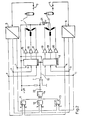
- Fig. 2 shows a block diagram for the synchronous drive of two identical, electronically commutated motors.
- Motors 1 and 2 are three-strand. Both motors are equipped with sensors 3, 4 for the detection of the phase position of the rotors, which work as optocouplers and evaluate a bar code which is attached to the circumference of the rotor.
- the output signal from optocoupler 3 is fed to a converter 5 and the signal from optocoupler 4 to a converter 6.
- the bar code within the converter e.g. B. with the help of a microprocessor, the assignment of the angular position of the rotors can be recognized.
- the converters have three outputs corresponding to the number of strands of the motors, each of which outputs a logic 1 signal at the same time when the rotor has reached its desired position according to FIG. 1, namely the comparison of the north and south poles.
- Switch 7 is fixed in the switch position shown for phase-synchronous starting and also for phase-synchronous control after starting. This ensures that the control units 8 and 9 at the same time only effect a further switching of the motor commutation via the common control line 10 when a corresponding takeover pulse appears on this line. This pulse is triggered by the output state of an OR circuit 14 in conjunction with the charge state of capacitor 22.
- the OR circuit 14 is activated by a combination of three EX-OR circuits 11, 12, 13, the outputs of which connect to the input of the OR Circuit 14 are connected, driven.
- Each first input of the Ex-OR circuits a, b, c is connected to the respective output of converter 5 and every second input of the Ex-OR circuits A, B, C is connected to the corresponding output of converter 6. bound.
- This arrangement ensures that the control units 8 and 9 work in quasi parallel operation and cause a synchronous output of the next commutation step.
- the inputs of the control units 8 and 9 are connected to the corresponding output lines of the converters 5 and 6. They are provided with an internal memory, assigned to each line, since a step forward in synchronous operation can only take place when the slower motor has reached its desired position. The control signals of the faster motor must therefore be maintained until the slower motor triggers the takeover for the next commutation step at the output of the OR circuit 14.
- control units 8 and 9 are followed by amplifiers 15 to 20 for each engine line, which are designed for the power adjustment for controlling the individual lines.
- Switch 7 is connected to ground for a deliberate asynchronous control of the motors.
- the control units 8 and 9 are switched from the positively synchronized quasi-parallel operation to individual operation.
- the commutation control is carried out separately for each motor, so that e.g. also desired speed differences can be set by means of controller 21.
Landscapes
- Engineering & Computer Science (AREA)
- Power Engineering (AREA)
- Control Of Motors That Do Not Use Commutators (AREA)
- Control Of Multiple Motors (AREA)
- Control Of Eletrric Generators (AREA)
- Electrical Discharge Machining, Electrochemical Machining, And Combined Machining (AREA)
- Control Of Ac Motors In General (AREA)
Priority Applications (1)
| Application Number | Priority Date | Filing Date | Title |
|---|---|---|---|
| AT87106747T ATE79705T1 (de) | 1986-05-17 | 1987-05-08 | Drehzahlsteuerung. |
Applications Claiming Priority (2)
| Application Number | Priority Date | Filing Date | Title |
|---|---|---|---|
| DE3616781 | 1986-05-17 | ||
| DE19863616781 DE3616781A1 (de) | 1986-05-17 | 1986-05-17 | Drehzahlsteuerung |
Publications (3)
| Publication Number | Publication Date |
|---|---|
| EP0246522A2 true EP0246522A2 (fr) | 1987-11-25 |
| EP0246522A3 EP0246522A3 (en) | 1988-10-26 |
| EP0246522B1 EP0246522B1 (fr) | 1992-08-19 |
Family
ID=6301122
Family Applications (1)
| Application Number | Title | Priority Date | Filing Date |
|---|---|---|---|
| EP87106747A Expired - Lifetime EP0246522B1 (fr) | 1986-05-17 | 1987-05-08 | Commande de vitesse |
Country Status (7)
| Country | Link |
|---|---|
| EP (1) | EP0246522B1 (fr) |
| JP (1) | JPS62277090A (fr) |
| KR (1) | KR910000100B1 (fr) |
| AT (1) | ATE79705T1 (fr) |
| DE (2) | DE3616781A1 (fr) |
| ES (1) | ES2033724T3 (fr) |
| GR (1) | GR3006264T3 (fr) |
Cited By (1)
| Publication number | Priority date | Publication date | Assignee | Title |
|---|---|---|---|---|
| FR2843248A1 (fr) * | 2002-07-30 | 2004-02-06 | Moving Magnet Tech Mmt | Procede de commande de fonctionnement synchronise d'au moins deux moteurs electriques polyphases |
Families Citing this family (1)
| Publication number | Priority date | Publication date | Assignee | Title |
|---|---|---|---|---|
| JP5772726B2 (ja) * | 2012-05-31 | 2015-09-02 | 株式会社デンソー | 空調装置用制御装置 |
Family Cites Families (3)
| Publication number | Priority date | Publication date | Assignee | Title |
|---|---|---|---|---|
| JPS5846885A (ja) * | 1981-09-08 | 1983-03-18 | Tipton Mfg Corp | 汎用電動機の回転軸の回転角位相同期制御方法及び装置 |
| DE3309370A1 (de) * | 1983-03-16 | 1984-09-20 | Zinser Textilmaschinen Gmbh, 7333 Ebersbach | Verfahren und antriebsvorrichtung zur einflussnahme auf das hochfahren und auslaufen von zwei asynchronmotoren |
| JP2526855B2 (ja) * | 1984-04-14 | 1996-08-21 | トヨタ自動車株式会社 | ブラシレスモ−タ制御装置 |
-
1986
- 1986-05-17 DE DE19863616781 patent/DE3616781A1/de not_active Withdrawn
-
1987
- 1987-05-08 AT AT87106747T patent/ATE79705T1/de not_active IP Right Cessation
- 1987-05-08 DE DE8787106747T patent/DE3781200D1/de not_active Expired - Fee Related
- 1987-05-08 ES ES198787106747T patent/ES2033724T3/es not_active Expired - Lifetime
- 1987-05-08 EP EP87106747A patent/EP0246522B1/fr not_active Expired - Lifetime
- 1987-05-16 KR KR1019870004840A patent/KR910000100B1/ko not_active Expired
- 1987-05-18 JP JP62119142A patent/JPS62277090A/ja active Pending
-
1992
- 1992-11-18 GR GR920402622T patent/GR3006264T3/el unknown
Cited By (2)
| Publication number | Priority date | Publication date | Assignee | Title |
|---|---|---|---|---|
| FR2843248A1 (fr) * | 2002-07-30 | 2004-02-06 | Moving Magnet Tech Mmt | Procede de commande de fonctionnement synchronise d'au moins deux moteurs electriques polyphases |
| WO2004017510A1 (fr) * | 2002-07-30 | 2004-02-26 | Moving Magnet Technologies 'm.M.T.' | Procede de commande de fonctionnement synchronise d'au moins deux moteurs electriques polyphases |
Also Published As
| Publication number | Publication date |
|---|---|
| JPS62277090A (ja) | 1987-12-01 |
| EP0246522B1 (fr) | 1992-08-19 |
| GR3006264T3 (fr) | 1993-06-21 |
| KR870011745A (ko) | 1987-12-26 |
| DE3616781A1 (de) | 1987-11-19 |
| EP0246522A3 (en) | 1988-10-26 |
| DE3781200D1 (de) | 1992-09-24 |
| ATE79705T1 (de) | 1992-09-15 |
| KR910000100B1 (ko) | 1991-01-19 |
| ES2033724T3 (es) | 1993-04-01 |
Similar Documents
| Publication | Publication Date | Title |
|---|---|---|
| DE2827340C2 (de) | Antriebseinrichtung mit wenigstens zwei Elektromotoren | |
| DE2837187C2 (fr) | ||
| DE69410476T2 (de) | Pulsbreitenmodulierter motorregler | |
| EP0485751B1 (fr) | Procédé pour la détermination du nombre de tours d'un moteur à courant continu sans balais | |
| DE69017152T2 (de) | Regelung eines bürstenlosen Motors mit mehreren Phasen und ohne Positionssensoren für den Rotor, unter Verwendung eines Systems der digitalen Filterung. | |
| DE10033561B4 (de) | Elektronisch kommutierter Motor mit Kommutierungssignal | |
| DE10023370A1 (de) | System zur elektronischen Kommutierung eines bürstenlosen Gleichstrommotors | |
| DE3140034A1 (de) | "elektromechanischer energieumwandler" | |
| DE3226548A1 (de) | Steuerung fuer buerstenlose gleichstrommotoren | |
| DE3528765C2 (fr) | ||
| DE112016000905T5 (de) | Motorsteuervorrichtung | |
| DE3819062C2 (fr) | ||
| EP0259764B1 (fr) | Circuit de commande pour la commutation électronique d'un moteur à courant continu | |
| DE1638104C2 (de) | System zur Umwandlung digitaler elektrischer Steuersignale in diskrete, abgestufte Winkelbewegungen in einem mehrphasigen elektrischen Schrittmotor | |
| DE3036908A1 (de) | Kollektorloser elektronikmotor | |
| EP0246522B1 (fr) | Commande de vitesse | |
| EP0195782B1 (fr) | Procede pour le demarrage d'un moteur a courant continu commute electroniquement | |
| DE3118991A1 (de) | "einrichtung zur frequenzmessung eines eine variable groesse darstellenden elektrischen stroms" | |
| EP0685927B1 (fr) | Méthode de freinage pour un moteur synchrone tournant inversement actionné par un réseau à cc | |
| DE1437154B2 (de) | Schaltungsanordnung zur Synchronisierung der Drehzahl eines Synchronmotors auf die Frequenz eines Bezugsoszillators | |
| DE4444907A1 (de) | Sensorsystem | |
| DE19524118C2 (de) | Verfahren und Vorrichtung zum drehgeschwindigkeitsabhängigen Ansteuern eines Mehrphasen-Schrittmotors | |
| EP1553690A1 (fr) | Méthode, système et moteur pour synchroniser la vitesse d'au moins deux moteurs | |
| DE1437154C (de) | Schaltungsanordnung zur Synchroni sierung der Drehzahl eines Synchronmotors auf die Frequenz eines Bezugsoszillators | |
| DE102009055126A1 (de) | Ansteuervorrichtung für eine elektrische Maschine und ein Motorsystem |
Legal Events
| Date | Code | Title | Description |
|---|---|---|---|
| PUAI | Public reference made under article 153(3) epc to a published international application that has entered the european phase |
Free format text: ORIGINAL CODE: 0009012 |
|
| AK | Designated contracting states |
Kind code of ref document: A2 Designated state(s): AT BE CH DE ES FR GB GR IT LI LU NL SE |
|
| PUAL | Search report despatched |
Free format text: ORIGINAL CODE: 0009013 |
|
| AK | Designated contracting states |
Kind code of ref document: A3 Designated state(s): AT BE CH DE ES FR GB GR IT LI LU NL SE |
|
| 17P | Request for examination filed |
Effective date: 19890413 |
|
| 17Q | First examination report despatched |
Effective date: 19920116 |
|
| GRAA | (expected) grant |
Free format text: ORIGINAL CODE: 0009210 |
|
| ITF | It: translation for a ep patent filed | ||
| AK | Designated contracting states |
Kind code of ref document: B1 Designated state(s): AT BE CH DE ES FR GB GR IT LI LU NL SE |
|
| REF | Corresponds to: |
Ref document number: 79705 Country of ref document: AT Date of ref document: 19920915 Kind code of ref document: T |
|
| GBT | Gb: translation of ep patent filed (gb section 77(6)(a)/1977) | ||
| REF | Corresponds to: |
Ref document number: 3781200 Country of ref document: DE Date of ref document: 19920924 |
|
| ET | Fr: translation filed | ||
| REG | Reference to a national code |
Ref country code: ES Ref legal event code: FG2A Ref document number: 2033724 Country of ref document: ES Kind code of ref document: T3 |
|
| REG | Reference to a national code |
Ref country code: GR Ref legal event code: FG4A Free format text: 3006264 |
|
| PG25 | Lapsed in a contracting state [announced via postgrant information from national office to epo] |
Ref country code: GB Effective date: 19930508 Ref country code: AT Effective date: 19930508 |
|
| PG25 | Lapsed in a contracting state [announced via postgrant information from national office to epo] |
Ref country code: SE Effective date: 19930509 |
|
| PG25 | Lapsed in a contracting state [announced via postgrant information from national office to epo] |
Ref country code: ES Free format text: LAPSE BECAUSE OF NON-PAYMENT OF DUE FEES Effective date: 19930510 |
|
| PG25 | Lapsed in a contracting state [announced via postgrant information from national office to epo] |
Ref country code: LU Free format text: LAPSE BECAUSE OF NON-PAYMENT OF DUE FEES Effective date: 19930531 Ref country code: LI Effective date: 19930531 Ref country code: CH Effective date: 19930531 Ref country code: BE Effective date: 19930531 |
|
| PGFP | Annual fee paid to national office [announced via postgrant information from national office to epo] |
Ref country code: NL Payment date: 19930531 Year of fee payment: 7 Ref country code: GR Payment date: 19930531 Year of fee payment: 7 |
|
| PLBE | No opposition filed within time limit |
Free format text: ORIGINAL CODE: 0009261 |
|
| STAA | Information on the status of an ep patent application or granted ep patent |
Free format text: STATUS: NO OPPOSITION FILED WITHIN TIME LIMIT |
|
| 26N | No opposition filed | ||
| BERE | Be: lapsed |
Owner name: DEUTSCHE THOMSON-BRANDT G.M.B.H. Effective date: 19930531 |
|
| GBPC | Gb: european patent ceased through non-payment of renewal fee |
Effective date: 19930508 |
|
| PG25 | Lapsed in a contracting state [announced via postgrant information from national office to epo] |
Ref country code: FR Effective date: 19940131 |
|
| REG | Reference to a national code |
Ref country code: CH Ref legal event code: PL |
|
| PG25 | Lapsed in a contracting state [announced via postgrant information from national office to epo] |
Ref country code: DE Effective date: 19940201 |
|
| REG | Reference to a national code |
Ref country code: FR Ref legal event code: ST |
|
| PG25 | Lapsed in a contracting state [announced via postgrant information from national office to epo] |
Ref country code: GR Free format text: THE PATENT HAS BEEN ANNULLED BY A DECISION OF A NATIONAL AUTHORITY Effective date: 19941130 |
|
| PG25 | Lapsed in a contracting state [announced via postgrant information from national office to epo] |
Ref country code: NL Effective date: 19941201 |
|
| NLV4 | Nl: lapsed or anulled due to non-payment of the annual fee | ||
| EUG | Se: european patent has lapsed |
Ref document number: 87106747.6 Effective date: 19931210 |
|
| REG | Reference to a national code |
Ref country code: GR Ref legal event code: MM2A Free format text: 3006264 |
|
| REG | Reference to a national code |
Ref country code: ES Ref legal event code: FD2A Effective date: 19990301 |
|
| PG25 | Lapsed in a contracting state [announced via postgrant information from national office to epo] |
Ref country code: IT Free format text: LAPSE BECAUSE OF NON-PAYMENT OF DUE FEES;WARNING: LAPSES OF ITALIAN PATENTS WITH EFFECTIVE DATE BEFORE 2007 MAY HAVE OCCURRED AT ANY TIME BEFORE 2007. THE CORRECT EFFECTIVE DATE MAY BE DIFFERENT FROM THE ONE RECORDED. Effective date: 20050508 |