EP0246429B2 - Sonde zur Messung des Sauerstoff-Partialdruckes in einer Gasatmosphäre bezogen auf eine Referenzatmosphäre - Google Patents
Sonde zur Messung des Sauerstoff-Partialdruckes in einer Gasatmosphäre bezogen auf eine Referenzatmosphäre Download PDFInfo
- Publication number
- EP0246429B2 EP0246429B2 EP87104848A EP87104848A EP0246429B2 EP 0246429 B2 EP0246429 B2 EP 0246429B2 EP 87104848 A EP87104848 A EP 87104848A EP 87104848 A EP87104848 A EP 87104848A EP 0246429 B2 EP0246429 B2 EP 0246429B2
- Authority
- EP
- European Patent Office
- Prior art keywords
- reaction member
- probe
- measuring
- fact
- atmosphere
- Prior art date
- Legal status (The legal status is an assumption and is not a legal conclusion. Google has not performed a legal analysis and makes no representation as to the accuracy of the status listed.)
- Expired - Lifetime
Links
- 239000000523 sample Substances 0.000 title claims abstract description 27
- QVGXLLKOCUKJST-UHFFFAOYSA-N atomic oxygen Chemical compound [O] QVGXLLKOCUKJST-UHFFFAOYSA-N 0.000 title claims description 8
- 229910052760 oxygen Inorganic materials 0.000 title claims description 8
- 239000001301 oxygen Substances 0.000 title claims description 8
- 238000007789 sealing Methods 0.000 claims abstract description 8
- 239000007784 solid electrolyte Substances 0.000 claims abstract description 3
- 238000006243 chemical reaction Methods 0.000 claims description 36
- 239000007789 gas Substances 0.000 claims description 17
- 229910052751 metal Inorganic materials 0.000 claims description 7
- 239000002184 metal Substances 0.000 claims description 7
- AXZKOIWUVFPNLO-UHFFFAOYSA-N magnesium;oxygen(2-) Chemical compound [O-2].[Mg+2] AXZKOIWUVFPNLO-UHFFFAOYSA-N 0.000 claims description 3
- 229910000831 Steel Inorganic materials 0.000 claims description 2
- 229910010293 ceramic material Inorganic materials 0.000 claims description 2
- 239000000395 magnesium oxide Substances 0.000 claims description 2
- CPLXHLVBOLITMK-UHFFFAOYSA-N magnesium oxide Inorganic materials [Mg]=O CPLXHLVBOLITMK-UHFFFAOYSA-N 0.000 claims description 2
- 239000010959 steel Substances 0.000 claims description 2
- 239000011324 bead Substances 0.000 description 8
- BASFCYQUMIYNBI-UHFFFAOYSA-N platinum Chemical compound [Pt] BASFCYQUMIYNBI-UHFFFAOYSA-N 0.000 description 7
- 238000005259 measurement Methods 0.000 description 5
- 239000012528 membrane Substances 0.000 description 5
- 238000010438 heat treatment Methods 0.000 description 4
- 239000002245 particle Substances 0.000 description 4
- 239000000853 adhesive Substances 0.000 description 3
- 230000001070 adhesive effect Effects 0.000 description 3
- 239000003792 electrolyte Substances 0.000 description 3
- 238000012423 maintenance Methods 0.000 description 3
- 229910052697 platinum Inorganic materials 0.000 description 3
- CURLTUGMZLYLDI-UHFFFAOYSA-N Carbon dioxide Chemical compound O=C=O CURLTUGMZLYLDI-UHFFFAOYSA-N 0.000 description 2
- QCWXUUIWCKQGHC-UHFFFAOYSA-N Zirconium Chemical compound [Zr] QCWXUUIWCKQGHC-UHFFFAOYSA-N 0.000 description 2
- PNEYBMLMFCGWSK-UHFFFAOYSA-N aluminium oxide Inorganic materials [O-2].[O-2].[O-2].[Al+3].[Al+3] PNEYBMLMFCGWSK-UHFFFAOYSA-N 0.000 description 2
- 239000000919 ceramic Substances 0.000 description 2
- 238000002485 combustion reaction Methods 0.000 description 2
- 238000004519 manufacturing process Methods 0.000 description 2
- 238000011282 treatment Methods 0.000 description 2
- 229910052726 zirconium Inorganic materials 0.000 description 2
- OKTJSMMVPCPJKN-UHFFFAOYSA-N Carbon Chemical compound [C] OKTJSMMVPCPJKN-UHFFFAOYSA-N 0.000 description 1
- UGFAIRIUMAVXCW-UHFFFAOYSA-N Carbon monoxide Chemical compound [O+]#[C-] UGFAIRIUMAVXCW-UHFFFAOYSA-N 0.000 description 1
- 230000015572 biosynthetic process Effects 0.000 description 1
- 229910052799 carbon Inorganic materials 0.000 description 1
- 239000006229 carbon black Substances 0.000 description 1
- 229910002092 carbon dioxide Inorganic materials 0.000 description 1
- 239000001569 carbon dioxide Substances 0.000 description 1
- 229910002091 carbon monoxide Inorganic materials 0.000 description 1
- 239000000356 contaminant Substances 0.000 description 1
- 238000010292 electrical insulation Methods 0.000 description 1
- 238000002474 experimental method Methods 0.000 description 1
- 238000004880 explosion Methods 0.000 description 1
- 239000000295 fuel oil Substances 0.000 description 1
- 239000012535 impurity Substances 0.000 description 1
- 238000002955 isolation Methods 0.000 description 1
- 239000007788 liquid Substances 0.000 description 1
- 150000002739 metals Chemical class 0.000 description 1
- 239000000203 mixture Substances 0.000 description 1
- 238000012544 monitoring process Methods 0.000 description 1
- 239000003921 oil Substances 0.000 description 1
- SIWVEOZUMHYXCS-UHFFFAOYSA-N oxo(oxoyttriooxy)yttrium Chemical compound O=[Y]O[Y]=O SIWVEOZUMHYXCS-UHFFFAOYSA-N 0.000 description 1
- RVTZCBVAJQQJTK-UHFFFAOYSA-N oxygen(2-);zirconium(4+) Chemical compound [O-2].[O-2].[Zr+4] RVTZCBVAJQQJTK-UHFFFAOYSA-N 0.000 description 1
- 230000000149 penetrating effect Effects 0.000 description 1
- 150000003839 salts Chemical class 0.000 description 1
- 230000035939 shock Effects 0.000 description 1
- 238000005476 soldering Methods 0.000 description 1
- 230000007704 transition Effects 0.000 description 1
- 229910001928 zirconium oxide Inorganic materials 0.000 description 1
Images
Classifications
-
- G—PHYSICS
- G01—MEASURING; TESTING
- G01N—INVESTIGATING OR ANALYSING MATERIALS BY DETERMINING THEIR CHEMICAL OR PHYSICAL PROPERTIES
- G01N27/00—Investigating or analysing materials by the use of electric, electrochemical, or magnetic means
- G01N27/26—Investigating or analysing materials by the use of electric, electrochemical, or magnetic means by investigating electrochemical variables; by using electrolysis or electrophoresis
- G01N27/403—Cells and electrode assemblies
- G01N27/406—Cells and probes with solid electrolytes
- G01N27/4067—Means for heating or controlling the temperature of the solid electrolyte
Definitions
- the present invention relates to a measuring probe according to the preamble of patent claim 1.
- the reaction element of which is composed of a zirconium particle and the tightness between the two atmospheres is ensured either by a removable seal or by soldering the particle onto its carrier.
- the particle is expensive due to its manufacture and maintenance. The particle must be replaced at the end of its life, and so must its carrier if the two are soldered together, or its seal, if one is used.
- reaction element usually consists of sintered zirconium, which has been stabilized with yttrium oxide.
- Reaction elements of the type mentioned can also be used to monitor the combustion in boilers with heavy oil or gas or in explosion engines to determine the ratio of carbon monoxide to carbon dioxide in the combustion or exhaust gases.
- the probes are inserted directly into the treatment area and exposed to very different temperatures as well as thermal and / or mechanical shocks.
- the temperatures can vary from the ambient temperature up to average temperatures of 800 to 1250 ° C.
- the ceramic systems are the most resistant at such temperatures. If platinum is used for the electrical contact of the outer electrode or for the seal, the service life is limited due to the aggressiveness of the carbon black against platinum. As a result, the aim is to omit the gasket and the platinum part in the outer electrode.
- Patent application EP-A 0 117 230 discloses a generic probe in which the reaction element is designed to be rotationally symmetrical as a disk and is arranged in a frustoconical or cylindrical region of the tubular support.
- a platinum sealing ring is arranged between the reaction element and a flat shoulder formed in the enlarged area of the tubular support.
- the formation of the expanded area of the tubular support and the need to arrange a sealing ring leads to a relatively large manufacturing effort;
- the need to arrange a sealing ring also means that when a reaction element is replaced, the sealing ring must also be replaced or at least checked to see whether it still meets the requirements with regard to its sealing properties.
- French patent application FR-A 2 390 727 describes a measuring cell by means of which the oxygen content in a gas mixture can be determined.
- a frustoconical plate is in direct contact with a metallic shell and a sleeve made of alumina.
- This measuring cell should hardly work satisfactorily because the contact surfaces between the plate on the one hand and the metal shell and the alumina sleeve on the other hand cannot guarantee the required tightness.
- the different coefficients of expansion of the above-mentioned parts must lead to leaks which render the cell in question unusable. With a metal support you also cause a short circuit.
- the American patent 4,339,318 also relates to a device for analyzing an oxygen-containing gas.
- the cylindrically shaped metal plate is arranged in a shoulder, which forms the transition between two cylindrical bores of different diameters.
- the required tightness can obviously only be guaranteed by using an adhesive; moreover, the tile is not interchangeable.
- the American patent specification 3,616,407 shows a device for determining the oxygen content for metals in a liquid state.
- a spherical electrolyte is used, which is arranged in a spherical seat in the front part of a tube.
- the spherical electrolyte which obviously has to be assembled in the deformable state before the ceramic material is fired, is not interchangeable and its seat has gas-permeable points, which are caused by the different thermal expansion coefficients of the tube and the electrolyte cell.
- the device described is not suitable for measuring the oxygen partial pressure in a gas atmosphere.
- a generic probe of this type which has become known through prior use, the structure of which results from the published DE-A-35 03155, shows a reaction element which is designed in the form of a sleeve with a disc-shaped head and provided with an eccentric bore, in the annular shoulder of which the front section of an extension tube engages.
- the reaction element and the front section of the extension tube are pressed against one another by an elastic force.
- Figures 1 and 2 show a probe for the continuous measurement of the oxygen partial pressure of a gas atmosphere in relation to air as a reference gas.
- reaction element in the form of a bead made of a solid electrolyte, which consists of sintered and stabilized zirconium oxide.
- This ball rests on a tight seat 2 of a ceramic carrier 3.
- a sleeve 4 made of heat-resistant steel serves as an outer electrode and has a counter seat 5, which forms the end, while the other end of the carrier 3 connects to a disc 6, which is connected is supported on a spring 8 via an airtight membrane 7.
- This arrangement enables the bead 1 to be fixed with the required pressure, which is exerted against the same on the one hand and against the seat 2 and against the counter seat 5.
- a pin 9 which is arranged in the interior of the carrier 3 and forms an inner electrode, carries a spring plate 10 for a spring 11, the pin 9 pressing a contact shoe 12 against the bead 1.
- the totality of beads 1, seat 2, counter seat 5 and contact shoe 12 form the measuring head.
- the end of the sleeve 4 has openings 13 which serve for the passage of the measuring gas 14. It can be seen in FIG. 1 that the contact surface between the bead 1 and the gas-tight seat 2 of the carrier 3 has no seal.
- the inner sift 9 has a chamber 15 in which a thermocouple 16 is arranged, which is connected to two terminals of a connection 17 via two wires 18, 19, the wires 18, 19 den Cross pin 9 lengthways in two corresponding channels 20,21.
- the inner pin 9 also has two further longitudinal channels 22 and 23. In the channel 22 is a wire 24 which connects the contact shoe 12 to the connector 17.
- the channel 23 allows access of reference air, which flows along the lower surface of the bead 1 and escapes between the pin 9 below and the carrier 3 through an opening 25 of the disk 6 and the opening 26 of a housing described below.
- the end of the sleeve 4, which contains the head of the probe, is used, for example, in the measuring area of a furnace in which the atmosphere is to be measured, the sleeve penetrating a wall 27 in this measuring area.
- the probe also comprises a gas-tight housing 28, which is constructed on the one hand from a casing 29 with a neck 30, in which the sleeve 4 is screwed, and on the other hand from a removable cover 29 '.
- the gas-tight membrane 7 already mentioned is clamped between two rings 31 and 32, while a second gas-tight membrane 34 is clamped between the ring 32 and a shoulder 35.
- the cover 29 ' has a reference air inlet 36, which opens into a flow meter 37 arranged in the ring 31, which in turn comprises a float 38 and a micrometer 39.
- the reference air penetrates into the space below the membrane 7 through an opening 40 of the flow meter in order to pass through the aforementioned access into the space delimited by the two membranes 7 and 34 as well as through the opening 26 provided in the ring 32 and the casing 29.
- the latter has an opening 41, which is connected to an additional air inlet, which is denoted schematically by the reference number 42 and is controlled by a solenoid valve 43, in order to clean and burn sporadically any impurities in the measuring head.
- the casing 29 also has an outlet opening 44 which opens into an outflow line 45 with a control valve 146, so that samples can be taken from the gas to be examined for analysis purposes.
- connection 17 is connected directly to an electronic monitoring or control device, not shown. It has four contact terminals 47, 48, 49, 50, of which the first two to the wires 18, 19 of the thermocouple, the contact terminal 49 to the negative polarity wire 24 of the inner electrode 9 and the positive polarized contact terminal 50 to the housing 28 is connected.
- the embodiment variant according to FIG. 3, in which corresponding parts are identified by the same reference numerals as above, comprises a metallic tube 51 as the inner electrode, which is filled with magnesium oxide 52 and is elastically supported with its upper, rounded end against the bead 1.
- the tube 51 contains a thermocouple 53 which is connected via two wires to the contact terminals 47, 48 of a connection not shown in FIG. 3, but which is identical to that provided with the reference number 17 in FIG. 1.
- the thermocouple also has the same function.
- the metal tube 51 is connected to the contact clamp 49.
- the tube 51 is arranged concentrically in a tube 54, so that between the two there is a passage 55 for the reference air 56 directed against the bead.
- FIG. 4 shows an embodiment variant of the counter seat 5 of the sleeve 4, which improves the electrical contact between the latter and the reaction element 1.
- the two ends of the tubular support 3 are provided with spherical seats 2 (FIG. 1), so that the tubular support can be turned over in the event of damage or wear and in this way has a considerable service life.
Landscapes
- Chemical & Material Sciences (AREA)
- Life Sciences & Earth Sciences (AREA)
- Health & Medical Sciences (AREA)
- Biochemistry (AREA)
- General Physics & Mathematics (AREA)
- Electrochemistry (AREA)
- Physics & Mathematics (AREA)
- Analytical Chemistry (AREA)
- Molecular Biology (AREA)
- General Health & Medical Sciences (AREA)
- Chemical Kinetics & Catalysis (AREA)
- Immunology (AREA)
- Pathology (AREA)
- Measuring Oxygen Concentration In Cells (AREA)
- Sampling And Sample Adjustment (AREA)
- Investigating Or Analyzing Materials By The Use Of Fluid Adsorption Or Reactions (AREA)
- Measuring Arrangements Characterized By The Use Of Fluids (AREA)
Description
- Die vorliegende Erfindung betrifft eine Messonde gemäss Oberbegriff des Patentanspruches 1.
- Es sind verschiedene Sonden bekannt, deren Reaktionselement aus einem Zirkoniumteilchen aufgebaut ist und deren Dichtigkeit zwischen den beiden Atmosphären entweder durch eine abnehmbare Dichtung oder durch Festlöten des Teilchens auf seinen Träger gewährleistet ist. Doch ist das Teilchen infolge Herstellung und Unterhalt kostspielig. Das Teilchen muss nach Ablauf seiner Lebensdauer ersetzt werden und ebenso sein Träger, falls die beiden miteinanderverlötetsind, oderseine Dichtung, sofern eine solche verwendet wird.
- Derartige Sonden werden zur Ueberwachung von Wärmebehandlungs-Oefen eingesetzt, in welchen gesteuerte Härte- und Wärmebehandlungen durchgeführt werden. Das Reaktionselement besteht in der Regel aus gesintertem Zirkonium, das mit Yttriumoxid stabilisiert wurde. Reaktionselemente der genannten Art können auch zur Ueberwachung der Verbrennung in Heizkesseln mit Schweröl oder Gas oder in Explosionsmotoren verwendet werden, um das Verhältnis von Kohlenmonoxid zu Kohlendioxid in den Verbrennungs- bzw. Abgasen zu bestimmen.
- Bei Wärmebehandlungen werden die Sonden direkt in den Behandlungsbereich eingeführt und sehr unterschiedlichen Temperaturen sowie thermischen und/odermechanischen Schocks ausgesetzt. Hierbei können die Temperaturen von der Umgebungstemperatur bis zu mittleren Temperaturen von 800 bis 1250 °C variieren. Bei solchen Temperaturen sind die keramischen Systeme am widerstandsfähigsten. Sofern man für den elektrischen Kontakt der äusseren Elektrode oder für die Dichtung Platin verwendet, ist die Lebensdauer infolge derAgressivität des Russes gegenüber Platin begrenzt. Infolgedessen wird angestrebt, die Dichtung und das Platinteil in derAussenelektrode wegzulassen.
- Die wichtigsten Voraussetzungen für eine einwandfreie Funktion einer Messonde können wie folgt zusammengefasst werden:
- 1. Gasdichtigkeit zwischen den beiden Zonen des Reaktionselementes, damit die Messatmosphäre mit der Referenzatmosphäre nicht vermischt wird.
Es ist möglich, dass während des Betriebes die Behandlungsumgebung durch Oeldämpfe, Salz oder durch Rückstände an den zu behandelnden Teilen verschmutzt ist, selbst wenn letztere gewaschen werden. Infolgedessen können die Reaktionselemente mit Dampf beschlagen werden, woraus eine Messabweichung resultiert. In solchen Fällen ist es erforderlich, die Verunreinigungen zu verbrennen oder Reaktionselement und Dichtung schleunigst auszuwechseln, was eine kostspielige Massnahme bedeutet. - 2. Die Verwirklichung einer Gasdichtigkeit, ohne Dichtungen oder Klebestoffe zu verwenden.
- 3. Eine elektrische Isolation zwischen den beiden Zonen des Reaktionselementes (Mess- und Referenzgas), um eine elektrische Potentialdifferenz erreichen zu können und einen Kurzschluss durch einen Metallträger zu vermeiden.
- 4. Leichte Auswechselbarkeit des Reaktionselementes.
- Die bisher bekannten Sonden sind weit davon entfernt, diese Voraussetzungen zu erfüllen.
- Durch die Patentanmeldung EP-A 0 117 230 ist eine gattungsgemässe Sonde bekannt, bei der das Reaktionselement rotationssymmetrisch als Scheibe ausgebildet und in einem kegelstumpfförmig bzw. zlindrisch erweiterten Bereich des rohrförmigen Trägers angeordnet ist. Um die erforderliche Gasdichtigkeit zwischen den beiden Zonen des Reaktionselementes sicherzustellen, ist zwischen dem Reaktionselement und einer in dem erweiterten Bereich des rohrförmigen Trägers ausgebildeten ebenen Schulter ein Dichtring aus Platin angeordnet. Der Ausbildung des erweiterten Bereichs des rohrförmigen Trägers sowie die Notwendigkeit einen Dichtring anzuordnen führt zu einem relativ grossen Herstellungsaufwand; die Notwendigkeit einen Dichtring anzuordnen hat ferner zur Folge, dass bei einem Auswechseln eines Reaktionselementes auch der Dichtring ausgewechselt oder zumindest dahingehend überprüft werden muss, ob er hinsichtlich seiner Dichteigenschaften den Erfordernissen noch genügt.
- Die französische Patentanmeldung FR-A 2 390 727 beschreibt eine Messzelle, mittels welcher der Sauerstoffgehalt in einem Gasgemisch bestimmt werden kann. Ein kegelstumpfförmiges Plättchen ist in direktem Kontakt mit einer metallischen Hülle und einer Hülse aus Tonerde. Diese Messzelle dürfte kaum in befriedigender Weise arbeiten, weil die Kontaktflächen zwischen dem Plättchen einerseits und der Metallhülle sowie der Tonerdenhülse andererseits die erforderliche Dichtigkeit nicht gewährleisten können. Tatsächlich müssen die unterschiedlichen Ausdehnungskoeffizienten der obengenannten Teile zwingend zu undichten Stellen führen, welche die besagte Zelle unbrauchbar machen. Mit einem Metallträger verursacht man überdies einen Kurzschluss.
- Die amerikanische Patentschrift 4.339.318 betrifft ebenfalls eine Vorrichtung zur Analyse eines sauerstoffhaltigen Gases. Das zylindrisch geformte Metallplättchen ist in einer Schulter angeordnet, welche den Uebergang zwischen zwei zylindrischen Bohrungen von unterschiedlichem Durchmesser bildet. Die geforderte Dichtigkeit kann offensichtlich nur unter Verwendung eines Klebstoffes gewährleistet werden; darüber hinaus ist das Plättchen nicht auswechselbar.
- Die amerikanische Patentschrift 3.616.407 zeigt ein Gerät zur Bestimmung des Sauerstoffgehaltes bei Metallen in flüssigem Zustand. Man verwendet einen sphärischen Elektrolyten, der in einem sphärischen Sitz im Vorderteil eines Rohres angeordnet ist. Der sphärische Elektrolyt, der offensichtlich im verformbaren Zustand vor dem Brennen des KeramikMaterials montiert werden muss, ist nicht auswechselbar und sein Sitz weist gasdurchlässige Stellen auf, welche infolge der unterschiedlichen Wärmeausdehnungskoeffizienten von Rohr und Elektrolyt-Zelle hervorgerufen werden. Darüber hinaus eignet sich die beschriebene Vorrichtung nicht zur Messung des Sauerstoffpartialdruckes in einer Gasatmosphäre.
- Eine durch Vorbenutzung bekanntgewordene, gattungsgemäße Sonde dieser Art, deren Aufbau sich aus der nach veröffentlichten DE-A-35 03155 ergibt, zeigt ein Reaktionselement, das in Form einer mit exzentrischer Bohrung versehenen Hülse mit scheibenförmigem Kopf ausgebildet ist, in deren Ringschulter der vordere Abschnitt eines Verlängerungsrohres eingreift. Das Reaktionselement und der vordere Abschnitt des Verlängerungsrohres werden durch eine elastische kraft abdichtend gegeneinander gepreßt.
- Es ist Aufgabe der Erfindung, die Auswechselbarkeit der Reaktionselemente zu erleichtern, zugleich eine gute Dichtigkeit zu gewährleisten, ohne dass eine Dichtung oder ein Klebestoff verwendet werden muss.
- Die Lösung dieser Aufgabe erfolgt gemäss kennzeichnendem Teil des unabhängigen Patentanspruches.
- Die Zeichnung zeigt ein Ausführungsbeispiel der erfindungsgemässen Sonde sowie verschiedene Varianten. Es zeigen:
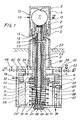
- Fig. 1 eine Ausführungsform der Sonde im Längsschnitt
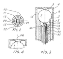
- Fig. 2 einen Schnitt 11-11 gemäss Fig. 1
- Fig. 3,4 je eine Ausführungsvariante eines Messkopfes.
- Die Figuren 1 und 2 zeigen eine Sonde für die kontinuierliche Messung des Sauerstoffpartialdruckes einer Gasatmosphäre in Bezug auf Luft als Referenzgas.
- Sie umfasst ein Reaktionselement in Form eines Kügelchens aus einem festen Elektrolyten, welcher aus gesintertem und stabilisiertem Zirkoniumoxid besteht. Dieses Kügelchen ruht auf einem dichten Sitz 2 eines keramischen Trägers 3. Eine Hülse 4 aus hitzebeständigem Stahl dient als äussere Elektrode und weist einen Gegensitz 5 auf, welcher den Abschluss bildet, während das andere Ende des Trägers 3 an eine Scheibe 6 anschliesst, die sich über eine luftdichte Membran 7 auf eine Feder 8 abstützt. Diese Anordnung ermöglicht die Fixierung des Kügelchens 1 mit dem erforderlichen Druck, welcher gegen selbiges einerseits und den Sitz 2 sowie gegen den Gegensitz 5 ausgeübt wird. Ein Stift 9, der im Inneren des Trägers 3 angeordnet ist und eine innere Elektrode bildet, trägt einen Federteller 10 für eine Feder 11, wobei der Stift 9 einen Kontaktschuh 12 gegen das Kügelchen 1 presst. Die Gesamtheit von Kügelchen 1, Sitz 2, Gegensitz 5 und Kontaktschuh 12 bilden den Messkopf.
- Das Ende der Hülse 4 weist Oeffnungen 13 auf, welche dem Durchtritt des Messgases 14 dienen. Man sieht in Figur 1, dass die Kontaktfläche zwischen dem Kügelchen 1 und dem gasdichten Sitz 2 des Trägers 3 keinerlei Dichtung aufweist. Wie man in Figur 2 besonders deutlich sehen kann, besitzt der innere Sift 9 eine Kammer 15, in welcher ein Thermoelement 16 angeordnet ist, das über zwei Drähte 18,19 mit zwei Klemmen eines Anschlusses 17 verbunden ist, wobei die Drähte 18,19 den Stift 9 in zwei entsprechenden Kanälen 20,21 in Längsrichtung durchqueren. Der innere Stift 9 beitzt ausserdem zwei weitere Längskanäle 22 und 23. Im Kanal 22 ist ein Draht 24, der den Kontaktschuh 12 mit dem Anschluss 17 verbindet. Der Kanal 23 erlaubt den Zutritt von Referenzluft, welche an der Unterfläche des Kügelchens 1 entlangströmt und zwischen dem Stift 9 unten und dem Träger 3 durch eine Oeffnung 25 der Scheibe 6 und die Oeffnung 26 eines weiter unten beschriebenen Gehäuses entweicht. Das Ende der Hülse 4, das den Kopf der Sonde enthält, wird beispielsweise im Messbereich eines Ofens eingesetzt, bei dem man die Atmosphäre messen will, wobei die Hülse in diesem Messbereich eine Wandung 27 durchdringt.
- Die Sonde umfasst ausserdem ein gasdichtes Gehäuse 28, das einerseits aus einer Hülle 29 mit einem Hals 30, in welcher die Hülse 4 festgeschraubt ist, und andererseits aus einem abnehmbaren Deckel 29' aufgebaut ist. Die schon erwähnte gasdichte Membran 7 ist zwischen zwei Ringen 31 und 32 festgeklemmt, während eine zweite gasdichte Membran 34 zwischen den Ring 32 und eine Schulter 35 festgeklemmt ist. Der Deckel 29' besitzt neben dem schon erwähnten Anschluss 17 einen Referenzlufteintritt 36, welcher in einem im Ring 31 angeordneten Durchflussmesser 37 mündet, der seinerseits einen Schwimmer 38 sowie eine Messchraube 39 umfasst.
- Die Referenzluft dringt in den unterhalb der Membran 7 befindlichen Raum durch eine Oeffnung 40 des Durchflussmessers, um durch den genannten Zugang in den durch die beiden Membranen 7 und 34 sowie durch die im Ring 32 vorgesehene Oeffnung 26 und die Hülle 29 begrenzten Raum zu gelangen. Letztere besitzt eine Oeffnung 41, welche mit einem zusätzlichen Lufteintritt verbunden ist, welcher schematisch mit der Hinweisziffer 42 bezeichnet ist und durch ein Magnetventil 43 gesteuert wird, um sporadisch allfällige Verunreinigungen im Messkopf zu reinigen und zu verbrennen. Die Hülle 29 weist ebenfalls eine Austrittsöffnung 44 auf, welche in eine Abströmleitung 45 mit einem Steuerventil 146 mündet, so dass hieraus dem zu untersuchenden Gas Proben fürAnalysezwecke entnommen werden können.
- Der Anschluss 17 wird direkt an ein nicht dargestelltes elektronisches Ueberwachungs- oder Steuergerät angeschlossen. Er weist vier Kontaktklemmen auf 47,48,49,50, von denen die beiden ersteren an die Drähte 18,19 des Thermoelementes, die Kontaktklemme 49 an den eine negative Polung aufweisenden Draht 24 der inneren Elektrode 9 und die positiv gepolte Kontaktklemme 50 am Gehäuse 28 angeschlossen ist.
- Die Sonde funktioniert wie folgt:
- Die vom Thermoelement 16 an den Kontaktklemmen 47,48 erzeugte Spannung entspricht in Millivolt der Temperatur des Messgases 14. Die zwischen den Kontaktklemmen 49 und 50, d.h. zwischen der inneren und äusseren Elektrode in direktem Kontakt mit dem Reaktionselement erzeugte Spannung, entspricht gemäss der Nernst'schen Gleichung in Millivolt der Sauerstoffkonzentration bezogen auf das Kohlenstoffpotential. Diese Spannung dient der Steuerung der für die Wärmebehandlungen erforderlichen Gasströme. Versuche haben gezeigt, dass die Messgenauigkeit mit Sonden der oben beschriebenen Art diejenige von herkömmlichen Sonden übertrifft.
- Für Unterhaltsarbeiten oderfürdas Auswechseln des Reaktionselementes 1 genügt es - dank dem in der Schulter 30 vorgesehenen, in der Figur jedoch nicht dargestellten Gewinde - die Hülse 4 vom Gehäuse 28 abzuschrauben und das Reaktionselement 1 vom Träger 3 zu entfernen, um den gesamten Messkopf freizugeben. Zugang und Unterhalt sind daher vereinfacht.
- Die Ausführungsvariante gemäss Figur 3, in der entsprechende Teile mit denselben Hinweisziffern wie oben bezeichent sind, umfasst ein metallisches Rohr 51 als innere Elektrode, das mit Magnesiumoxid 52 gefüllt ist und mit seinem oberen, abgerundeten Ende gegen das Kügelchen 1 elastisch abgestützt wird. Das Rohr 51 enthält ein Themoelement 53, das über zwei Drähte mit den Kontaktklemmen 47,48 eines in dieser Figur 3 nicht dargestellten Anschlusses verbunden ist, der aber mit dem in Figur 1 mit der Hinweisziffer 17 versehenen identisch ist. Das Thermoelement hat ebenfalls die gleiche Funktion.
- Das Metallrohr 51 ist mit der Kontaktklemme 49 verbunden. Das Rohr 51 ist konzentrisch in einem Rohr 54 angeordnet, so dass zwischen den beiden ein Durchtritt 55 für die gegen das Kügelchen gerichtete Referenzluft 56 vorhanden ist.
- Figur 4 zeigt eine Ausführungsvariante des Gegensitzes 5 der Hülse 4, welche den elektrischen Kontakt zwischen letzterer und dem Reaktionselement 1 verbessert.
- Gemäss einer weiteren Variante sind die beiden Enden des röhrenförmigen Trägers 3 mit sphärischen Sitzen 2 (Fig. 1) versehen, so dass der rohrförmige Träger, im Beschädigungs- oder Abnützungsfalle umgewendet werden kann und auf diese Weise eine beachtliche Lebensdauer aufweist.
Claims (8)
dass das Reaktionselement (1) eine Kugel ist und derart in der rohrförmigen Hulse (4) angeordnet ist, daß eine großflächige Beaufschlagung mit der Gasatmosphäre ermöglicht wird und daß der gegenüber dem Reaktionselement (1) dichtend ausgebildete Sitz (2) des rohrförmigen Trägers (3) von einer konstanten elastischen Kraft (8) direkt gegen die Kugel (1) gepresst wird.
Priority Applications (1)
| Application Number | Priority Date | Filing Date | Title |
|---|---|---|---|
| AT87104848T ATE56092T1 (de) | 1986-04-17 | 1987-04-02 | Sonde zur messung des sauerstoff-partialdruckes in einer gasatmosphaere bezogen auf eine referenzatmosphaere. |
Applications Claiming Priority (2)
| Application Number | Priority Date | Filing Date | Title |
|---|---|---|---|
| CH154386 | 1986-04-17 | ||
| CH1543/86 | 1986-04-17 |
Publications (3)
| Publication Number | Publication Date |
|---|---|
| EP0246429A1 EP0246429A1 (de) | 1987-11-25 |
| EP0246429B1 EP0246429B1 (de) | 1990-08-29 |
| EP0246429B2 true EP0246429B2 (de) | 1994-08-03 |
Family
ID=4212874
Family Applications (1)
| Application Number | Title | Priority Date | Filing Date |
|---|---|---|---|
| EP87104848A Expired - Lifetime EP0246429B2 (de) | 1986-04-17 | 1987-04-02 | Sonde zur Messung des Sauerstoff-Partialdruckes in einer Gasatmosphäre bezogen auf eine Referenzatmosphäre |
Country Status (6)
| Country | Link |
|---|---|
| US (1) | US4808294A (de) |
| EP (1) | EP0246429B2 (de) |
| AT (1) | ATE56092T1 (de) |
| DE (1) | DE3764538D1 (de) |
| ES (1) | ES2017658B3 (de) |
| FR (1) | FR2597602B3 (de) |
Cited By (2)
| Publication number | Priority date | Publication date | Assignee | Title |
|---|---|---|---|---|
| CN107400772A (zh) * | 2017-08-30 | 2017-11-28 | 盛红梅 | 一种热处理炉气氛传感器的安装结构 |
| CN107400771A (zh) * | 2017-08-30 | 2017-11-28 | 盛红梅 | 一种气氛传感器的安装结构 |
Families Citing this family (7)
| Publication number | Priority date | Publication date | Assignee | Title |
|---|---|---|---|---|
| US5167785A (en) * | 1989-10-07 | 1992-12-01 | Mccready David F | Thin electrodes |
| US5137616A (en) * | 1991-04-04 | 1992-08-11 | Surface Combustion, Inc. | Gas analysis system for furnaces and the like |
| US5211820A (en) * | 1991-04-04 | 1993-05-18 | Surface Combustion, Inc. | Gas analysis system for furnaces and the like |
| FR2735866B1 (fr) * | 1995-06-22 | 1997-08-29 | Crevoiserat Jean Michel | Sonde pour mesurer la pression partielle d'oxygene dans les cheminees domestiques et industrielles |
| US5635044A (en) * | 1995-08-11 | 1997-06-03 | Lotze; Thomas H. | Electrode for zirconia oxygen sensors |
| RU2270438C2 (ru) * | 2003-10-20 | 2006-02-20 | Открытое акционерное общество "Ангарское опытно-конструкторское бюро автоматики" | Способ измерения парциального давления кислорода |
| US8997558B2 (en) * | 2011-03-29 | 2015-04-07 | General Electric Company | Combustor probe for gas turbine |
Family Cites Families (16)
| Publication number | Priority date | Publication date | Assignee | Title |
|---|---|---|---|---|
| GB1073099A (en) * | 1965-06-10 | 1967-06-21 | Kent Ltd G | Improvements in or relating to electro-chemical gas measuring system |
| DE1598559B1 (de) * | 1965-10-14 | 1971-07-29 | Hoesch Ag | Vorrichtung zur Bestimmung der Aktivitaet,insbesondere von Sauerstoff in metallischen Baedern |
| US3768259A (en) * | 1971-07-06 | 1973-10-30 | Universal Oil Prod Co | Control for an engine system |
| CA983114A (en) * | 1973-07-18 | 1976-02-03 | Her Majesty In Right Of Canada As Represented By The Minister Of Energy, Mines And Resources | Oxygen probe with self-contained source of oxygen gas |
| US3940327A (en) * | 1975-04-11 | 1976-02-24 | Universal Oil Products Company | Oxygen sensing device |
| US4101404A (en) * | 1976-06-28 | 1978-07-18 | Blumenthal Robert N | Hot gas measuring device |
| CA1112438A (en) * | 1976-12-07 | 1981-11-17 | Robert R. Hughan | Oxygen sensors |
| IT1089129B (it) * | 1976-12-15 | 1985-06-18 | Uop Inc | Cella elettrochimica avente un elettrolita solido a superficie accresciuta e procedimento per prepararla |
| JPS53119993U (de) * | 1977-03-02 | 1978-09-25 | ||
| US4123344A (en) * | 1977-04-15 | 1978-10-31 | Bendix Autolite Corporation | Two fire ceramic sealed oxygen sensing device and method of forming same |
| FR2390727A1 (fr) * | 1977-05-11 | 1978-12-08 | Renault | Cellule de mesure permettant de determiner la concentration en oxygene dans un melange gazeux |
| FR2423777A1 (fr) * | 1978-04-18 | 1979-11-16 | Uop Inc | Capteur d'oxygene, notamment pour dispositif industriel de controle du rapport air/combustible et procede de fabrication d'un tel capteur |
| US4229275A (en) * | 1979-07-09 | 1980-10-21 | Uop Inc. | Solid electrolyte oxygen sensor and method of making same |
| US4339318A (en) * | 1979-12-27 | 1982-07-13 | Fuji Electric Co., Ltd. | Oxygen gas analyzing device |
| CH645722A5 (fr) * | 1983-02-04 | 1984-10-15 | Teresa Crevoiserat | Sonde pour la mesure de la pression partielle de l'oxygene dans une atmosphere de gaz. |
| US4537661A (en) * | 1984-05-24 | 1985-08-27 | Westinghouse Electric Corp. | Technique for monitoring the oxidation/reduction potential characteristics of a steam environment |
-
1987
- 1987-04-02 AT AT87104848T patent/ATE56092T1/de not_active IP Right Cessation
- 1987-04-02 ES ES87104848T patent/ES2017658B3/es not_active Expired - Lifetime
- 1987-04-02 EP EP87104848A patent/EP0246429B2/de not_active Expired - Lifetime
- 1987-04-02 DE DE8787104848T patent/DE3764538D1/de not_active Expired - Lifetime
- 1987-04-10 US US07/036,756 patent/US4808294A/en not_active Expired - Fee Related
- 1987-04-16 FR FR8705441A patent/FR2597602B3/fr not_active Expired
Cited By (2)
| Publication number | Priority date | Publication date | Assignee | Title |
|---|---|---|---|---|
| CN107400772A (zh) * | 2017-08-30 | 2017-11-28 | 盛红梅 | 一种热处理炉气氛传感器的安装结构 |
| CN107400771A (zh) * | 2017-08-30 | 2017-11-28 | 盛红梅 | 一种气氛传感器的安装结构 |
Also Published As
| Publication number | Publication date |
|---|---|
| DE3764538D1 (de) | 1990-10-04 |
| FR2597602A3 (fr) | 1987-10-23 |
| EP0246429A1 (de) | 1987-11-25 |
| ATE56092T1 (de) | 1990-09-15 |
| ES2017658B3 (es) | 1991-03-01 |
| EP0246429B1 (de) | 1990-08-29 |
| FR2597602B3 (fr) | 1988-09-09 |
| US4808294A (en) | 1989-02-28 |
Similar Documents
| Publication | Publication Date | Title |
|---|---|---|
| EP0701692B1 (de) | Messfühleranordnung in einer gasleitung | |
| DE2452924C3 (de) | Elektrochemischer MeBfühler | |
| EP0701693B1 (de) | Gassensor | |
| EP0246429B2 (de) | Sonde zur Messung des Sauerstoff-Partialdruckes in einer Gasatmosphäre bezogen auf eine Referenzatmosphäre | |
| WO1994029710A9 (de) | Dichtung für ein sensorelement eines gassensors | |
| US3909202A (en) | Apparatus for analysis of liquids | |
| DE10253917A1 (de) | Gassensor | |
| DE3035608C2 (de) | ||
| DE3027863A1 (de) | Flammenionisationsdetektor | |
| DE2716187B2 (de) | Sonde zur Bestimmung von Veränderungen in der Zusammensetzung eines Gasgemisches | |
| DE2719138A1 (de) | Sensorvorrichtung zum messen der sauerstoffkonzentration in den auspuffgasen von verbrennungsmotoren | |
| DE2319859A1 (de) | Gasanalysensonde | |
| US4592825A (en) | Probe for measuring oxygen partial pressure in a gas atmosphere | |
| DE3118447C2 (de) | Sauerstoffmeßsonde, insbesondere zum Erfassen des Sauerstoffgehaltes einer kohlenstoffhaltigen Atmosphäre | |
| DE2350253C3 (de) | Elektrochemischer Meßfühler | |
| DE1598914B2 (de) | Flammenionisationsdetektor | |
| DE2350485A1 (de) | Elektrochemisches messgeraet zur kontinuierlichen bestimmung der sauerstoffaktivitaet in gasen, metall- oder salzschmelzen | |
| DE1798002C3 (de) | Meßsonde zur Bestimmung des Sauerstoffgehaltes in Gasen, Dämpfen und Flüssigkeiten, insbesondere in flüssigen Metallen | |
| DE3910148C2 (de) | ||
| DE102004050630B4 (de) | Lambdasonde zur Analyse von Abgasen | |
| DE3800807A1 (de) | Durch druckmittel steuerbares 2/2-wegeventil | |
| EP4462094B1 (de) | Temperaturfühler | |
| DE1949081A1 (de) | Staubfilter mit elektrischer Heizeinrichtung zur Einschaltung in die Messgasleitung eines Gasanalysatorgeraetes | |
| DE3503155C2 (de) | Sauerstoffmeßsonde | |
| DE3621652C1 (de) | Messonde zur Analyse eines Gases sowie Anwendung derselben |
Legal Events
| Date | Code | Title | Description |
|---|---|---|---|
| PUAI | Public reference made under article 153(3) epc to a published international application that has entered the european phase |
Free format text: ORIGINAL CODE: 0009012 |
|
| AK | Designated contracting states |
Kind code of ref document: A1 Designated state(s): AT BE CH DE ES FR GB GR IT LI LU NL SE |
|
| 17P | Request for examination filed |
Effective date: 19871223 |
|
| 17Q | First examination report despatched |
Effective date: 19890606 |
|
| RAP3 | Party data changed (applicant data changed or rights of an application transferred) |
Owner name: BEURET, JACQUES Owner name: BEURET, PIERRE |
|
| GRAA | (expected) grant |
Free format text: ORIGINAL CODE: 0009210 |
|
| AK | Designated contracting states |
Kind code of ref document: B1 Designated state(s): AT BE CH DE ES FR GB GR IT LI LU NL SE |
|
| PG25 | Lapsed in a contracting state [announced via postgrant information from national office to epo] |
Ref country code: SE Free format text: THE PATENT HAS BEEN ANNULLED BY A DECISION OF A NATIONAL AUTHORITY Effective date: 19900829 Ref country code: NL Effective date: 19900829 Ref country code: GR Free format text: LAPSE BECAUSE OF FAILURE TO SUBMIT A TRANSLATION OF THE DESCRIPTION OR TO PAY THE FEE WITHIN THE PRESCRIBED TIME-LIMIT Effective date: 19900829 |
|
| REF | Corresponds to: |
Ref document number: 56092 Country of ref document: AT Date of ref document: 19900915 Kind code of ref document: T |
|
| GBT | Gb: translation of ep patent filed (gb section 77(6)(a)/1977) | ||
| REF | Corresponds to: |
Ref document number: 3764538 Country of ref document: DE Date of ref document: 19901004 |
|
| ITF | It: translation for a ep patent filed | ||
| ET | Fr: translation filed | ||
| NLV1 | Nl: lapsed or annulled due to failure to fulfill the requirements of art. 29p and 29m of the patents act | ||
| ITTA | It: last paid annual fee | ||
| PLBI | Opposition filed |
Free format text: ORIGINAL CODE: 0009260 |
|
| 26 | Opposition filed |
Opponent name: PROCESS-ELECTRONIC ANALYSE- UND REGELGERAETE GMBH Effective date: 19910529 |
|
| PGFP | Annual fee paid to national office [announced via postgrant information from national office to epo] |
Ref country code: GB Payment date: 19920320 Year of fee payment: 6 |
|
| PGFP | Annual fee paid to national office [announced via postgrant information from national office to epo] |
Ref country code: LU Payment date: 19920324 Year of fee payment: 6 |
|
| PGFP | Annual fee paid to national office [announced via postgrant information from national office to epo] |
Ref country code: BE Payment date: 19920409 Year of fee payment: 6 |
|
| PGFP | Annual fee paid to national office [announced via postgrant information from national office to epo] |
Ref country code: ES Payment date: 19920410 Year of fee payment: 6 |
|
| EPTA | Lu: last paid annual fee | ||
| PG25 | Lapsed in a contracting state [announced via postgrant information from national office to epo] |
Ref country code: LU Free format text: LAPSE BECAUSE OF NON-PAYMENT OF DUE FEES Effective date: 19930402 Ref country code: GB Effective date: 19930402 |
|
| PG25 | Lapsed in a contracting state [announced via postgrant information from national office to epo] |
Ref country code: ES Free format text: LAPSE BECAUSE OF THE APPLICANT RENOUNCES Effective date: 19930403 |
|
| PG25 | Lapsed in a contracting state [announced via postgrant information from national office to epo] |
Ref country code: BE Effective date: 19930430 |
|
| BERE | Be: lapsed |
Owner name: BEURET JACQUES Effective date: 19930430 Owner name: BEURET PIERRE Effective date: 19930430 |
|
| GBPC | Gb: european patent ceased through non-payment of renewal fee |
Effective date: 19930402 |
|
| PUAH | Patent maintained in amended form |
Free format text: ORIGINAL CODE: 0009272 |
|
| STAA | Information on the status of an ep patent application or granted ep patent |
Free format text: STATUS: PATENT MAINTAINED AS AMENDED |
|
| 27A | Patent maintained in amended form |
Effective date: 19940803 |
|
| AK | Designated contracting states |
Kind code of ref document: B2 Designated state(s): AT BE CH DE ES FR GB GR IT LI LU NL SE |
|
| REG | Reference to a national code |
Ref country code: CH Ref legal event code: AEN |
|
| ET3 | Fr: translation filed ** decision concerning opposition | ||
| REG | Reference to a national code |
Ref country code: ES Ref legal event code: FD2A Effective date: 19991102 |
|
| PG25 | Lapsed in a contracting state [announced via postgrant information from national office to epo] |
Ref country code: IT Free format text: LAPSE BECAUSE OF NON-PAYMENT OF DUE FEES Effective date: 20050402 |
|
| PGFP | Annual fee paid to national office [announced via postgrant information from national office to epo] |
Ref country code: FR Payment date: 20060228 Year of fee payment: 20 |
|
| PGFP | Annual fee paid to national office [announced via postgrant information from national office to epo] |
Ref country code: CH Payment date: 20060411 Year of fee payment: 20 |
|
| PGFP | Annual fee paid to national office [announced via postgrant information from national office to epo] |
Ref country code: AT Payment date: 20060425 Year of fee payment: 20 |
|
| PGFP | Annual fee paid to national office [announced via postgrant information from national office to epo] |
Ref country code: DE Payment date: 20060629 Year of fee payment: 20 |
|
| REG | Reference to a national code |
Ref country code: CH Ref legal event code: PL |