EP0245972B1 - Emetteur-récepteur pour canal de communication - Google Patents
Emetteur-récepteur pour canal de communication Download PDFInfo
- Publication number
- EP0245972B1 EP0245972B1 EP87303452A EP87303452A EP0245972B1 EP 0245972 B1 EP0245972 B1 EP 0245972B1 EP 87303452 A EP87303452 A EP 87303452A EP 87303452 A EP87303452 A EP 87303452A EP 0245972 B1 EP0245972 B1 EP 0245972B1
- Authority
- EP
- European Patent Office
- Prior art keywords
- transceiver
- start signal
- listening period
- period
- channel
- Prior art date
- Legal status (The legal status is an assumption and is not a legal conclusion. Google has not performed a legal analysis and makes no representation as to the accuracy of the status listed.)
- Expired - Lifetime
Links
Images


Classifications
-
- H—ELECTRICITY
- H04—ELECTRIC COMMUNICATION TECHNIQUE
- H04B—TRANSMISSION
- H04B1/00—Details of transmission systems, not covered by a single one of groups H04B3/00 - H04B13/00; Details of transmission systems not characterised by the medium used for transmission
- H04B1/38—Transceivers, i.e. devices in which transmitter and receiver form a structural unit and in which at least one part is used for functions of transmitting and receiving
- H04B1/40—Circuits
- H04B1/44—Transmit/receive switching
- H04B1/48—Transmit/receive switching in circuits for connecting transmitter and receiver to a common transmission path, e.g. by energy of transmitter
-
- H—ELECTRICITY
- H04—ELECTRIC COMMUNICATION TECHNIQUE
- H04L—TRANSMISSION OF DIGITAL INFORMATION, e.g. TELEGRAPHIC COMMUNICATION
- H04L5/00—Arrangements affording multiple use of the transmission path
- H04L5/14—Two-way operation using the same type of signal, i.e. duplex
- H04L5/1469—Two-way operation using the same type of signal, i.e. duplex using time-sharing
- H04L5/1484—Two-way operation using the same type of signal, i.e. duplex using time-sharing operating bytewise
- H04L5/1492—Two-way operation using the same type of signal, i.e. duplex using time-sharing operating bytewise with time compression, e.g. operating according to the ping-pong technique
Definitions
- the present invention relates to transceivers used for communicating over a common communication channel.
- one of the transceivers is designated as the "master", and the other as the "slave". This designation is useful when prescribing the protocol for establishing communications between the transceivers. For example, the master may send out a pulse or other signal to activate the slave when communications are desired. This allows bidirectional communications over a single channel, by time sharing the channel between the two transceivers. If a suitable protocol were not established, there is the possibility that a transceiver will attempt to transmit while data is incoming, which can result in lost information.
- Aloha net One early technique for allocating communication time slots among stations was the "Aloha net", wherein a station desiring to transmit would broadcast a burst of digital data to a number of other stations. The address of the intended station was included in the transmission, and the transmitting frequency was then monitored by the transmitting station to determine whether another station had transmitted at the same time. If so, the transmission to the desired location was repeated, to ensure that the information was not lost due to interference.
- the slave In the half-duplex technique, the slave is maintained in a state receptive to the signal transmitted from the master at least during the approximate time period during which communications are expected. Normally, transmissions from the slave unit are inhibited during this waiting period.
- the master and slave units are required to be differentiated in some manner. This differentiation is accomplished by a change in the characteristics of the transceivers during manufacture or use. For example, in one current half-duplex transceiver implemented in an integrated circuit chip, both the master and slave transceiver chips are initially formed identically. That is, their time bases, transmitter, and receiver portions are initially identical as formed on the chip.
- a different metalization pattern designates one unit as the master, and the other as the slave. It is also possible for the user to perform the designation, as by the appropriate connection of an integrated circuit terminal. The designation by whatever technique then causes the slave transceiver to remain in the receive state until the signaling pulse is received from the master. That is, only the master can initiate communications over the channel.
- This arrangement has the disadvantage that the flexibility of use of a given transceiver is reduced, since it can perform only as a master or slave after a given designation.
- the Ethenet (a trademark of Xerox Corp.) networking technique uses transceivers that monitor the common channel for incoming messages and traffic between other units. A given transceiver transmits only when the channel is not busy. It is possible for transmission to begin just as traffic is detected, resulting in a "collision", wherein data from two (or more) transceivers are simultaneously present on the channel. The two (or more) colliding transceivers then wait a random time period before attempting transmission again. If re-transmission is not then successful because of a second collision, the time period is again changed.
- each transceiver on the network must still be designated in some manner to specify its address to other units.
- the collision avoidance technique must be practiced every time a transmission is to begin.
- relatively sophisticated control circuitry is required to detect and avoid collisions.
- this networking technique is overly complicated than is desirable for implementing a low-cost two-transceiver communication link over a single channel.
- JP-A-56117455 discloses a master/slave communications system wherein the station that transmits a message discontinues receiving action for a time period equal to the round-trip propagation delay. This helps ensure proper message acknowledgement over long-delay transmission paths.
- transceiver as claimed in claim 1.
- each transceiver is adapted to transmit a start signal, and then listen for a start signal from the other transceiver.
- Each transceiver is designed to transmit the start signal again if no start signal is received from the other transceiver within a listening time period.
- a random time difference between the periodic transmissions by the transceivers provides that the start signal transmitted from one of the transceivers will eventually get through to the other during its listening period. This difference may be due to the small difference between the frequencies of each transceiver's local time base. In a preferred embodiment, the difference is predominantly due to a circuit that substantially increases the randomness of the listening period, without affecting the frequency of the transceiver's local time base.
- the present technique allows the transceivers to be identical (within normal tolerances) in manufacture and use if desired.
- the following detailed description relates to a technique for communicating between two transceivers having a peer relationship, whereby designating one the master and the other the slave is avoided.
- the transceivers transmit (and receive) at different times due to a start-up procedure using time variations that are statistically random (or pseudo-random) in nature. By detecting an incoming start signal during a listening period, the two transceivers are synchronized for communication without the necessity of collision detection. Furthermore, the transceivers can be identical within normal tolerances as manufactured.
- the present invention provides for a "start-up" procedure whereby each transceiver periodically transmits a "start” signal, usually a defined sequence of bits in a packet, and then listens for the start signal from the other transceiver.
- the time periods between transmissions of the start signal are at least slightly different for the two transceivers.
- the minimum length of the "listening period” is typically chosen to allow for the maximum specified round-trip propagation delay time over the channel, plus the time to receive the start signal (typically equal to the duration of a packet). Using terms as defined below, the minimum listening period is then typically 2A + P.
- the difference between the transmission time periods ensures that one of the start signals will eventually arrive at the other transceiver when that other transceiver is listening for it, thereby establishing the link.
- the information signals typically multi-bit data packets, maintain the synchronism between the transceivers.
- the time difference between the transmission periods during start-up is typically due to random differences in component values within desired manufacturing tolerances. The time difference may be enhanced by changes in temperature, operating voltage, component aging, or other factors that tend to independently affect the transceivers in a random manner.
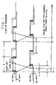
- FIG. 1 A typical startup sequence that illustrates the present invention is shown in FIG. 1.
- the first transceiver is activated, and transmits a start signal, typically a multi-bit data packet having a time duration P .
- This packet traverses the communication channel and arrives at the second transceiver after a propagation delay of a .
- the first transceiver activates its receiver, which listens for an incoming start signal for a listening period having duration L . (For simplicity of illustration, no waiting period to allow reflections to die out is included prior to activating the receiver).
- the start signal is the combination of the "start" and "stop" bits of the packet in this illustrative case, but may be any desired sequence of bits in the packet.
- the first transceiver again transmits a packet at time T2.
- the second transceiver is activated at time T1, which is S1 later than the activation of the first transceiver.
- the second transceiver After the transmission of its packet, the second transceiver also listens for a listening period. As shown, no start signal is received during this time either. Hence, the second transceiver again transmits a packet at time T3.
- a start signal will be received by one of the transceivers during its listening period.
- the transceiver detects the start signal, terminates the listening period and (after the optional waiting period R) starts transmitting a packet to the other transceiver.
- the transceivers are synchronized. Thereafter, a number of packets containing a fixed bit pattern may be exchanged between the transceivers, to verify proper synchronization. Each transceiver then switches to a state receptive to transmit and receive the user data.
- the transceivers are typically designed to reset L to the longer period when power is lost.
- the local time base of each transceiver uses a crystal oscillator having a design frequency of 1 megahertz and a tolerance of 0.01 percent, the time bases will differ in frequency by no more than 200 hertz. However, there is some difference, due to the inevitable statistical variations in the component values or operating conditions (e.g., temperature or power supply voltage) of the two transceivers. Because of this relatively small but inevitable difference in frequency, after a certain time period the transmissions from one of the transceivers will diverge sufficiently from the transmissions from the other transceiver that the transmissions will not overlap. (A resistance-capacitance type oscillator may be used to provide a larger tolerance, and shorter start-up time).
- the transmission of the start signal from transceiver one will eventually arrive at transceiver two during transceiver two's listening period.
- the listening period is a random variable that is chosen to be greater than a desired minimum time. However, it is desirable that it not be excessively long, in order to minimize the time required for start-up.
- a "randomizing" circuit is used that produces relatively larger variations in the listening period without affecting the frequency of the time base oscillator. This is effective because a change in the listening period also produces a change in the time interval between the periodic transmissions of the start signal. Hence, the statistical difference between the transmission intervals for the two transceivers is increased. In this manner, the average time required for start-up is reduced, while allowing for ease of maintaining synchronization of a high data rate after start-up is achieved. If the communications channel is broken or otherwise interfered with, the startup sequence will again be initiated, since a given transceiver will not then have received a signal within its listening time period. Hence, communication may again be established.
- the communication can appear to be full duplex to the user.
- the actual half-duplex data rate may be about 600 kilobits per second in each direction, which will allow each end user to send and receive at a constant 19 kilobit rate, allowing for oversampling the user data, the inclusion of control bits, and propagation delays.
- the data buffer has sufficient capacity, even momentary breaks in the communication channel need not be apparent to the users, since the transceivers can automatically re-initiate the above startup procedure until synchronization is again achieved, and re-transmit the missing data.
- an additional waiting period may be provided by each transceiver to allow reflections to die out in the channel before the transceiver transmits after receiving a transmission from the other end.
- Reflections are commonly present on a communication channel due to irregularities in the transmission medium at various points, usually including splices and equipment terminations. The irregularities include impedance mis-matches in the case of electrical conductors, and differences in the index of refraction in the case of optical conductors. Any reflections of a transmitted signal (from the near end) tend to mask the signal received from the far end.
- this additional waiting period is optional insofar as the present invention is concerned. That is, the reflections may not be of sufficient magnitude to interfere with the desired signal, or may be removed by echo-cancelers or dealt with otherwise.
- the "begin” step may occur when power is applied to the transceiver, and normally occurs independently for the two transceivers at opposite ends of a given channel.
- the transmitter then sends out the start signal (e.g., a multi-bit packet), while the receiver is disabled.
- the inclusion of an optional waiting period to allow reflections to be ignored is provided by adding a time period R before enabling the receiver.
- the waiting period is typically of duration 2A, wherein A is the propagation time of a signal over the maximum length communication channel with which the transceiver is designed to operate. For a local area type transmission system, the length is typically less than 10 kilometers.
- the present technique may be practiced with channels of any length.
- the round trip time (2A) then allows for a reflection from the far end of a channel having the maximum length (or less) to be ignored by the receiver.
- other waiting periods may be suitable. For example, a shorter waiting period may be acceptable if it is known that the far end reflection is relatively small in magnitude, or if the channel actually used is less than the maximum design length.
- the waiting period R may be longer than 2A if additional attenuation of reflections is desired.
- the listening period Upon enabling the receiver after this first optional waiting period, the listening period begins. If a start signal is not detected during the listening period, the transmitter again transmits a start signal. However, when a start signal is detected during the listening period, synchronization (i.e., "link-up") is achieved. Note that if the first optional waiting period is included, then a second waiting period, typically also of duration R, may be provided after detecting the start signal and before enabling the transmitter. The second waiting period allows for communicating over channels of less than the maximum length. Otherwise data could be lost, since the transceiver at the other end of the channel is then disabled from receiving during its first optional waiting period, in order to allow the reflection to be ignored at the far end in a comparable manner as above. By making the second optional waiting period to be equal to the first, it is not necessary to specify a minimum length for the channel.
- each transceiver utilizes a single light emitting diode (the "diode") for both transmitting optical signals, and also for receiving optical signals, by employing the diode as a photodetector, according to principles known in the art.
- a separate optical source e.g., laser or light emitting diode
- a separate photodetector e.g., pin diode, avalanche diode, phototransistor, etc.
- the two transceivers communicate via an optical fiber channel.
- the analog receiver amplifies the electrical signals from the diode during reception of optical signals, and supplies the amplified signal to the digital receiver, which is under the control of the protocol controller.
- the digital receiver operates on the data packets received, and converts the packets to a form suitable to the user via the "data out" line, along with a control signal to indicate the reception of the word. For example, if the user data is oversampled and encoded, then the digital receiver may convert the data back to its original form.
- a digital transmitter also under the control of the protocol controller, receives data and control signals from a desired data source, and provides suitably formatted data packets to the analog transmitter.
- the analog transmitter provides sufficient current amplification to drive the diode so as to generate the optical signal for transmission.
- a time base oscillator provides timing signals, and a randomizer circuit increases the randomness of the listening period over the randomness of the local time base, as discussed below.
- all of the circuitry with the exception of the diode (and quartz crystal - not shown), is located on a single integrated circuit. However, it may be advantageous in some cases to integrate the analog portions of the circuitry on one integrated circuit, and the digital portions on another integrated circuit, to allow for optimized processing for each.
- the protocol controller implements the protocol shown in FIG. 2 by control signals as follows: ARS Analog Receive Set: When this line is high the receiver is in its active state ready to receive data from the diode. When ARS is low then the receiver is in a state where it holds the receive detection threshold to avoid having it upset by the much larger transmit signals.
- Link Status This line goes high to signify that communications has been established. When Link Status is high then it will go low if a packet is not received within the listening period.
- RC Receive Control This line goes high to enable the Digital Receiver. When low, it clears the circuitry of the Digital Receiver. When the Protocol Controller sees that RO has gone high (signifying that the Digital Receiver has received a data packet from the fiber) then RC will go low after about 10 ⁇ S. This delay allows sufficient time for the packet to be decoded and loaded into the 31 bit receiver register.
- RO Receive Over The Digital Receiver causes this line to go high immediately after it has received a valid packet from the fiber. RO can only go high when RC is high.
- XC Transmit Control This line goes high to enable the Digital Transmitter. It is actually the clear control for the blocks within the Digital Transmitter. When the Protocol Controller sees that XO has gone high (signifying that the Digital Transmitter is finished) then XC will go low after a period defined by the time base (139.7 nanoseconds).
- XO Transmit Over The Digital Transmitter causes this line to go high only after it has finished sending a packet of data onto the fiber. XO can only go high when XC is high.
- each transceiver includes a randomizer circuit. This substantially increases the random variation of the listening time from one transceiver to another, as compared to the random variation due to the local time base, but without affecting the frequency of the local time base.
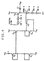
- a suitable circuit is shown in FIG. 4, wherein the well-known variability of the characteristics of field effect transistors is used for this purpose.
- the power supply voltage is imposed across series connected devices M1 and M2, which are gate-drain shorted.
- Transistors M2-M3 and M4-M5 form a current mirror that divides the current I1 to a smaller value.
- the delay ranges from about 100 microseconds to 2 milliseconds over expected variations in manufacturing tolerances, temperature, and power supply voltage.
- Other randomizing circuits may be used, or a pseudo-random number generator may be used for the randomizing function. Additionally, relying on electrical noise (e.g., a noisy diode) may provide this function, with still other techniques possible.
- the exemplary embodiment has illustrated signals in multiple-bit packets having equal bit lengths, it is alternately possible to employ packets having different bit lengths. For example, if information traffic is heavier in a given direction, then a larger transmit packet (i.e., having more bits) may be used in that direction. It is also possible to dynamically alter the packet length, to optimize the information carrying capacity of the system as the information load changes. On the other hand, in very simple, low-cost systems, the transceivers may employ only a single bit packet.
- pulse width modulation may be used, wherein a logic "1” is represented by a signal having a given duration (e.g., one microsecond), and a logic "0" is represented by a signal having another duration (e.g., two microseconds).
- a logic "1" is represented by a signal having a given duration (e.g., one microsecond)
- a logic "0" is represented by a signal having another duration (e.g., two microseconds).
- the next received signal (either a "1” or "0") may then be used as the start signal in the startup procedure noted above.
- the startup signal may be a multiple-bit packet having a different number of bits than an information bit packet.
- start signal illustrated above includes start and stop bits in a packet, the start signal may be readily implemented with Manchester encoded data by recognizing a 0 to 1 transition, without the inclusion of a stop bit. Other start signal schemes are also possible.
- Means may also be included in the transceiver to determine the actual propagation time (a) for the channel in use (as opposed to the assumed maximum time A), and adjust the length of the information packet, or period between packets accordingly, after start-up is achieved. Also, once the link is established, a measure of the actual propagation time (a) may advantageously be used to keep the receiver of a given transceiver disabled following a transmission by its transmitter until just prior to the time a return packet (from the other transceiver) is expected. This reduces the possibility that noise will be mistaken for an information signal. While a given transceiver may be designated to work with a channel having a given maximum propagation time (A), this need not be the case.
- a channel of arbitrary length may be used, with the transceiver data rate from the user being reduced accordingly as the channel length (and propagation time) increases. This may be accommodated automatically if desired by sending a signal to the near-end user when a return packet is received from the far end.
- the minimum listening period is then desirably less than 2A + P.
Claims (8)
- Un émetteur-récepteur conçu pour communiquer au moyen d'un canal, cet émetteur-récepteur comprenant un émetteur ("EMETTEUR NUMERIQUE"; "EMETTEUR ANALOGIQUE") conçu pour émettre de l'information avec un débit qui est commandé par une base de temps locale ("BASE DE TEMPS"), un récepteur ("RECEPTEUR NUMERIQUE"; "RECEPTEUR ANALOGIQUE") conçu pour recevoir de l'information, et des moyens facultatifs pour établir une période d'attente facultative (R) qui permet de ne pas prendre en compte au moins une réflexion qui résulte de l'information émise, CARACTERISE PAR des moyens pour émettre un signal ce début sortant, des moyens pour déterminer si un signal de début entrant est reçu pendant une période d'écoute ayant une durée L qui suit la période d'émission et d'attente facultative, des moyens pour mettre fin à la période d'attente avant L si un signal de début entrant est reçu, et des moyens pour faire en sorte que l'émetteur émette à nouveau un signal de début sortant si un signal de début entrant n'est pas reçu pendant la période d'attente, cette période d'attente étant une variable aléatoire qui est comprise entre des limites désirées.
- Un émetteur-récepteur selon la revendication 1, comprenant des moyens pour élaborer, à partir de la base de temps locale, une valeur minimale pour la période d'attente.
- Un émetteur-récepteur selon la revendication 2, dans lequel la valeur minimale est au moins égale à la durée du signal de début entrant.
- Un émetteur-récepteur selon la revendication 3, conçu pour communiquer au moyen d'un canal ayant un temps de propagation maximal (A), et dans lequel la valeur minimale précitée est la durée du signal de début entrant, plus deux fois le temps de propagation maximal de ce canal.
- Un émetteur-récepteur selon la revendication 1, 2, 3 ou 4, comprenant des moyens de randomisation ("CIRCUIT DE RANDOMISATION") qui augmentent notablement le caractère aléatoire de la période d'écoute, sans affecter la fréquence de la base de temps locale.
- Un émetteur-récepteur selon la revendication 1, 2, 3 ou 4, dans lequel la période d'écoute dépend essentiellement de la fréquence de la base de temps locale.
- Un émetteur-récepteur selon l'une quelconque des revendications précédentes, dans lequel les moyens destinés à émettre un signal de début sont conçus pour émettre un paquet à plusieurs bits ayant une configuration de bits donnée, et les moyens destinés à déterminer si un signal de début entrant est reçu, sont conçus pour reconnaître cette configuration de bits données.
- Un émetteur-récepteur selon l'une quelconque des revendications précédentes, dans lequel la durée du signal de début sortant est égale à la durée du signal de début entrant.
Applications Claiming Priority (2)
| Application Number | Priority Date | Filing Date | Title |
|---|---|---|---|
| US06/857,144 US4740992A (en) | 1986-04-29 | 1986-04-29 | Peer relationship transceiver |
| US857144 | 1986-04-29 |
Publications (3)
| Publication Number | Publication Date |
|---|---|
| EP0245972A2 EP0245972A2 (fr) | 1987-11-19 |
| EP0245972A3 EP0245972A3 (en) | 1989-10-18 |
| EP0245972B1 true EP0245972B1 (fr) | 1993-08-11 |
Family
ID=25325292
Family Applications (1)
| Application Number | Title | Priority Date | Filing Date |
|---|---|---|---|
| EP87303452A Expired - Lifetime EP0245972B1 (fr) | 1986-04-29 | 1987-04-21 | Emetteur-récepteur pour canal de communication |
Country Status (7)
| Country | Link |
|---|---|
| US (1) | US4740992A (fr) |
| EP (1) | EP0245972B1 (fr) |
| JP (1) | JPS62278842A (fr) |
| KR (1) | KR950004876B1 (fr) |
| CN (1) | CN1011014B (fr) |
| CA (1) | CA1271536A (fr) |
| DE (1) | DE3786950T2 (fr) |
Families Citing this family (18)
| Publication number | Priority date | Publication date | Assignee | Title |
|---|---|---|---|---|
| GB9112180D0 (en) * | 1991-06-06 | 1991-07-24 | British Telecomm | Communications network and method |
| EP0622940A1 (fr) * | 1993-04-28 | 1994-11-02 | Siemens Aktiengesellschaft | Procédé de mise en modes complémentaires de dispositifs de transmission connectés par une liaison fixe |
| US5544323A (en) * | 1993-09-23 | 1996-08-06 | Standard Microsystems Corp. | High bit rate ethernet connection |
| JP3437070B2 (ja) * | 1997-10-20 | 2003-08-18 | 富士通株式会社 | 加入者無線アクセスシステム |
| US6218274B1 (en) * | 1997-10-28 | 2001-04-17 | Sony Corporation | Semiconductor device and manufacturing method thereof |
| GB2356525B (en) * | 1999-11-08 | 2002-01-09 | Motorola Israel Ltd | Method of resolving collisions in direct mode operation |
| US7158574B2 (en) * | 2001-01-12 | 2007-01-02 | Silicon Laboratories Inc. | Digital interface in radio-frequency apparatus and associated methods |
| DE10113716C2 (de) * | 2001-03-19 | 2003-05-08 | Balluff Gmbh | Kommunikations-Schnittstelle für eine Wegmeßeinrichtung |
| CA2348242A1 (fr) * | 2001-05-23 | 2002-11-23 | Mediatrix Telecom Inc. | Gestionnaire d'appels multi-protocole |
| US8000278B2 (en) * | 2003-05-12 | 2011-08-16 | Intel Corporation | De-activation, at least in part, of receiver, in response, at least in part, to determination that an idle condition exists |
| US20040228341A1 (en) * | 2003-05-12 | 2004-11-18 | Avi Costo | De-activation, at least in part, of receiver, in response, at least in part, to determination that an idle condition exists |
| CN100334819C (zh) * | 2003-06-26 | 2007-08-29 | 北京瑞斯康达科技发展有限公司 | 以太网光纤收发器及用于该收发器的数据收发方法 |
| DE10339287A1 (de) * | 2003-08-27 | 2005-03-24 | Schütz, Thomas | Gerät oder Zusatzgerät zur automatischen Kontaktaufnahme |
| FR2862821B1 (fr) * | 2003-11-21 | 2006-04-07 | Atmel Nantes Sa | Procede et circuit electronique de decodage d'une trame asynchrone biphase dont la longueur n'est pas connue a l'avance, application, programme d'ordinateur et moyen de stockage correspondants |
| GB2413649A (en) * | 2004-04-29 | 2005-11-02 | Kevin John Kirk | Wireless transceiver remote control system |
| US7567517B2 (en) * | 2004-05-25 | 2009-07-28 | Intel Corporation | Performing channel analysis over a link |
| WO2013183140A1 (fr) * | 2012-06-07 | 2013-12-12 | 株式会社日立製作所 | Dispositif de commande de mouvement et procédé de communication correspondant |
| IT201900023460A1 (it) * | 2019-12-10 | 2021-06-10 | Comelit Group S P A | Metodo di gestione dello scambio di informazioni tra moduli di uno o più dispositivi attraverso un bus di tipo rs-485 |
Family Cites Families (5)
| Publication number | Priority date | Publication date | Assignee | Title |
|---|---|---|---|---|
| US4002847A (en) * | 1975-12-29 | 1977-01-11 | Bell Telephone Laboratories, Incorporated | Fault isolation in a serial-looped transmission system |
| JPS56117455A (en) * | 1980-02-22 | 1981-09-14 | Nippon Telegr & Teleph Corp <Ntt> | Transmission control system |
| JPS5745757A (en) * | 1980-09-03 | 1982-03-15 | Hitachi Ltd | Ring type communication system of equal level |
| JPS5842328A (ja) * | 1981-09-07 | 1983-03-11 | Hitachi Ltd | 遠隔折返し制御方式 |
| US4532626A (en) * | 1982-07-19 | 1985-07-30 | At&T Bell Laboratories | Collision avoiding system and protocol for a two path multiple access digital communications system |
-
1986
- 1986-04-29 US US06/857,144 patent/US4740992A/en not_active Expired - Lifetime
-
1987
- 1987-04-21 DE DE87303452T patent/DE3786950T2/de not_active Expired - Fee Related
- 1987-04-21 EP EP87303452A patent/EP0245972B1/fr not_active Expired - Lifetime
- 1987-04-28 CA CA000535798A patent/CA1271536A/fr not_active Expired - Fee Related
- 1987-04-28 CN CN87103125A patent/CN1011014B/zh not_active Expired
- 1987-04-28 JP JP62103428A patent/JPS62278842A/ja active Granted
- 1987-04-28 KR KR1019870004074A patent/KR950004876B1/ko not_active IP Right Cessation
Also Published As
| Publication number | Publication date |
|---|---|
| DE3786950T2 (de) | 1993-12-23 |
| JPH0552105B2 (fr) | 1993-08-04 |
| KR950004876B1 (ko) | 1995-05-15 |
| EP0245972A3 (en) | 1989-10-18 |
| CA1271536A (fr) | 1990-07-10 |
| KR870010704A (ko) | 1987-11-30 |
| CN87103125A (zh) | 1988-01-20 |
| EP0245972A2 (fr) | 1987-11-19 |
| JPS62278842A (ja) | 1987-12-03 |
| CN1011014B (zh) | 1990-12-26 |
| DE3786950D1 (de) | 1993-09-16 |
| US4740992A (en) | 1988-04-26 |
Similar Documents
| Publication | Publication Date | Title |
|---|---|---|
| EP0245972B1 (fr) | Emetteur-récepteur pour canal de communication | |
| KR910009666B1 (ko) | 정보 패킷 전송방법 및 송수신기 | |
| US5434861A (en) | Deterministic timed bus access method | |
| EP0475681B1 (fr) | Commande d'antenne pour réseau local sans fil | |
| US5828663A (en) | Access control system for wireless-lan terminals | |
| US4750171A (en) | Data switching system and method | |
| US4701909A (en) | Collision detection technique for an optical passive star local area network using CSMA/CD | |
| EP1219047B1 (fr) | Reseau bande de base sans fil assurant des transmissions isochrones | |
| EP0632619B1 (fr) | Procédé pour la réduction de collisions dans un réseau Ethernet | |
| GB2166328A (en) | In-house distribution facility for a broadband communication system | |
| JPH0666782B2 (ja) | 赤外線デ−タ通信方法 | |
| US4631718A (en) | Method and device for synchronization of system timing | |
| US4888763A (en) | Method and apparatus for detecting the collision of data packets utilizing a preassigned transceiver code in the preamble | |
| US4815070A (en) | Node apparatus for communication network having multi-conjunction architecture | |
| US4807258A (en) | Method for synchronizing a digital communication system | |
| MXPA97001756A (en) | A method to adapt a sync transmission | |
| US4843605A (en) | Node apparatus for communication network having multi-conjunction architecture | |
| WO1996008901A1 (fr) | Procede d'adaptation d'une transmission synchrone | |
| JPH0362063B2 (fr) | ||
| JP3722358B2 (ja) | 半二重光無線通信システム | |
| FI112548B (fi) | Järjestelmä datan siirtoa varten | |
| WO1990009068A1 (fr) | Procede ameliore d'acces synchronise deterministe a un bus | |
| JP2886273B2 (ja) | 通信制御装置 | |
| Pomalaza-Raez | Performance of a channel access protocol for FH-SS packet radio networks | |
| JPH0362062B2 (fr) |
Legal Events
| Date | Code | Title | Description |
|---|---|---|---|
| PUAI | Public reference made under article 153(3) epc to a published international application that has entered the european phase |
Free format text: ORIGINAL CODE: 0009012 |
|
| AK | Designated contracting states |
Kind code of ref document: A2 Designated state(s): DE FR GB IT NL |
|
| PUAL | Search report despatched |
Free format text: ORIGINAL CODE: 0009013 |
|
| AK | Designated contracting states |
Kind code of ref document: A3 Designated state(s): DE FR GB IT NL |
|
| 17P | Request for examination filed |
Effective date: 19900410 |
|
| 17Q | First examination report despatched |
Effective date: 19920205 |
|
| GRAA | (expected) grant |
Free format text: ORIGINAL CODE: 0009210 |
|
| AK | Designated contracting states |
Kind code of ref document: B1 Designated state(s): DE FR GB IT NL |
|
| ET | Fr: translation filed | ||
| REF | Corresponds to: |
Ref document number: 3786950 Country of ref document: DE Date of ref document: 19930916 |
|
| ITF | It: translation for a ep patent filed |
Owner name: MODIANO & ASSOCIATI S.R |
|
| PLBE | No opposition filed within time limit |
Free format text: ORIGINAL CODE: 0009261 |
|
| STAA | Information on the status of an ep patent application or granted ep patent |
Free format text: STATUS: NO OPPOSITION FILED WITHIN TIME LIMIT |
|
| RAP4 | Party data changed (patent owner data changed or rights of a patent transferred) |
Owner name: AT&T CORP. |
|
| 26N | No opposition filed | ||
| PGFP | Annual fee paid to national office [announced via postgrant information from national office to epo] |
Ref country code: FR Payment date: 20010322 Year of fee payment: 15 |
|
| PGFP | Annual fee paid to national office [announced via postgrant information from national office to epo] |
Ref country code: GB Payment date: 20010326 Year of fee payment: 15 |
|
| PGFP | Annual fee paid to national office [announced via postgrant information from national office to epo] |
Ref country code: NL Payment date: 20010327 Year of fee payment: 15 |
|
| PGFP | Annual fee paid to national office [announced via postgrant information from national office to epo] |
Ref country code: DE Payment date: 20010629 Year of fee payment: 15 |
|
| REG | Reference to a national code |
Ref country code: GB Ref legal event code: IF02 |
|
| PG25 | Lapsed in a contracting state [announced via postgrant information from national office to epo] |
Ref country code: GB Free format text: LAPSE BECAUSE OF NON-PAYMENT OF DUE FEES Effective date: 20020421 |
|
| PG25 | Lapsed in a contracting state [announced via postgrant information from national office to epo] |
Ref country code: NL Free format text: LAPSE BECAUSE OF NON-PAYMENT OF DUE FEES Effective date: 20021101 Ref country code: DE Free format text: LAPSE BECAUSE OF NON-PAYMENT OF DUE FEES Effective date: 20021101 |
|
| GBPC | Gb: european patent ceased through non-payment of renewal fee |
Effective date: 20020421 |
|
| PG25 | Lapsed in a contracting state [announced via postgrant information from national office to epo] |
Ref country code: FR Free format text: LAPSE BECAUSE OF NON-PAYMENT OF DUE FEES Effective date: 20021231 |
|
| NLV4 | Nl: lapsed or anulled due to non-payment of the annual fee |
Effective date: 20021101 |
|
| REG | Reference to a national code |
Ref country code: FR Ref legal event code: ST |
|
| PG25 | Lapsed in a contracting state [announced via postgrant information from national office to epo] |
Ref country code: IT Free format text: LAPSE BECAUSE OF NON-PAYMENT OF DUE FEES;WARNING: LAPSES OF ITALIAN PATENTS WITH EFFECTIVE DATE BEFORE 2007 MAY HAVE OCCURRED AT ANY TIME BEFORE 2007. THE CORRECT EFFECTIVE DATE MAY BE DIFFERENT FROM THE ONE RECORDED. Effective date: 20050421 |