EP0245761B1 - Manschettenförmige Entstörabschmirmung für Zündverteiler an Brennkraftmaschinen - Google Patents
Manschettenförmige Entstörabschmirmung für Zündverteiler an Brennkraftmaschinen Download PDFInfo
- Publication number
- EP0245761B1 EP0245761B1 EP87106545A EP87106545A EP0245761B1 EP 0245761 B1 EP0245761 B1 EP 0245761B1 EP 87106545 A EP87106545 A EP 87106545A EP 87106545 A EP87106545 A EP 87106545A EP 0245761 B1 EP0245761 B1 EP 0245761B1
- Authority
- EP
- European Patent Office
- Prior art keywords
- carrier material
- sleeve
- interference suppressor
- electrically conductive
- suppressor according
- Prior art date
- Legal status (The legal status is an assumption and is not a legal conclusion. Google has not performed a legal analysis and makes no representation as to the accuracy of the status listed.)
- Expired - Lifetime
Links
- 238000002485 combustion reaction Methods 0.000 title claims description 3
- 230000001629 suppression Effects 0.000 title description 4
- 239000012876 carrier material Substances 0.000 claims description 56
- 229910052751 metal Inorganic materials 0.000 claims description 24
- 239000002184 metal Substances 0.000 claims description 24
- 239000011888 foil Substances 0.000 claims description 21
- 239000011248 coating agent Substances 0.000 claims description 11
- 238000000576 coating method Methods 0.000 claims description 11
- 229920001971 elastomer Polymers 0.000 claims description 8
- 239000004033 plastic Substances 0.000 claims description 7
- 229920003023 plastic Polymers 0.000 claims description 7
- 239000004744 fabric Substances 0.000 claims description 4
- 229920002379 silicone rubber Polymers 0.000 claims description 4
- 238000010276 construction Methods 0.000 claims description 3
- 239000000806 elastomer Substances 0.000 claims description 3
- 230000000149 penetrating effect Effects 0.000 claims description 3
- RYGMFSIKBFXOCR-UHFFFAOYSA-N Copper Chemical compound [Cu] RYGMFSIKBFXOCR-UHFFFAOYSA-N 0.000 claims description 2
- 229910045601 alloy Inorganic materials 0.000 claims description 2
- 239000000956 alloy Substances 0.000 claims description 2
- 229910052782 aluminium Inorganic materials 0.000 claims description 2
- XAGFODPZIPBFFR-UHFFFAOYSA-N aluminium Chemical compound [Al] XAGFODPZIPBFFR-UHFFFAOYSA-N 0.000 claims description 2
- 229910052802 copper Inorganic materials 0.000 claims description 2
- 239000010949 copper Substances 0.000 claims description 2
- 150000002739 metals Chemical class 0.000 claims description 2
- 229910052709 silver Inorganic materials 0.000 claims description 2
- 239000004332 silver Substances 0.000 claims description 2
- HCHKCACWOHOZIP-UHFFFAOYSA-N Zinc Chemical compound [Zn] HCHKCACWOHOZIP-UHFFFAOYSA-N 0.000 claims 1
- 239000004411 aluminium Substances 0.000 claims 1
- 239000004020 conductor Substances 0.000 claims 1
- 229910052725 zinc Inorganic materials 0.000 claims 1
- 239000011701 zinc Substances 0.000 claims 1
- 239000000463 material Substances 0.000 description 11
- 238000004519 manufacturing process Methods 0.000 description 5
- 238000009413 insulation Methods 0.000 description 3
- 238000004026 adhesive bonding Methods 0.000 description 2
- 238000004873 anchoring Methods 0.000 description 2
- 239000011810 insulating material Substances 0.000 description 2
- 239000002985 plastic film Substances 0.000 description 2
- 229920006255 plastic film Polymers 0.000 description 2
- 238000000926 separation method Methods 0.000 description 2
- XLYOFNOQVPJJNP-UHFFFAOYSA-N water Substances O XLYOFNOQVPJJNP-UHFFFAOYSA-N 0.000 description 2
- BQCADISMDOOEFD-UHFFFAOYSA-N Silver Chemical compound [Ag] BQCADISMDOOEFD-UHFFFAOYSA-N 0.000 description 1
- ATJFFYVFTNAWJD-UHFFFAOYSA-N Tin Chemical compound [Sn] ATJFFYVFTNAWJD-UHFFFAOYSA-N 0.000 description 1
- 230000007797 corrosion Effects 0.000 description 1
- 238000005260 corrosion Methods 0.000 description 1
- 230000009977 dual effect Effects 0.000 description 1
- 230000005489 elastic deformation Effects 0.000 description 1
- 239000012799 electrically-conductive coating Substances 0.000 description 1
- 238000010030 laminating Methods 0.000 description 1
- 210000002414 leg Anatomy 0.000 description 1
- 239000007788 liquid Substances 0.000 description 1
- 229910052718 tin Inorganic materials 0.000 description 1
- 239000011135 tin Substances 0.000 description 1
- 210000000689 upper leg Anatomy 0.000 description 1
Images


Classifications
-
- H—ELECTRICITY
- H05—ELECTRIC TECHNIQUES NOT OTHERWISE PROVIDED FOR
- H05K—PRINTED CIRCUITS; CASINGS OR CONSTRUCTIONAL DETAILS OF ELECTRIC APPARATUS; MANUFACTURE OF ASSEMBLAGES OF ELECTRICAL COMPONENTS
- H05K9/00—Screening of apparatus or components against electric or magnetic fields
- H05K9/0007—Casings
-
- F—MECHANICAL ENGINEERING; LIGHTING; HEATING; WEAPONS; BLASTING
- F02—COMBUSTION ENGINES; HOT-GAS OR COMBUSTION-PRODUCT ENGINE PLANTS
- F02P—IGNITION, OTHER THAN COMPRESSION IGNITION, FOR INTERNAL-COMBUSTION ENGINES; TESTING OF IGNITION TIMING IN COMPRESSION-IGNITION ENGINES
- F02P7/00—Arrangements of distributors, circuit-makers or -breakers, e.g. of distributor and circuit-breaker combinations or pick-up devices
- F02P7/02—Arrangements of distributors, circuit-makers or -breakers, e.g. of distributor and circuit-breaker combinations or pick-up devices of distributors
- F02P7/021—Mechanical distributors
- F02P7/025—Mechanical distributors with noise suppression means specially adapted for the distributor
Definitions
- the invention relates to an interference shield for ignition distributors on internal combustion engines, consisting of a flexible, electrically conductive sleeve with at least one layer of carrier material, which is foldable and whose lateral edge surfaces have connecting parts and can be releasably connected to one another, the lateral edge surfaces lying against one another in the assembled state and the cuff encloses the distributor and its lines in the mouth area.
- the sleeve of an interference suppressor known from EP-A1-75 263 of the type mentioned initially consists of an electrically conductive silicone elastomer and is correspondingly expensive in terms of material (cf. also DE-GM 81 27 135).
- the required strength which must also be provided in particular on the lateral edge surfaces which have the fastening means, the sleeve must inevitably be designed with an appropriate thickness, which leads to relatively high material costs.
- GB-A-573 660 describes a shield which consists of low-resistance rubber material and, in the absence of insulation of the part to be shielded, can additionally have an inner layer of normal rubber in order to ensure the lack of insulation. If the part to be shielded is already insulated, the shielding can consist entirely of low-resistance rubber material. In both cases, the low-resistance rubber material itself also forms the support for the shield.
- the shielding housing is made of metal, apart from an end cover which carries contacts such as brush elements and is therefore inevitably made of insulating material.
- a thin, corresponding recesses for the contacts and the like are provided on the outer surface of the lid, which is made of insulating material and is not foldable and not foldable and serves primarily to mutually isolate a plurality of contacts and the like.
- US-A-1 987 755 describes a shield in which the electrically conductive layer is formed as a metal wire mesh in order to produce the required strength.
- the required strength of the shield is again achieved in this case by the electrically conductive layer itself, while the rubber jacket is only provided for insulation purposes.
- the aim of the invention is to provide an interference suppression shield of the type mentioned at the outset consisting of a flexible, foldable and closable cuff on the lateral edge surfaces, which is simple and inexpensive to manufacture and therefore suitable for mass production and is easy to handle, and which nevertheless both Desired high electrical conductivity as well as the high strength required in view of the particular stresses occurring in such a sleeve.
- the carrier material of the sleeve is electrically non-conductive and consists of tissue, plastic film or the like, that a separate electrically conductive pad or insert is fixed to the layer or between the layers of carrier material, and that Backing material and the support or insert are spanned at points with fastening elements which also carry a connecting part of the releasable cuff edge connection.
- the multilayer structure reduces the manufacturing costs to be expected, since according to the invention the carrier material can be designed completely independently of the conductive pad or insert, i.e. is chosen with a view to the highest possible strength, while cheaper materials with lower strength, such as, for example, a simple metal foil, can be used for the conductive support or insert.
- the layer of carrier material can in particular also be selected with a view to the best possible mechanical protection and / or corrosion protection, in particular water shielding.
- the carrier material is preferably on the outside when the sleeve is folded.
- the sleeve is constructed in three layers from two layers of carrier material and an electrically conductive insert or coating in between.
- the layers of carrier material are preferably permanently connected to one another at the edge, in particular sewn or glued.
- a push button arrangement is advantageously provided as the cuff edge connection, the connecting parts carried by the fastening elements being formed by the head and the associated receiving bushing of the push button arrangement.
- the fasteners take over the double function already mentioned in a particularly advantageous manner.
- other connection forms in particular a Velcro fastener, can be provided on the edge of the cuff instead of a push-button connection.
- the fastening elements are expediently constructed from two half-parts, each of which has a plate-shaped contact section and can be locked together by means of a shaft penetrating the sleeve.
- the shaft can be arranged on the contact section of one half part and engage in a socket connected to the other half part.
- the fasteners are preferably made of plastic.
- the cuff can expediently be provided with a ground strap which is in contact with the electrically conductive support, insert or coating and can be attached to the cuff by means of a fastening element.
- This ground strap can also be covered with the fastening elements mentioned, which form a push-button arrangement, and can be closed to form a ring.
- the ground strap can in particular consist of an electrically conductive plastic or electrically conductive elastomer, for example a silicone elastomer. It should then have an overall sufficient degree of elasticity so that it can be clamped around an engine or body part that is electrically grounded, which results in a flat system and a low contact resistance.
- the ground strap can also consist of a strip of carrier material with an electrically conductive support or coating, the support advantageously being able to be connected point by point to the carrier material, preferably with a fastening element at only a single point. This advantageously separates the function of an electrically well-conductive contact strip and an elastic band used to stretch the contact strip.
- the carrier material used for the cuff itself and the corresponding electrically conductive support, insert or coating of the cuff according to the invention are, on the other hand, necessarily flexible, that is to say flexible, but not necessarily elastic.
- the sleeve 10 of the interference shield for ignition distributors shown in FIG. 1 has an essentially trapezoidal outline in the unfolded state.
- the edge 12 of the sleeve 10 on the trapezoidal base is convexly curved outwards.
- the corners of the cuff 10 are rounded.
- the cuff 10 can be folded along a transverse central plane, its half parts essentially coinciding with one another, and closed at the edge with push buttons. Head parts 14 and associated socket parts 16 of the push button arrangement thus form connecting parts of a releasable cuff edge connection. Three push buttons are located on the thighs of the trapezoid, essentially uniformly distributed over their length, and a push button is arranged in the middle region of the shorter base line.
- the sleeve 10 is constructed in two layers. Their layer or layer lying outside in the buttoned state is formed by a carrier material 18 which is generally not electrically conductive.
- This carrier material 18 can be, for example, a fabric or a film, in particular a plastic film.
- the carrier material 18 can be impermeable to liquids in order to prevent water from entering the ignition distributor in the assembled state of the sleeve 10.
- a fabric can be impregnated in a suitable manner.
- the carrier material 18 has the function of covering and mechanically protecting an inner, electrically conductive support 20 of the sleeve 10.
- the electrically conductive pad 20 consists of a metal foil, which is a part separate from the carrier material 18 and has essentially the same floor plan according to FIG. 1.
- Aluminum, tin, copper or alloys of these metals are particularly suitable as the material of the film.
- the film can have a thin, in particular vapor-deposited or galvanically applied silver layer in order to ensure a high surface conductivity.
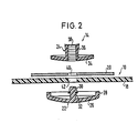
- the layer of carrier material 18 and the electrically conductive support 20 formed by a metal foil are clamped together according to FIG. 2 with fastening elements, to which the head part 14 or socket part 16 of the push-button arrangement is integrally formed at the same time.
- the fastening elements consist of two half-parts 22, 24.
- the half-part 22 coming to lie on the outside of the cuff 10 has an abutment section 26 which is circular in shape in the shape of a plate and has an axially raised edge 28.
- an integrally molded shaft 30 which projects in the axial direction and serves as an anchoring pin.
- This shaft 30 has latching means, which are represented in FIG.
- the half part 24 coming to lie on the inside of the cuff 10 has a plate-shaped contact section 34 which is also circular in plan and which, like the plate-shaped contact section 26 of the outer half part 22, is curved and fits into its plate opening.
- a socket 36 is integrally formed on the contact section 34 in a central arrangement and has an axial bore 38 penetrating the plate-shaped contact section 34.
- the axial bore 38 has latching means on its inner casing which cooperate with those on the shaft 30, for example in the form of a toothing with a plurality of successive steps in the axial direction, on which the head of the shaft 30 is held.
- the half parts 22, 24 of the connecting elements are preferably made of an elastic plastic. Your snap-in connection cannot be released with normal use of force.
- the layer of carrier material 18 and the film-like support 20 are clamped together with the half parts 22, 24 of the fastening elements.
- the shaft 30 serving as anchoring pin engages through aligned holes 40, 42 in the carrier material 18 or the support 20.
- the half parts 22, 24 are pressed together, for which a pair of pliers can be used.
- the head of the shaft 30 comes to lie in a suitable latching of the socket 36.
- the fastening elements or their half parts 22, 24 also form the push button arrangement for closing the cuff 10.
- the inner half part 24 of the fastening elements is designed either as a head part 14 or as a socket part 1 of the push button arrangement.
- Fig. 2 shows a head part 14, which is realized by a socket 36 which widens conically towards its free end.
- the associated socket part not shown, has a corresponding opening into which the socket 36 can be inserted with elastic deformation. The push button is then closed.
- the electrically conductive layer or overlay 20 of the sleeve 10 does not necessarily have to be connected to the layer of carrier material 18 only at individual points. Rather, a flat, positive connection is also possible, for example by gluing or laminating a metal foil onto the carrier material 18 as an electrically conductive pad 20.
- a ground strap 44, 46 is connected to the cuff 10 according to the invention, which is made up of a short section 44, which attaches to the long base side or to the edge 12 of the cuff 10, when looking at the inner surface thereof on the left about a quarter of the base length, and a long section 46.
- the extent of section 44 is essentially perpendicular to the base side or to the edge 12.
- This short section 44 of the earth strap 44, 46 is in contact with the electrically conductive system 20 of the sleeve 10. It is clamped to the cuff 10 with a fastening element 48, the push button part of which has no function.
- the long section 46 of the ground strap is clamped by means of a further fastening element 50, which includes a right angle with the short section 44.
- a fastening element 52 is provided, the push-button part of which cooperates with that of the fastening element 50, so that the long section 46 of the ground strap 44, 46 can be closed in an annular manner and buttoned together.
- the ground strap 44, 46 according to FIG. 1 is formed in one layer. It preferably consists of an electrically conductive plastic or elastomer, for example a silicone elastomer. At least the long section 46 of the ground strap 44, 46 should have a certain degree of elasticity so that it can be tensioned around a body part that is electrically grounded.
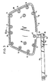
- FIG. 3 and 4 show, as a further exemplary embodiment, a three-layer interference suppression collar, in which an electrically conductive insert 58 is provided between two layers of carrier material 54, 56.
- the latter can in turn consist of a metal foil, while an electrically non-conductive fabric or the like is used for the carrier material. comes into consideration.
- the layers of carrier material 54, 56 and the insert 58 are clamped together with the already mentioned connecting parts 14, 16, which at the same time carry a push button arrangement for holding the folded cuff together.
- the layers of carrier material 54, 56 are congruent.
- the insert 58 has the same outline contour as the carrier material 54, 56, but is somewhat smaller, so that the carrier material 54, 56 protrudes all around the insert 58.
- the two layers of carrier material 54, 56 are sewn together at this protruding edge.
- the seam 60 runs all around and is only interrupted at the outlet of the earth strap.
- the protruding edges of the layers of carrier material 54, 56 can also be permanently connected to one another in another way, for example by gluing.
- the insert 58 is encased on all sides and optimally protected.
- the arrangement of the ground strap in Fig. 3 and Fig. 4 corresponds essentially to the previously discussed embodiment, only that Leaving the ground strap is closer to the transverse center line of the cuff 10.
- the ground strap is built up in two layers.
- the short ground strap section thus includes a short strip of carrier material 62 and a short strip of metal foil or electrically conductive pad 64.
- the long ground strap section is formed by a long strip of carrier material 66 and one end of metal foil or electrically conductive pad 68, the latter only forming over extends a relatively short piece of the long ground strap section.
- the width of the metal foil essentially corresponds to that of the strips of carrier material 62, 66.
- Metal foil or electrically conductive support 64, 68 and carrier material 62, 66 are clamped together with the fastening elements 48, 50, 52, which, as already with reference to FIG. 1 described, serve to attach the earth strap to the cuff and to close the earth strap in an annular manner.
- the electrically conductive support 64, 68 designed as a metal foil comes to lie on the inside of the ground strap, to which the view is directed in FIG. 3.
- Fig. 4 shows the necessary guidance of the metal foil on the fasteners 48, 50.
- the short strip of carrier material 62 comes with the short strip of electrically conductive pad 64 to lie between the layers of carrier material 54, 56 of the sleeve 10 in such a way that it consists of metal foil short strips of electrically conductive support touch the electrically conductive insert 58.
- a ground contact is thus produced by clamping together with the fastening element 48.
- the end consisting of metal foil wraps around the long strip of carrier material 66 and comes into contact with the short strip consisting of metal foil and electrically conductive support 64.
- the 90 ° angle of the ground strap does not appear in FIG. 4.
- the end of electrically conductive support 68 made of metal foil with the annularly closed, long strip of carrier material 66 is stretched against an engine or body part of the vehicle which is electrically grounded.
- the long strip of carrier material 66 is elastic to the extent necessary for this.
- the end of electrically conductive support 68 made of metal foil has no elastic properties. It is also connected to the long strip of carrier material 66 by means of the fastening element 50 at only a single point, so that the latter can easily be elastically stretched.
- the same, but also a different carrier material can be used for the ground strap than that provided for the rest of the cuff.
Landscapes
- Engineering & Computer Science (AREA)
- Microelectronics & Electronic Packaging (AREA)
- Chemical & Material Sciences (AREA)
- Combustion & Propulsion (AREA)
- Mechanical Engineering (AREA)
- General Engineering & Computer Science (AREA)
- Shielding Devices Or Components To Electric Or Magnetic Fields (AREA)
Applications Claiming Priority (2)
| Application Number | Priority Date | Filing Date | Title |
|---|---|---|---|
| DE19863616471 DE3616471A1 (de) | 1986-05-15 | 1986-05-15 | Manschettenfoermige entstoerabschirmung fuer zuendverteiler an brennkraftmaschinen |
| DE3616471 | 1986-05-15 |
Publications (2)
| Publication Number | Publication Date |
|---|---|
| EP0245761A1 EP0245761A1 (de) | 1987-11-19 |
| EP0245761B1 true EP0245761B1 (de) | 1990-10-03 |
Family
ID=6300949
Family Applications (1)
| Application Number | Title | Priority Date | Filing Date |
|---|---|---|---|
| EP87106545A Expired - Lifetime EP0245761B1 (de) | 1986-05-15 | 1987-05-06 | Manschettenförmige Entstörabschmirmung für Zündverteiler an Brennkraftmaschinen |
Country Status (3)
| Country | Link |
|---|---|
| EP (1) | EP0245761B1 (OSRAM) |
| DE (2) | DE3616471A1 (OSRAM) |
| ES (1) | ES2017957B3 (OSRAM) |
Families Citing this family (2)
| Publication number | Priority date | Publication date | Assignee | Title |
|---|---|---|---|---|
| DE3811216A1 (de) * | 1988-04-02 | 1989-10-19 | Bosch Gmbh Robert | Schutzkappe fuer zuendspulen - schaltgeraet - kombination |
| US11110779B2 (en) * | 2019-03-21 | 2021-09-07 | Webasto SE | Roller blind arrangement having a grounding element |
Family Cites Families (7)
| Publication number | Priority date | Publication date | Assignee | Title |
|---|---|---|---|---|
| US1987755A (en) * | 1933-10-06 | 1935-01-15 | Moyle S Skaer | Radio static shield |
| GB573660A (en) * | 1940-11-29 | 1945-11-30 | Joseph Jacob Davis | Improvements in and relating to the screening of electrical devices to prevent interference with wireless signals |
| FR1534024A (fr) * | 1967-06-14 | 1968-07-26 | Citroen Sa Andre | Dispositif d'anti-parasitage pour allumeur |
| DE2244583C3 (de) * | 1972-09-12 | 1979-11-29 | Robert Bosch Gmbh, 7000 Stuttgart | Kappe aus elektrischem Isolierstoff zum Abdecken eines Zündverteilerbzw. Zündspulengehäuses |
| DE2314460C3 (de) * | 1973-03-23 | 1981-11-26 | Robert Bosch Gmbh, 7000 Stuttgart | Entstörumhüllung für die ans elektrisch isolierendem Material bestehende Kappe des Zündverteilers der Zündanlage einer Brennkraftmaschine |
| DE8127135U1 (de) * | 1981-09-17 | 1982-04-01 | Adam Opel AG, 6090 Rüsselsheim | Entstörabschirmung für Zündverteiler an Brennkraftmaschinen |
| JPS60106344A (ja) * | 1983-11-11 | 1985-06-11 | Mabuchi Motor Co Ltd | 小型モ−タ |
-
1986
- 1986-05-15 DE DE19863616471 patent/DE3616471A1/de active Granted
-
1987
- 1987-05-06 DE DE8787106545T patent/DE3765307D1/de not_active Expired - Lifetime
- 1987-05-06 EP EP87106545A patent/EP0245761B1/de not_active Expired - Lifetime
- 1987-05-06 ES ES87106545T patent/ES2017957B3/es not_active Expired - Lifetime
Also Published As
| Publication number | Publication date |
|---|---|
| DE3616471A1 (de) | 1987-11-19 |
| DE3616471C2 (OSRAM) | 1990-04-26 |
| EP0245761A1 (de) | 1987-11-19 |
| DE3765307D1 (de) | 1990-11-08 |
| ES2017957B3 (es) | 1991-03-16 |
Similar Documents
| Publication | Publication Date | Title |
|---|---|---|
| DE102010037494A1 (de) | Lenkrad mit einem biometrischen Sensor | |
| DE102008049112A1 (de) | Textilelektrode | |
| DE69604999T2 (de) | Brückenverbinder | |
| EP3217158A1 (de) | Kapazitiver flächensensor | |
| DE2642887A1 (de) | Rotoranordnung und elektrischer schalter enthaltend eine derartige rotoranordnung | |
| DE7019640U (de) | Elektrischer streifenschalter. | |
| EP0653322B1 (de) | Lagerachse für eine Fahrzeugsonnenblende | |
| EP0088780A1 (de) | Schutzdecke. | |
| EP0155393B1 (de) | Hochfrequenzdichtung für Gehäuseverschlüsse und Türen | |
| DE1285232B (de) | Befestigungsknopf | |
| EP0245761B1 (de) | Manschettenförmige Entstörabschmirmung für Zündverteiler an Brennkraftmaschinen | |
| DE102023213369A1 (de) | Sensormatte zur Detektierung eines Berührungsobjektes an einer Lenkhandhabe eines Fahrzeugs sowie Lenkhandhabe für ein Fahrzeug | |
| DE7230513U (de) | Miniaturpotentiometer | |
| EP0581186B1 (de) | Wasserdichtes Kleidungsstück | |
| DE2926312C2 (OSRAM) | ||
| DE1244924B (de) | Elektrisches Bauelement mit drehbarer Betaetigungswelle, insbesondere Widerstand oder Schalter | |
| DE3785804T2 (de) | Komforme biomedizinische Flachelektrode. | |
| DE4037712C2 (de) | Fahrzeugantenne | |
| DE69501611T2 (de) | Montage-Einrichtung für ein Bündel elektrischer Leiter | |
| EP1495939B1 (de) | Fahrzeuglenkrad mit Heizelement | |
| EP0370224A2 (de) | Kontaktmatte für Fahrzeugsitze | |
| DE20112469U1 (de) | Elektrischer-Vierwege-Schalter | |
| DE69006474T2 (de) | Aeussere Schutzvorrichtung. | |
| DE1615646A1 (de) | Verbinder mit Filterwirkung | |
| DE102017130385A1 (de) | Elektrodenvorrichtung |
Legal Events
| Date | Code | Title | Description |
|---|---|---|---|
| PUAI | Public reference made under article 153(3) epc to a published international application that has entered the european phase |
Free format text: ORIGINAL CODE: 0009012 |
|
| AK | Designated contracting states |
Kind code of ref document: A1 Designated state(s): DE ES FR GB IT SE |
|
| 17P | Request for examination filed |
Effective date: 19880121 |
|
| 17Q | First examination report despatched |
Effective date: 19890411 |
|
| GRAA | (expected) grant |
Free format text: ORIGINAL CODE: 0009210 |
|
| ITF | It: translation for a ep patent filed | ||
| AK | Designated contracting states |
Kind code of ref document: B1 Designated state(s): DE ES FR GB IT SE |
|
| ET | Fr: translation filed | ||
| REF | Corresponds to: |
Ref document number: 3765307 Country of ref document: DE Date of ref document: 19901108 |
|
| GBT | Gb: translation of ep patent filed (gb section 77(6)(a)/1977) | ||
| PLBE | No opposition filed within time limit |
Free format text: ORIGINAL CODE: 0009261 |
|
| STAA | Information on the status of an ep patent application or granted ep patent |
Free format text: STATUS: NO OPPOSITION FILED WITHIN TIME LIMIT |
|
| 26N | No opposition filed | ||
| PGFP | Annual fee paid to national office [announced via postgrant information from national office to epo] |
Ref country code: SE Payment date: 19920318 Year of fee payment: 6 |
|
| PGFP | Annual fee paid to national office [announced via postgrant information from national office to epo] |
Ref country code: FR Payment date: 19920319 Year of fee payment: 6 |
|
| PGFP | Annual fee paid to national office [announced via postgrant information from national office to epo] |
Ref country code: GB Payment date: 19930413 Year of fee payment: 7 |
|
| PG25 | Lapsed in a contracting state [announced via postgrant information from national office to epo] |
Ref country code: SE Effective date: 19930507 |
|
| PGFP | Annual fee paid to national office [announced via postgrant information from national office to epo] |
Ref country code: ES Payment date: 19930519 Year of fee payment: 7 |
|
| PGFP | Annual fee paid to national office [announced via postgrant information from national office to epo] |
Ref country code: DE Payment date: 19930714 Year of fee payment: 7 |
|
| PG25 | Lapsed in a contracting state [announced via postgrant information from national office to epo] |
Ref country code: FR Effective date: 19940131 |
|
| REG | Reference to a national code |
Ref country code: FR Ref legal event code: ST |
|
| PG25 | Lapsed in a contracting state [announced via postgrant information from national office to epo] |
Ref country code: GB Effective date: 19940506 |
|
| PG25 | Lapsed in a contracting state [announced via postgrant information from national office to epo] |
Ref country code: ES Free format text: LAPSE BECAUSE OF NON-PAYMENT OF DUE FEES Effective date: 19940507 |
|
| GBPC | Gb: european patent ceased through non-payment of renewal fee |
Effective date: 19940506 |
|
| EUG | Se: european patent has lapsed |
Ref document number: 87106545.4 Effective date: 19931210 |
|
| PG25 | Lapsed in a contracting state [announced via postgrant information from national office to epo] |
Ref country code: DE Effective date: 19950201 |
|
| REG | Reference to a national code |
Ref country code: ES Ref legal event code: FD2A Effective date: 19990201 |
|
| PG25 | Lapsed in a contracting state [announced via postgrant information from national office to epo] |
Ref country code: IT Free format text: LAPSE BECAUSE OF NON-PAYMENT OF DUE FEES;WARNING: LAPSES OF ITALIAN PATENTS WITH EFFECTIVE DATE BEFORE 2007 MAY HAVE OCCURRED AT ANY TIME BEFORE 2007. THE CORRECT EFFECTIVE DATE MAY BE DIFFERENT FROM THE ONE RECORDED. Effective date: 20050506 |