EP0245737A1 - Corps en forme de nid d'abeilles, en particulier support pour catalyseur, avec des tôles métalliques superposées, repliées en boucles de sens contraire, et son procédé de fabrication - Google Patents
Corps en forme de nid d'abeilles, en particulier support pour catalyseur, avec des tôles métalliques superposées, repliées en boucles de sens contraire, et son procédé de fabrication Download PDFInfo
- Publication number
- EP0245737A1 EP0245737A1 EP87106405A EP87106405A EP0245737A1 EP 0245737 A1 EP0245737 A1 EP 0245737A1 EP 87106405 A EP87106405 A EP 87106405A EP 87106405 A EP87106405 A EP 87106405A EP 0245737 A1 EP0245737 A1 EP 0245737A1
- Authority
- EP
- European Patent Office
- Prior art keywords
- sheets
- stack
- honeycomb body
- catalyst carrier
- casing tube
- Prior art date
- Legal status (The legal status is an assumption and is not a legal conclusion. Google has not performed a legal analysis and makes no representation as to the accuracy of the status listed.)
- Granted
Links
- 239000003054 catalyst Substances 0.000 title claims abstract description 31
- 239000002184 metal Substances 0.000 title claims description 32
- 238000004519 manufacturing process Methods 0.000 title claims description 20
- 239000000945 filler Substances 0.000 claims abstract description 13
- 238000005516 engineering process Methods 0.000 claims abstract description 10
- 238000005304 joining Methods 0.000 claims abstract description 10
- 239000007789 gas Substances 0.000 claims abstract description 4
- 238000000034 method Methods 0.000 claims description 5
- 229910000679 solder Inorganic materials 0.000 claims description 5
- 230000001788 irregular Effects 0.000 claims description 4
- 230000006698 induction Effects 0.000 claims description 2
- 230000005855 radiation Effects 0.000 claims description 2
- 238000005476 soldering Methods 0.000 abstract description 5
- 241001016380 Reseda luteola Species 0.000 description 3
- 230000002349 favourable effect Effects 0.000 description 3
- 238000003780 insertion Methods 0.000 description 3
- 230000037431 insertion Effects 0.000 description 3
- 230000000694 effects Effects 0.000 description 2
- 206010047697 Volvulus Diseases 0.000 description 1
- 238000005452 bending Methods 0.000 description 1
- 238000005520 cutting process Methods 0.000 description 1
- 238000009826 distribution Methods 0.000 description 1
- 239000011888 foil Substances 0.000 description 1
- 239000006072 paste Substances 0.000 description 1
- 239000000843 powder Substances 0.000 description 1
- 238000004904 shortening Methods 0.000 description 1
- 239000007858 starting material Substances 0.000 description 1
- 230000008646 thermal stress Effects 0.000 description 1
- 238000003466 welding Methods 0.000 description 1
Images
Classifications
-
- B—PERFORMING OPERATIONS; TRANSPORTING
- B01—PHYSICAL OR CHEMICAL PROCESSES OR APPARATUS IN GENERAL
- B01J—CHEMICAL OR PHYSICAL PROCESSES, e.g. CATALYSIS OR COLLOID CHEMISTRY; THEIR RELEVANT APPARATUS
- B01J35/00—Catalysts, in general, characterised by their form or physical properties
- B01J35/50—Catalysts, in general, characterised by their form or physical properties characterised by their shape or configuration
- B01J35/56—Foraminous structures having flow-through passages or channels, e.g. grids or three-dimensional monoliths
-
- F—MECHANICAL ENGINEERING; LIGHTING; HEATING; WEAPONS; BLASTING
- F01—MACHINES OR ENGINES IN GENERAL; ENGINE PLANTS IN GENERAL; STEAM ENGINES
- F01N—GAS-FLOW SILENCERS OR EXHAUST APPARATUS FOR MACHINES OR ENGINES IN GENERAL; GAS-FLOW SILENCERS OR EXHAUST APPARATUS FOR INTERNAL COMBUSTION ENGINES
- F01N13/00—Exhaust or silencing apparatus characterised by constructional features ; Exhaust or silencing apparatus, or parts thereof, having pertinent characteristics not provided for in, or of interest apart from, groups F01N1/00 - F01N5/00, F01N9/00, F01N11/00
- F01N13/011—Exhaust or silencing apparatus characterised by constructional features ; Exhaust or silencing apparatus, or parts thereof, having pertinent characteristics not provided for in, or of interest apart from, groups F01N1/00 - F01N5/00, F01N9/00, F01N11/00 having two or more purifying devices arranged in parallel
- F01N13/017—Exhaust or silencing apparatus characterised by constructional features ; Exhaust or silencing apparatus, or parts thereof, having pertinent characteristics not provided for in, or of interest apart from, groups F01N1/00 - F01N5/00, F01N9/00, F01N11/00 having two or more purifying devices arranged in parallel the purifying devices are arranged in a single housing
-
- F—MECHANICAL ENGINEERING; LIGHTING; HEATING; WEAPONS; BLASTING
- F01—MACHINES OR ENGINES IN GENERAL; ENGINE PLANTS IN GENERAL; STEAM ENGINES
- F01N—GAS-FLOW SILENCERS OR EXHAUST APPARATUS FOR MACHINES OR ENGINES IN GENERAL; GAS-FLOW SILENCERS OR EXHAUST APPARATUS FOR INTERNAL COMBUSTION ENGINES
- F01N3/00—Exhaust or silencing apparatus having means for purifying, rendering innocuous, or otherwise treating exhaust
- F01N3/08—Exhaust or silencing apparatus having means for purifying, rendering innocuous, or otherwise treating exhaust for rendering innocuous
- F01N3/10—Exhaust or silencing apparatus having means for purifying, rendering innocuous, or otherwise treating exhaust for rendering innocuous by thermal or catalytic conversion of noxious components of exhaust
- F01N3/24—Exhaust or silencing apparatus having means for purifying, rendering innocuous, or otherwise treating exhaust for rendering innocuous by thermal or catalytic conversion of noxious components of exhaust characterised by constructional aspects of converting apparatus
- F01N3/28—Construction of catalytic reactors
- F01N3/2803—Construction of catalytic reactors characterised by structure, by material or by manufacturing of catalyst support
- F01N3/2807—Metal other than sintered metal
- F01N3/281—Metallic honeycomb monoliths made of stacked or rolled sheets, foils or plates
- F01N3/2814—Metallic honeycomb monoliths made of stacked or rolled sheets, foils or plates all sheets, plates or foils being corrugated
-
- F—MECHANICAL ENGINEERING; LIGHTING; HEATING; WEAPONS; BLASTING
- F01—MACHINES OR ENGINES IN GENERAL; ENGINE PLANTS IN GENERAL; STEAM ENGINES
- F01N—GAS-FLOW SILENCERS OR EXHAUST APPARATUS FOR MACHINES OR ENGINES IN GENERAL; GAS-FLOW SILENCERS OR EXHAUST APPARATUS FOR INTERNAL COMBUSTION ENGINES
- F01N2260/00—Exhaust treating devices having provisions not otherwise provided for
- F01N2260/18—Exhaust treating devices having provisions not otherwise provided for for improving rigidity, e.g. by wings, ribs
-
- F—MECHANICAL ENGINEERING; LIGHTING; HEATING; WEAPONS; BLASTING
- F01—MACHINES OR ENGINES IN GENERAL; ENGINE PLANTS IN GENERAL; STEAM ENGINES
- F01N—GAS-FLOW SILENCERS OR EXHAUST APPARATUS FOR MACHINES OR ENGINES IN GENERAL; GAS-FLOW SILENCERS OR EXHAUST APPARATUS FOR INTERNAL COMBUSTION ENGINES
- F01N2330/00—Structure of catalyst support or particle filter
- F01N2330/02—Metallic plates or honeycombs, e.g. superposed or rolled-up corrugated or otherwise deformed sheet metal
- F01N2330/04—Methods of manufacturing
-
- F—MECHANICAL ENGINEERING; LIGHTING; HEATING; WEAPONS; BLASTING
- F01—MACHINES OR ENGINES IN GENERAL; ENGINE PLANTS IN GENERAL; STEAM ENGINES
- F01N—GAS-FLOW SILENCERS OR EXHAUST APPARATUS FOR MACHINES OR ENGINES IN GENERAL; GAS-FLOW SILENCERS OR EXHAUST APPARATUS FOR INTERNAL COMBUSTION ENGINES
- F01N2470/00—Structure or shape of gas passages, pipes or tubes
- F01N2470/24—Concentric tubes or tubes being concentric to housing, e.g. telescopically assembled
-
- Y—GENERAL TAGGING OF NEW TECHNOLOGICAL DEVELOPMENTS; GENERAL TAGGING OF CROSS-SECTIONAL TECHNOLOGIES SPANNING OVER SEVERAL SECTIONS OF THE IPC; TECHNICAL SUBJECTS COVERED BY FORMER USPC CROSS-REFERENCE ART COLLECTIONS [XRACs] AND DIGESTS
- Y10—TECHNICAL SUBJECTS COVERED BY FORMER USPC
- Y10T—TECHNICAL SUBJECTS COVERED BY FORMER US CLASSIFICATION
- Y10T29/00—Metal working
- Y10T29/49—Method of mechanical manufacture
- Y10T29/49345—Catalytic device making
-
- Y—GENERAL TAGGING OF NEW TECHNOLOGICAL DEVELOPMENTS; GENERAL TAGGING OF CROSS-SECTIONAL TECHNOLOGIES SPANNING OVER SEVERAL SECTIONS OF THE IPC; TECHNICAL SUBJECTS COVERED BY FORMER USPC CROSS-REFERENCE ART COLLECTIONS [XRACs] AND DIGESTS
- Y10—TECHNICAL SUBJECTS COVERED BY FORMER USPC
- Y10T—TECHNICAL SUBJECTS COVERED BY FORMER US CLASSIFICATION
- Y10T428/00—Stock material or miscellaneous articles
- Y10T428/12—All metal or with adjacent metals
- Y10T428/1234—Honeycomb, or with grain orientation or elongated elements in defined angular relationship in respective components [e.g., parallel, inter- secting, etc.]
-
- Y—GENERAL TAGGING OF NEW TECHNOLOGICAL DEVELOPMENTS; GENERAL TAGGING OF CROSS-SECTIONAL TECHNOLOGIES SPANNING OVER SEVERAL SECTIONS OF THE IPC; TECHNICAL SUBJECTS COVERED BY FORMER USPC CROSS-REFERENCE ART COLLECTIONS [XRACs] AND DIGESTS
- Y10—TECHNICAL SUBJECTS COVERED BY FORMER USPC
- Y10T—TECHNICAL SUBJECTS COVERED BY FORMER US CLASSIFICATION
- Y10T428/00—Stock material or miscellaneous articles
- Y10T428/13—Hollow or container type article [e.g., tube, vase, etc.]
-
- Y—GENERAL TAGGING OF NEW TECHNOLOGICAL DEVELOPMENTS; GENERAL TAGGING OF CROSS-SECTIONAL TECHNOLOGIES SPANNING OVER SEVERAL SECTIONS OF THE IPC; TECHNICAL SUBJECTS COVERED BY FORMER USPC CROSS-REFERENCE ART COLLECTIONS [XRACs] AND DIGESTS
- Y10—TECHNICAL SUBJECTS COVERED BY FORMER USPC
- Y10T—TECHNICAL SUBJECTS COVERED BY FORMER US CLASSIFICATION
- Y10T428/00—Stock material or miscellaneous articles
- Y10T428/16—Two dimensionally sectional layer
- Y10T428/161—Two dimensionally sectional layer with frame, casing, or perimeter structure
-
- Y—GENERAL TAGGING OF NEW TECHNOLOGICAL DEVELOPMENTS; GENERAL TAGGING OF CROSS-SECTIONAL TECHNOLOGIES SPANNING OVER SEVERAL SECTIONS OF THE IPC; TECHNICAL SUBJECTS COVERED BY FORMER USPC CROSS-REFERENCE ART COLLECTIONS [XRACs] AND DIGESTS
- Y10—TECHNICAL SUBJECTS COVERED BY FORMER USPC
- Y10T—TECHNICAL SUBJECTS COVERED BY FORMER US CLASSIFICATION
- Y10T428/00—Stock material or miscellaneous articles
- Y10T428/23—Sheet including cover or casing
- Y10T428/234—Sheet including cover or casing including elements cooperating to form cells
- Y10T428/236—Honeycomb type cells extend perpendicularly to nonthickness layer
-
- Y—GENERAL TAGGING OF NEW TECHNOLOGICAL DEVELOPMENTS; GENERAL TAGGING OF CROSS-SECTIONAL TECHNOLOGIES SPANNING OVER SEVERAL SECTIONS OF THE IPC; TECHNICAL SUBJECTS COVERED BY FORMER USPC CROSS-REFERENCE ART COLLECTIONS [XRACs] AND DIGESTS
- Y10—TECHNICAL SUBJECTS COVERED BY FORMER USPC
- Y10T—TECHNICAL SUBJECTS COVERED BY FORMER US CLASSIFICATION
- Y10T428/00—Stock material or miscellaneous articles
- Y10T428/23—Sheet including cover or casing
- Y10T428/239—Complete cover or casing
-
- Y—GENERAL TAGGING OF NEW TECHNOLOGICAL DEVELOPMENTS; GENERAL TAGGING OF CROSS-SECTIONAL TECHNOLOGIES SPANNING OVER SEVERAL SECTIONS OF THE IPC; TECHNICAL SUBJECTS COVERED BY FORMER USPC CROSS-REFERENCE ART COLLECTIONS [XRACs] AND DIGESTS
- Y10—TECHNICAL SUBJECTS COVERED BY FORMER USPC
- Y10T—TECHNICAL SUBJECTS COVERED BY FORMER US CLASSIFICATION
- Y10T428/00—Stock material or miscellaneous articles
- Y10T428/24—Structurally defined web or sheet [e.g., overall dimension, etc.]
- Y10T428/24149—Honeycomb-like
Definitions
- the present invention relates to a honeycomb body, in particular a catalyst carrier body, according to the preamble of claim 1, as is preferably used in motor vehicles.
- honeycomb bodies e.g. B. as a catalyst support body and the problems encountered with this structure. Elongation and thermal stress are described, for example, in EP-A-0 121 174 and DE-A-33 12 944. Various solutions for controlling the expansion problems are described for spirally wound and soldered sheet metal layers.
- the object of the present invention is to relate the problems. Controlling expansion and temperature distribution using a suitable structure, in particular in order to increase the service life of such catalyst carrier bodies even under extreme loads.
- a honeycomb body which consists of a stack of sheets intertwined in opposite directions.
- This structure leads to a very stable, but also very elastic structure when stretched due to the convoluted shape of the sheets and the fact that they can be joined at their ends to the casing tube.
- the stack which is devoured to the later honeycomb body, in cross section have the same area as the later honeycomb body. Depending on the selected height of the stack, this always results in a certain length for round cross-sectional shapes. In order to obtain particularly elastic shapes, the stack should preferably have a height of one third to one fifth or even one ninth of the diameter of the honeycomb body to be produced. However, other height ratios are possible without any problems. As stated in claim 3, it is also possible according to the inventive concept to fill elongated round or even angular cross sections of honeycomb bodies in a similar manner with structured metal sheets. The difference in the production and the later appearance lies mainly in the arrangement of the fixed points and possibly in the shape of the stack, as will be explained in more detail with reference to the drawing.
- honeycomb bodies according to the invention it is possible according to claim 4 to additionally solder the honeycomb bodies according to the invention entirely or at least in partial areas to one another. Since it cannot be ensured in all cases that each individual layer touches the casing tube at both ends, it can be helpful to additionally solder the structured metal sheets to one another in a narrow edge zone area in order to ensure secure mounting.
- alternating layers of smooth and corrugated sheets are preferred in the present invention.
- this is only one of many possible embodiments, since other known structures, e.g. B. double wave structures or sheet layers with omega-shaped corrugations can be used.
- smooth and corrugated sheets it is advantageous according to claim 6 to produce the smooth sheets slightly longer than the corrugated sheets, so that the smooth sheets protrude on both sides over the corrugated sheets by a small length. The layering of a stack with such sheets of course requires more effort than with sheets of the same length, but can be easily accomplished.
- corrugated sheets have straight sections at their ends, which run approximately in the middle between the adjacent smooth sheets.
- the ends of all sheet metal layers uniformly touch the casing tube, and they preferably nestle against it, which facilitates a firm connection.
- the metal sheets should be connected at their ends to the casing tube at their ends by approximately circumferential welds.
- the durability of these connections can be increased in that the weld root sinks somewhat inwards by a suitable choice of the welding parameters, so that an additional form-fitting connection is created between the casing tube and the ends of the sheets.
- cross-sectional shapes may be required, which, according to the system described so far, cannot be completely filled with a sheet pile stacked in opposite directions.
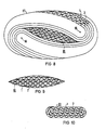
- Irregular cross-sectional shapes, but in particular also oval cross-sectional shapes, which have a more favorable stability behavior at a relatively high internal pressure, can, however, be produced according to the invention if filler pieces are used which fill the excess cross-sectional area and which in turn can be wound or layered from structured sheets.
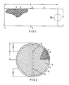
- a quasi-round-conical (or barrel-shaped, or hemispherical) end face shape can also be achieved with the honeycomb bodies according to the invention.
- a shape of the end faces is more favorable than a flat end face for some applications.
- Claim 12 describes the production of a honeycomb body with a round cross section
- claim 13 specifies the modified production for elongated cross sections
- Claim 14 additionally specifies a method for producing honeycomb bodies with an oval or irregular cross-sectional area. Except for the insertion of suitably shaped filler pieces in the sheet metal stack serving as the starting material, the method does not differ from those already described. In principle, it would also be possible to carry out the filler pieces by means of a suitable insertion device after the sheet stack has been devoured in opposite directions.
- honeycomb body with a round cross section is produced, as described in features a, b and c of claim 12.
- the ends of the structured metal sheets can then be fastened by joining technology and / or in a form-fitting manner only approximately in the middle of the jacket tube in the circumferential direction, preferably by a weld seam running in the circumferential direction around the jacket tube, if the friction forces which are present in any case are insufficient for the following steps.
- the central region of the honeycomb body thus formed is then pressed out to one end side using a stamp or the like.
- the individual sheets may rotate about the only fastening seam in their center, but do not tear away, so that considerable forces can be used for the deformation.
- both ends of each sheet metal layer touch the jacket tube, which makes it possible to connect each sheet metal layer to the jacket tube on both sides.
- the sheet metal layers no longer necessarily have to be connected to one another as a result of their opposing interweaving, however, they can hardly be moved out of position if they are firmly connected over the entire length or at several points of their jacket contact line.
- a technical connection of the ends only with the casing tube brings further advantages in manufacture according to claim 16. For example, only the inside of the casing tube needs to be provided with solder, e.g. B.
- honeycomb structures are generally very difficult to heat up, the jacket tube alone can be brought to the soldering temperature much more easily, for example by means of induction coils or external heat radiation. Apart from the greater elasticity of the honeycomb body according to the invention, this is a further essential advantage for the production.
- Figure 1 shows a stack of alternating layers of smooth 1 and corrugated 2 sheets stacked with the height h and length L.
- the stack does not necessarily have to be layered into a cuboid with flat side faces 4 at the beginning of the production process be.
- Other forms, e.g. B. parallelogram or the like may be more advantageous in the manufacture.
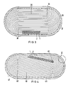
- Such a stack 3 is gripped at the fixed points 5, 6 by means of a fork or similarly acting device and devoured in opposite directions by turning the fork or bending the stack ends. In this way, a shape is created as shown schematically in FIG.
- the casing tube can also consist of several segments, for example.
- the individual sheets 1, 2 can be soldered to one another on the end face, preferably in an annular edge zone region 8. In this way, a stable structure is created even if individual layers should not touch the casing tube due to length deviations.
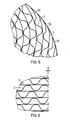
- FIG. 3 shows a correspondingly produced catalyst carrier body with an elongated cross-sectional area, which can be produced from a correspondingly longer stack of sheets 1, 2. Only the fixed points 35, 36 have to be selected offset from one another, which directly results in the desired cross-sectional shape, which fits into a corresponding jacket tube 37. Again, the end faces can be soldered in whole or in part, in particular in the edge zone area 38.
- FIG. 4 Another arrangement of the sheet metal layers 1, 2 in an elongated cross section, which is even more favorable under elasticity and stability considerations, is shown in FIG.
- This arrangement too, can be produced analogously to the previously described methods from a stack of metal sheets by engaging fixed points 45, 46 offset from one another.
- the stack may also have an approximately parallelogram-shaped cross section.
- the individual layers only need to be connected by their ends to the tubular casing 47.
- frontal soldering in particular in the edge zone area 48, is possible.
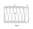
- the corrugated sheets 2 have straight sections 52 at their ends, which run approximately in the middle between the adjacent smooth sheets 1. With this configuration, the ends of all the sheets have the same scope for contact with the jacket tube, so that they nestle against it and a firm connection to the jacket tube can be accomplished more easily at different contact angles.
- FIG. 6 shows section VI from the edge area of FIG. 1.
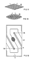
- FIG. 7 shows an alternative structure for the sheet metal layers of the catalyst carrier body according to the invention. Then both sheet metal layers 71, 72 can have corrugations which form a small angle ⁇ with one another.
- This embodiment has the advantage that no smooth sheet metal layers are required as intermediate layers and that in addition the channels formed by the corrugations intersect and communicate with one another, which leads to swirling of the gases and thus better contacting of the surfaces.
- FIG. 8 shows a further exemplary embodiment of the invention, which makes it clear that oval or more complicated cross sections can also be filled with sheet metal layers using the method according to the invention.
- the catalyst carrier body basically consists of a stack of smooth 1 and corrugated 2 which are intertwined in opposite directions Sheets. The entangling takes place analogously to the exemplary embodiment shown in FIG. 4 around the fixed points 85, 86.
- a filler 81 is additionally required, which is inserted into the stack before or after the entanglement.
- Such a filler 81 must be preformed in accordance with the cross-sectional area still to be filled, and in turn can in turn consist of structured metal sheets. In this way, almost any cross section can be filled within a casing tube 87.
- FIGS. 9, 10, 11 and 12 Suitable filler pieces are shown in FIGS. 9, 10, 11 and 12.
- the filler 81 shown in FIG. 9 consists of layered, different lengths of smooth 1 and corrugated 2 sheet metal strips.
- the filler is made of smooth 1 and corrugated 2 sheet metal strips which are spirally wound one above the other.
- FIGS. 11 and 12 show further variants suitable as filler pieces.
- FIG. 13 shows an example of the multitude of cross sections that can be filled in accordance with the present invention, an end view of a honeycomb body that is rectangular in cross section.
- the fixed points 135, 136 are in turn offset from the stack and have the same distance h on both their narrow sides and on both long sides. To produce such a cross section, however, several deformation steps of the sheet stack are necessary before insertion into the casing tube 137.
- Catalyst carrier bodies constructed according to the invention are insensitive to thermal alternating loads and can therefore be used in the vicinity of the engine with an extended service life.
Landscapes
- Chemical & Material Sciences (AREA)
- Engineering & Computer Science (AREA)
- Chemical Kinetics & Catalysis (AREA)
- Combustion & Propulsion (AREA)
- Mechanical Engineering (AREA)
- General Engineering & Computer Science (AREA)
- Health & Medical Sciences (AREA)
- Toxicology (AREA)
- Materials Engineering (AREA)
- Organic Chemistry (AREA)
- Catalysts (AREA)
- Exhaust Gas After Treatment (AREA)
Priority Applications (1)
| Application Number | Priority Date | Filing Date | Title |
|---|---|---|---|
| AT87106405T ATE45781T1 (de) | 1986-05-12 | 1987-05-04 | Wabenkoerper, insbesondere katalysatortr|gerk¯rper, mit gegensinnig verschlungenen metallblechschichten und verfahren zu seiner herstellung. |
Applications Claiming Priority (2)
| Application Number | Priority Date | Filing Date | Title |
|---|---|---|---|
| DE3615902 | 1986-05-12 | ||
| DE3615902 | 1986-05-12 |
Publications (2)
| Publication Number | Publication Date |
|---|---|
| EP0245737A1 true EP0245737A1 (fr) | 1987-11-19 |
| EP0245737B1 EP0245737B1 (fr) | 1989-08-23 |
Family
ID=6300625
Family Applications (1)
| Application Number | Title | Priority Date | Filing Date |
|---|---|---|---|
| EP87106405A Expired EP0245737B1 (fr) | 1986-05-12 | 1987-05-04 | Corps en forme de nid d'abeilles, en particulier support pour catalyseur, avec des tôles métalliques superposées, repliées en boucles de sens contraire, et son procédé de fabrication |
Country Status (10)
| Country | Link |
|---|---|
| US (2) | US4832998A (fr) |
| EP (1) | EP0245737B1 (fr) |
| JP (1) | JPS62273051A (fr) |
| KR (1) | KR950013327B1 (fr) |
| AT (1) | ATE45781T1 (fr) |
| BR (1) | BR8702369A (fr) |
| CA (1) | CA1270204A (fr) |
| DE (1) | DE3760479D1 (fr) |
| ES (1) | ES2010201B3 (fr) |
| GR (2) | GR880300176T1 (fr) |
Cited By (27)
| Publication number | Priority date | Publication date | Assignee | Title |
|---|---|---|---|---|
| DE3818512A1 (de) * | 1988-05-31 | 1989-12-07 | Interatom | Verfahren zum beleimen und beloten eines metallischen katalysator-traegerkoerpers und zugehoerige vorrichtung |
| DE4112354A1 (de) * | 1991-04-16 | 1992-10-22 | Behr Gmbh & Co | Vorrichtung zum katalytischen entgiften von abgasen |
| DE4233404A1 (de) * | 1992-10-05 | 1994-04-07 | Degussa | Metallträgerkatalysator mit in einem Mantelrohr eingeschweißter Matrix aus katalytisch beschichteten Metallbändern |
| US5328774A (en) * | 1990-08-06 | 1994-07-12 | Emitec Gesellschaft Fur Emissionstechnologie Mbh | Monolithic metal honeycomb body with varying number of channels |
| US5355671A (en) * | 1990-10-15 | 1994-10-18 | Emitec Gesellschaft Fur Emmissionstechnologie mbH | Method and apparatus for monitoring the function of a catalytic converter |
| DE4409026A1 (de) * | 1994-03-16 | 1995-11-09 | Bayerische Motoren Werke Ag | Abgaskatalysator, insbesondere für Brennkraftmaschinen |
| DE19514986A1 (de) * | 1995-04-24 | 1996-10-31 | Audi Ag | Katalysator |
| DE19521685A1 (de) * | 1995-06-14 | 1996-12-19 | Emitec Emissionstechnologie | Vorrichtung und Verfahren zum Herstellen eines Wabenkörpers |
| CN1035894C (zh) * | 1992-05-14 | 1997-09-17 | 埃米特放射技术股份有限公司 | 废气的催化清洁装置 |
| WO1999061151A1 (fr) * | 1998-05-26 | 1999-12-02 | Emitec Gesellschaft Für Emissionstechnologie Mbh | Corps en nids d'abeilles metallique monolithique avec un nombre de canaux variable |
| EP0919280A3 (fr) * | 1997-09-05 | 2000-01-19 | Kemira Metalkat Oy | Structure alvéolaire pour un catalyseur |
| US6109386A (en) * | 1998-02-03 | 2000-08-29 | Emitec Gesellschaft Fuer Emissionstechnologie Mbh | Honeycomb body with a flattened cross-sectional region and a method for producing the honeycomb body |
| WO2000068550A1 (fr) * | 1999-05-10 | 2000-11-16 | Emitec Gesellschaft Für Emissionstechnologie Mbh | Dispositif a structure en nid d'abeille comprenant differentes parties dans un tube de protection |
| WO2001019561A1 (fr) * | 1999-09-14 | 2001-03-22 | Emitec Gesellschaft Für Emissionstechnologie Mbh | Procede et dispositif d'une liaison d'assemblage frontale d'une matrice support d'un corps a nid d'abeilles |
| WO2003087549A1 (fr) * | 2002-04-18 | 2003-10-23 | Emitec Gesellschaft Für Emissionstechnologie Mbh | Corps support catalyseur calibre et dote d'une enveloppe ondulee et son procede de production |
| WO2003087548A1 (fr) | 2002-04-18 | 2003-10-23 | Emitec Gesellschaft Für Emissionstechnologie Mbh | Corps support de catalyseur comportant une gaine ondulee et procede de fabrication |
| WO2004063541A1 (fr) * | 2003-01-09 | 2004-07-29 | Emitec Gesellschaft Für Emissionstechnologie Mbh | Procede pour traiter un fluide et corps alveolaire |
| WO2005033484A1 (fr) * | 2003-10-02 | 2005-04-14 | Emitec Gesellschaft Für Emissionstechnologie Mbh | Procede de production d'un corps en nid d'abeilles metallique presentant une difference de longueur de couches |
| US7011893B2 (en) | 2002-08-02 | 2006-03-14 | Emitec Gesellschaft Fuer Emissionstechnologie Mbh | Metallic layer with regions of varying material thickness, method for producing such a metallic layer and honeycomb body at least partly produced from such metallic layers |
| US7197822B2 (en) | 2003-06-27 | 2007-04-03 | Emitec Gesellschaft Für Emissionstechnologie Mbh | Metallic honeycomb structure and process for producing the same |
| US7404254B2 (en) | 2002-04-18 | 2008-07-29 | Emitec Gesellschaft Fuer Emissions Technologie Mbh | Calibrated catalyst carrier body with corrugated casing and method for manufacturing the same |
| DE102007010759A1 (de) | 2007-03-06 | 2008-09-11 | Emitec Gesellschaft Für Emissionstechnologie Mbh | Verfahren zur Herstellung eines Wabenkörpers und entsprechender Wabenkörper |
| US7476366B2 (en) | 2002-04-18 | 2009-01-13 | Emitec Gesellschaft Fuer Emissionstechnologie Mbh | Catalyst carrier body with corrugated casing and process for producing the same |
| DE102009035612A1 (de) | 2009-07-31 | 2011-02-03 | Emitec Gesellschaft Für Emissionstechnologie Mbh | Wabenkörper und Verfahren zu seiner Herstellung |
| DE102016125641A1 (de) | 2016-12-23 | 2018-06-28 | Karlsruher Institut Für Technologie (Kit) | Verfahren zur Herstellung eines Erdgasubstitus aus wasserstoffhaltigen Gasmischungen |
| DE102016125640A1 (de) | 2016-12-23 | 2018-06-28 | Karlsruher Institut Für Technologie (Kit) | Verfahren zur Herstellung eines metallischen Formkörpers |
| US11192058B2 (en) | 2016-05-25 | 2021-12-07 | Vitesco Technologies GmbH | Honeycomb body for exhaust gas aftertreatment |
Families Citing this family (107)
| Publication number | Priority date | Publication date | Assignee | Title |
|---|---|---|---|---|
| ATE52836T1 (de) * | 1987-01-15 | 1990-06-15 | Emitec Emissionstechnologie | Metallischer katalysator-traegerkoerper mit verkuerztem mantelrohr. |
| DE8801788U1 (fr) * | 1988-02-11 | 1989-06-15 | Emitec Emissionstechnologie | |
| DE3809105A1 (de) * | 1988-03-18 | 1989-09-28 | Eberspaecher J | Vorrichtung zur katalytischen reinigung der abgase einer brennkraftmachine und verfahren zu deren herstellung |
| DE8816514U1 (fr) * | 1988-04-25 | 1989-10-26 | Emitec Emissionstechnologie | |
| DE8810816U1 (fr) * | 1988-08-26 | 1989-12-21 | Emitec Emissionstechnologie | |
| US5135794A (en) * | 1988-09-22 | 1992-08-04 | Emitec Gesellschaft Fur Emissionstechnologie Mbh | Honeycomb body, in particular catalyst carrier body, formed of a plurality of entwined bundles of sheet metal |
| BR8907458A (pt) * | 1988-09-22 | 1991-04-02 | Emitec Emissionstechnologie | Corpo alveolar,especialmente corpo de suporte de catalisador,constituido de uma multiplicidade de pilhas de chapa entrelacadas |
| US5403558A (en) * | 1988-10-04 | 1995-04-04 | Nippon Steel Corporation | Heat and fatigue resistant metallic carrier for automobile exhaust gas-purifying catalyst |
| JPH0545298B1 (fr) * | 1988-10-04 | 1993-07-08 | Shinnippon Seitetsu Kk | |
| US5190732A (en) * | 1988-10-11 | 1993-03-02 | Emitec Gesellschaft Fur Emissionstechnologie Mbh | Catalyst with a double casing system |
| DE8812762U1 (fr) * | 1988-10-11 | 1989-06-29 | Emitec Emissionstechnologie | |
| JPH0541782Y2 (fr) * | 1989-04-10 | 1993-10-21 | ||
| IT1232749B (it) * | 1989-04-12 | 1992-03-05 | I R T I Istituto Di Ricerca E | Depuratore di gas di scarico ad attivita`catalitica e silenziatore per motori a combustione interna |
| JPH0823409B2 (ja) * | 1989-06-20 | 1996-03-06 | エミテツク ゲゼルシヤフト フユア エミツシオンス テクノロギー ミツト ベシユレンクテル ハフツング | ガス流中の燃料の無炎燃焼による熱発生方法と装置 |
| JP2890503B2 (ja) * | 1989-07-26 | 1999-05-17 | 株式会社日本自動車部品総合研究所 | 多孔性担体 |
| DE8909128U1 (fr) * | 1989-07-27 | 1990-11-29 | Emitec Emissionstechnologie | |
| ES2050049T3 (es) * | 1989-12-22 | 1994-05-01 | Emitec Emissionstechnologie | Conducto de gas de escape con cuerpo soporte de catalizador atacado por el flujo en forma de helice. |
| FR2656376B1 (fr) * | 1989-12-22 | 1994-04-29 | Rosi Ets | Pot d'echappement, notamment catalytique, pour les gaz brules de moteurs a combustion interne. |
| DE59109132D1 (de) * | 1990-03-19 | 1999-07-08 | Emitec Emissionstechnologie | Verfahren und vorrichtung zur steuerung eines verbrennungsmotors unter einbeziehung der aktuellen temperatur eines nachgeschalteten katalysators |
| DE59100958D1 (de) * | 1990-03-19 | 1994-03-10 | Emitec Emissionstechnologie | Verfahren und vorrichtung zur betriebsüberwachung eines katalysators einer verbrennungsmaschine. |
| DE4016276C1 (fr) * | 1990-05-21 | 1991-06-20 | Behr Gmbh & Co | |
| DE59100916D1 (de) * | 1990-07-30 | 1994-03-03 | Emitec Emissionstechnologie | Elektrisch beheizbarer wabenkörper, insbesondere katalysator-trägerkörper, mit inneren tragstrukturen. |
| DE4025434A1 (de) * | 1990-08-10 | 1992-02-13 | Emitec Emissionstechnologie | Wabenkoerper mit querschnittsbereichen unterschiedlicher kanalgroessen, insbesondere katalysator-traegerkoerper |
| DE4027207A1 (de) * | 1990-08-28 | 1992-03-05 | Emitec Emissionstechnologie | Ueberwachung der katalytischen aktivitaet eines katalysators im abgassystem einer brennkraftmaschine |
| JPH0815559B2 (ja) * | 1990-11-13 | 1996-02-21 | 新日本製鐵株式会社 | 耐熱応力・耐熱疲労特性の優れたレーストラック型自動車排ガス触媒用金属担体 |
| DE4038829A1 (de) * | 1990-12-05 | 1992-06-11 | Emitec Emissionstechnologie | Ermittlung einer reaktionszone in einem katalysator |
| KR0140505B1 (ko) * | 1991-01-31 | 1998-06-01 | 볼프강 마우스, 지그프리트 나스 | 불균일하게 전기 가열되는 벌집형 본체 |
| US5525309A (en) * | 1991-01-31 | 1996-06-11 | Emitec Gesellschaft Fuer Emissionstechnologie Mbh | Honeycomb body with a plurality of disks braced against one another |
| DE4111712A1 (de) * | 1991-04-10 | 1992-10-22 | Emitec Emissionstechnologie | Elektrisch leitfaehiger wabenkoerper |
| US5240682A (en) * | 1991-05-06 | 1993-08-31 | W. R. Grace & Co.-Conn | Reinforced corrugated thin metal foil strip useful in a catalytic converter core, a catalytic converter core containing said strip and an electrically heatable catalytic converter containing said core |
| JP2509478B2 (ja) * | 1991-05-09 | 1996-06-19 | 昭和飛行機工業株式会社 | ハニカム構造体およびその製造方法 |
| DE4142533A1 (de) * | 1991-12-21 | 1993-06-24 | Emitec Emissionstechnologie | Verfahren zum verloeten von traegerkoerpern von abgaskatalysatoren |
| CA2083742A1 (fr) * | 1992-02-19 | 1993-08-20 | David T. Sheller | Element central pour convertisseur catalytique |
| DE59300601D1 (de) * | 1992-04-03 | 1995-10-19 | Emitec Emissionstechnologie | Konischer wabenkörper. |
| JPH0639294A (ja) * | 1992-05-04 | 1994-02-15 | W R Grace & Co | 触媒式コンバーターのためのコア要素 |
| US5272876A (en) * | 1992-05-20 | 1993-12-28 | W. R. Grace & Co.-Conn. | Core element for catalytic converter |
| JP2711938B2 (ja) * | 1992-07-14 | 1998-02-10 | エミテク・ゲゼルシャフト・フュール・エミシオーンテクノロギー・ミット・ベシュレンクテル・ハフツング | 絡み合せられたメタルシートの層を持つ金属のハニカム状の本体およびその製造方法 |
| JP3224609B2 (ja) * | 1992-09-29 | 2001-11-05 | 新日本製鐵株式会社 | 排ガス浄化触媒用メタル担体 |
| US5308591A (en) * | 1992-11-09 | 1994-05-03 | W. R. Grace & Co.-Conn. | Core body for catalytic converter |
| DE4241469A1 (de) * | 1992-12-09 | 1994-06-16 | Emitec Emissionstechnologie | Katalytischer Konverter mit zwei oder mehr Wabenkörpern in einem Mantelrohr und Verfahren zu seiner Herstellung |
| JP3392895B2 (ja) * | 1993-01-08 | 2003-03-31 | 臼井国際産業株式会社 | X−ラップタイプのメタルハニカム体 |
| US5866230A (en) * | 1993-01-11 | 1999-02-02 | Emitec Gesellschaft Fuer Emissionstechnologie Gmbh | Extruded honeycomb body of ceramic and/or metallic material with increased flexibility |
| DE4303950C1 (de) * | 1993-02-10 | 1994-10-06 | Emitec Emissionstechnologie | In einem inneren und einem äußeren Mantelrohr gehalterter metallischer Wabenkörper, insbesondere Katalysator-Trägerkörper |
| JPH06246167A (ja) * | 1993-02-23 | 1994-09-06 | Usui Internatl Ind Co Ltd | ハニカム体 |
| DE4310933C2 (de) * | 1993-04-02 | 1999-01-07 | Bayerische Motoren Werke Ag | Abgaskatalysator, insbesondere für Brennkraftmaschinen |
| DE4411302C1 (de) * | 1994-03-31 | 1995-10-19 | Degussa | Verfahren zur Herstellung eines beschichteten, monolithischen Trägerkatalysators |
| DE19525262A1 (de) * | 1994-07-11 | 1996-02-15 | Usui Kokusai Sangyo K K Ltd | Metallsubstrat für Abgasreinigungskatalysator |
| JPH0824670A (ja) * | 1994-07-11 | 1996-01-30 | Usui Internatl Ind Co Ltd | 排気ガス浄化用メタルハニカム体 |
| US6045628A (en) * | 1996-04-30 | 2000-04-04 | American Scientific Materials Technologies, L.P. | Thin-walled monolithic metal oxide structures made from metals, and methods for manufacturing such structures |
| US5814164A (en) | 1994-11-09 | 1998-09-29 | American Scientific Materials Technologies L.P. | Thin-walled, monolithic iron oxide structures made from steels, and methods for manufacturing such structures |
| US5657923A (en) * | 1995-02-01 | 1997-08-19 | W. R. Grace & Co.-Conn. | Brazing of catalyzed converter bodies |
| DE19507299A1 (de) * | 1995-03-02 | 1996-09-05 | Emitec Emissionstechnologie | Wabenkörper mit nur teilweiser Anbindung an ein Mantelrohr |
| JP3755008B2 (ja) * | 1995-05-22 | 2006-03-15 | 株式会社日本自動車部品総合研究所 | 排ガス浄化用金属製触媒担体の製造方法 |
| US6029488A (en) * | 1995-06-20 | 2000-02-29 | Emitec Gesellschaft Fuer Emissionstechnologie Mbh | Apparatus and process for producing a honeycomb body from intertwined sheet metal layers |
| DE19522327A1 (de) * | 1995-06-20 | 1997-01-02 | Emitec Emissionstechnologie | Vorrichtung und Verfahren zum Herstellen eines Wabenkörpers aus verschlungenen Blechlagen |
| US5846495A (en) * | 1995-07-12 | 1998-12-08 | Engelhard Corporation | Structure for converter body |
| DE19530850A1 (de) | 1995-08-22 | 1997-02-27 | Emitec Emissionstechnologie | Verfahren zum Herstellen eines Wabenkörpers aus zumindest zum Teil schichtartig aufgebauten Metallblechlagen |
| WO1997023325A1 (fr) * | 1995-12-22 | 1997-07-03 | W.R. Grace & Co. | Assemblage et procede pour fabriquer des structures de pot catalytique |
| WO1997023273A1 (fr) * | 1995-12-22 | 1997-07-03 | W.R. Grace & Co.-Conn. | Ensemble et procede de fabrication de structures de convertisseurs catalytiques |
| US6060173A (en) * | 1996-04-17 | 2000-05-09 | Englehard Corporation | Metal honeycomb body |
| US6602477B2 (en) | 1996-08-05 | 2003-08-05 | Usui Kokusai Sangyo Kaisha, Ltd. | Metal honeycomb structure |
| US5735158A (en) * | 1996-10-10 | 1998-04-07 | Engelhard Corporation | Method and apparatus for skew corrugating foil |
| DE19643934A1 (de) | 1996-10-30 | 1998-05-07 | Emitec Emissionstechnologie | Verfahren und Vorrichtung zum Herstellen strukturierter Metallbleche |
| DE19704521A1 (de) | 1997-02-06 | 1998-08-13 | Emitec Emissionstechnologie | Verfahren und Vorrichtung zur Herstellung eines Wabenkörpers |
| GB2325424B (en) * | 1997-05-20 | 2001-01-24 | Emitec Emissionstechnologie | Production of a honeycomb body of twisted sheet layers |
| DE19805563A1 (de) | 1998-02-11 | 1999-08-19 | Emitec Emissionstechnologie | Verfahren zum Herstellen eines Wabenkörpers mittels eines Hartblechs |
| DE19825018A1 (de) | 1998-06-04 | 1999-12-09 | Emitec Emissionstechnologie | Verfahren und Blechpaket zur Herstellung eines Wabenkörpers mit einer Vielzahl von für ein Fluid durchlässigen Kanälen |
| DE19844075A1 (de) * | 1998-09-25 | 2000-03-30 | Man Nutzfahrzeuge Ag | Kompakter Kreuzkanalmischer |
| US6461562B1 (en) | 1999-02-17 | 2002-10-08 | American Scientific Materials Technologies, Lp | Methods of making sintered metal oxide articles |
| DE19928237A1 (de) * | 1999-06-21 | 2000-12-28 | Emitec Emissionstechnologie | Einrichtung zur katalytischen Umsetzung mit einem bereichsweise an einen Mantel angebundenen Trägerkörper |
| DE10208871A1 (de) | 2001-03-16 | 2003-09-18 | Emitec Emissionstechnologie | Verfahren und Vorrichtung zur Herstellung eines Wabenkörpers sowie Wabenkörper |
| DE10117088B4 (de) * | 2001-04-06 | 2005-09-08 | Emitec Gesellschaft Für Emissionstechnologie Mbh | Verfahren und Vorrichtung zur Herstellung von metallischen Wabenkörpern mit Strahlungsheizern |
| DE10122082C1 (de) * | 2001-05-07 | 2002-11-14 | Emitec Emissionstechnologie | Blechfolie mit Gleitstruktur, Wabenkörper und Verfahren zu seiner Herstellung |
| DE10162161A1 (de) | 2001-12-17 | 2003-07-03 | Emitec Emissionstechnologie | Vorrichtung und Verfahren zur Schalldämpfung im Abgassystem einer Verbrennungskraftmaschine |
| DE10226282A1 (de) | 2002-06-13 | 2003-12-24 | Emitec Emissionstechnologie | Nicht-zylindrischer Katalysator-Trägerkörper sowie Werkzeug und Verfahren zu seiner Herstellung |
| DE10235767C1 (de) * | 2002-08-02 | 2003-12-04 | Emitec Emissionstechnologie | Blechlage mit Bereichen unterschiedlicher Materialdicke, Verfahren zur Herstellung einer solchen Blechlage und aus solchen Blechlagen hergestellter Wabenkörper |
| DE10237512C1 (de) * | 2002-08-16 | 2003-11-13 | Emitec Emissionstechnologie | Metallischer Wabenkörper aus zumindest teilweise gelochten Blechlagen |
| US7083860B2 (en) | 2002-08-16 | 2006-08-01 | Emitec Gesellschaft Fuer Emissionstechnologie Mbh | Metallic honeycomb body having at least partially perforated sheet-metal layers |
| DE10239205A1 (de) | 2002-08-21 | 2004-03-04 | Emitec Gesellschaft Für Emissionstechnologie Mbh | Verfahren und Vorrichtung zur Herstellung von Wabenkörpern und Wabenkörper |
| WO2004063540A1 (fr) | 2003-01-14 | 2004-07-29 | Emitec Gesellschaft Für Emissionstechnologie Mbh | Unite de retraitement des gaz d'echappement peu encombrante et pourvue de zones d'ecoulement aller-retour imbriquees avec une entree et une sortie de gaz du meme cote |
| DE10311235A1 (de) | 2003-03-14 | 2004-10-14 | Emitec Gesellschaft Für Emissionstechnologie Mbh | Mehrsträngiges Abgassystem mit mindestens einem Messfühler, Wabenkörper mit einer Ausnehmung für mindestens einen Messfühler und Verfahren zum Betrieb eines mehrsträngigen Abgassystems |
| DE10321105A1 (de) * | 2003-05-09 | 2004-12-02 | Emitec Gesellschaft Für Emissionstechnologie Mbh | Regeneration einer Partikelfalle |
| DE10329000A1 (de) | 2003-06-27 | 2005-01-27 | Emitec Gesellschaft Für Emissionstechnologie Mbh | Abgasnachbehandlungsanlage mit einem Gegenstromgehäuse, sowie entsprechendes Verfahren zur Abgasnachbehandlung |
| DE10337265A1 (de) | 2003-08-13 | 2005-03-10 | Emitec Emissionstechnologie | Rollnahtgeschweißter Körper zur Abgasbehandlung |
| DE10338360A1 (de) | 2003-08-21 | 2005-03-31 | Emitec Gesellschaft Für Emissionstechnologie Mbh | Verfahren und Vorrichtung zur Herstellung eines Wabenkörpers |
| DE10345896A1 (de) | 2003-09-30 | 2005-04-21 | Emitec Emissionstechnologie | Beschichteter Wabenkörper mit Messfühler |
| DE102004058268B4 (de) * | 2003-12-11 | 2016-05-19 | Continental Automotive Gmbh | Verstärktes Gehäuse einer Abgasreinigungskomponente |
| DE102004001418A1 (de) | 2004-01-09 | 2005-07-28 | Emitec Gesellschaft Für Emissionstechnologie Mbh | Fluid-Umformung von Metallblechen |
| DE102004021037A1 (de) * | 2004-04-29 | 2005-11-24 | Emitec Gesellschaft Für Emissionstechnologie Mbh | Verfahren zur Herstellung einer hochtemperaturfesten Struktur |
| DE102004021038A1 (de) | 2004-04-29 | 2005-11-24 | Emitec Gesellschaft Für Emissionstechnologie Mbh | Verfahren zur Herstellung einer hochtemperaturfesten Struktur |
| US7320778B2 (en) * | 2004-07-21 | 2008-01-22 | Catacel Corp. | High-performance catalyst support |
| DE102004058285A1 (de) * | 2004-12-02 | 2006-06-08 | Emitec Gesellschaft Für Emissionstechnologie Mbh | Verbindungsmaterial zum Positionieren von Lotmaterial, Verfahren zur Herstellung eines Wabenkörpers und entsprechender Wabenkörper |
| US7655194B2 (en) * | 2005-01-18 | 2010-02-02 | Dcl International Inc. | Catalyst substrate support |
| DE102005007403A1 (de) | 2005-02-18 | 2006-08-31 | Emitec Gesellschaft Für Emissionstechnologie Mbh | Wabenkörper mit internen Kavernen |
| DE102005009585A1 (de) | 2005-02-28 | 2006-08-31 | Emitec Gesellschaft Für Emissionstechnologie Mbh | Wabenkörper mit zerklüfteten Stirnseiten |
| DE102005028044A1 (de) * | 2005-06-17 | 2006-12-28 | Emitec Gesellschaft Für Emissionstechnologie Mbh | Herstellung von, insbesondere großen, Wabenkörpern für die mobile Abgasnachbehandlung |
| GB2427578B (en) * | 2005-06-24 | 2007-09-12 | Reef Resources Ltd | Handling foraminous sheets in industrial catalysis |
| US7501102B2 (en) * | 2005-07-28 | 2009-03-10 | Catacel Corp. | Reactor having improved heat transfer |
| DE102005038572A1 (de) * | 2005-08-12 | 2007-02-15 | Emitec Gesellschaft Für Emissionstechnologie Mbh | Vorrichtung und Verfahren zur Herstellung metallischer Wabenkörper mit mindestens einem Formsegment |
| DE102008016148A1 (de) * | 2008-03-28 | 2009-10-01 | Emitec Gesellschaft Für Emissionstechnologie Mbh | Wabenkörper und Verfahren zur Herstellung eines gelöteten Wabenkörpers |
| CN203321645U (zh) * | 2013-06-01 | 2013-12-04 | 黄小春 | 一种孔道交错型高性能金属蜂窝载体 |
| CN103628957A (zh) * | 2013-06-01 | 2014-03-12 | 黄小春 | 一种孔道交错型高性能金属蜂窝载体 |
| CN103670623B (zh) * | 2013-12-27 | 2016-08-17 | 吉林省众鑫汽车装备有限公司 | 汽车及金属纤维网载体 |
| US10479678B2 (en) * | 2014-05-15 | 2019-11-19 | Lawrence Livermore National Security, Llc | Ortho-H2 refueling for extended cryogenic pressure vessel dormancy |
| CN106469232A (zh) * | 2015-08-19 | 2017-03-01 | 南京理工大学 | 一种计算弯曲胞元蜂窝轴向压缩应力的方法 |
| RU2721686C1 (ru) * | 2016-09-23 | 2020-05-21 | Басф Корпорейшн | Каталитические субстраты |
| CN108994476B (zh) * | 2018-09-12 | 2021-09-03 | 上海电气核电设备有限公司 | 提高管子与封头相连接的j型坡口焊缝质量的焊接工艺 |
Citations (3)
| Publication number | Priority date | Publication date | Assignee | Title |
|---|---|---|---|---|
| DE2727967A1 (de) * | 1977-06-22 | 1979-01-18 | Audi Nsu Auto Union Ag | Monolithischer metallkatalysator zum entgiften der abgase von brennkraftmaschinen, insbesondere in kraftfahrzeugen, sowie verfahren zum herstellen desselben |
| GB2079174A (en) * | 1980-07-10 | 1982-01-20 | Gen Motors Corp | Wound foil catalytic converter structure and method for manufacturing same |
| DE3341868A1 (de) * | 1983-11-19 | 1985-05-30 | Süddeutsche Kühlerfabrik Julius Fr. Behr GmbH & Co KG, 7000 Stuttgart | Matrix fuer einen katalytischen reaktor |
Family Cites Families (12)
| Publication number | Priority date | Publication date | Assignee | Title |
|---|---|---|---|---|
| JPS548202B2 (fr) * | 1972-12-07 | 1979-04-13 | ||
| US3890108A (en) * | 1973-02-09 | 1975-06-17 | Hughes Aircraft Co | Structural panel bent from laminated honeycomb |
| US4014968A (en) * | 1974-07-19 | 1977-03-29 | Corning Glass Works | Shrinkage control of cellular ceramic bodies having axial cavities |
| US4042162A (en) * | 1975-07-11 | 1977-08-16 | General Motors Corporation | Airfoil fabrication |
| CA1102706A (fr) * | 1977-05-06 | 1981-06-09 | Rainer Scholz | Catalyseur homogene en metal pour eliminer les composants toxiques en presence dans les gaz d'echappement des moteurs a combustion interne |
| US4256172A (en) * | 1979-06-14 | 1981-03-17 | Ford Motor Company | Heat exchanger matrix configuration with high thermal shock resistance |
| US4245769A (en) * | 1979-06-28 | 1981-01-20 | General Motors Corporation | Laminate bonding method |
| DE2937209C2 (de) * | 1979-09-14 | 1984-06-07 | Kernforschungsanlage Jülich GmbH, 5170 Jülich | Spaltprodukt-Filter |
| DE3311654A1 (de) * | 1983-03-30 | 1984-10-04 | Interatom Internationale Atomreaktorbau Gmbh, 5060 Bergisch Gladbach | Katalysator-traegerkoerper fuer verbrennungskraftmaschinen mit dehnungsschlitzen |
| DE3312944A1 (de) * | 1983-04-11 | 1984-10-11 | Interatom Internationale Atomreaktorbau Gmbh, 5060 Bergisch Gladbach | Spannungsentlastetes metalltraegergehaeuse fuer abgaskatalysatoren mit hoher thermischer betriebsbelastung |
| US4598063A (en) * | 1985-08-09 | 1986-07-01 | Retallick William B | Spiral catalyst support and method of making it |
| US4708757A (en) * | 1986-07-21 | 1987-11-24 | Guthrie Walker L | Method of forming corrugated panel |
-
1987
- 1987-05-04 EP EP87106405A patent/EP0245737B1/fr not_active Expired
- 1987-05-04 ES ES87106405T patent/ES2010201B3/es not_active Expired
- 1987-05-04 AT AT87106405T patent/ATE45781T1/de active
- 1987-05-04 DE DE8787106405T patent/DE3760479D1/de not_active Expired
- 1987-05-08 JP JP62113748A patent/JPS62273051A/ja not_active Expired - Lifetime
- 1987-05-08 CA CA000536663A patent/CA1270204A/fr not_active Expired - Fee Related
- 1987-05-11 US US07/048,361 patent/US4832998A/en not_active Expired - Lifetime
- 1987-05-11 BR BR8702369A patent/BR8702369A/pt not_active IP Right Cessation
- 1987-05-12 KR KR87004622A patent/KR950013327B1/ko not_active IP Right Cessation
-
1989
- 1989-03-13 US US07/322,772 patent/US4923109A/en not_active Expired - Lifetime
- 1989-06-22 GR GR88300176T patent/GR880300176T1/el unknown
- 1989-08-24 GR GR89400153T patent/GR3000134T3/el unknown
Patent Citations (3)
| Publication number | Priority date | Publication date | Assignee | Title |
|---|---|---|---|---|
| DE2727967A1 (de) * | 1977-06-22 | 1979-01-18 | Audi Nsu Auto Union Ag | Monolithischer metallkatalysator zum entgiften der abgase von brennkraftmaschinen, insbesondere in kraftfahrzeugen, sowie verfahren zum herstellen desselben |
| GB2079174A (en) * | 1980-07-10 | 1982-01-20 | Gen Motors Corp | Wound foil catalytic converter structure and method for manufacturing same |
| DE3341868A1 (de) * | 1983-11-19 | 1985-05-30 | Süddeutsche Kühlerfabrik Julius Fr. Behr GmbH & Co KG, 7000 Stuttgart | Matrix fuer einen katalytischen reaktor |
Cited By (33)
| Publication number | Priority date | Publication date | Assignee | Title |
|---|---|---|---|---|
| DE3818512A1 (de) * | 1988-05-31 | 1989-12-07 | Interatom | Verfahren zum beleimen und beloten eines metallischen katalysator-traegerkoerpers und zugehoerige vorrichtung |
| US5328774A (en) * | 1990-08-06 | 1994-07-12 | Emitec Gesellschaft Fur Emissionstechnologie Mbh | Monolithic metal honeycomb body with varying number of channels |
| US5355671A (en) * | 1990-10-15 | 1994-10-18 | Emitec Gesellschaft Fur Emmissionstechnologie mbH | Method and apparatus for monitoring the function of a catalytic converter |
| DE4112354A1 (de) * | 1991-04-16 | 1992-10-22 | Behr Gmbh & Co | Vorrichtung zum katalytischen entgiften von abgasen |
| CN1035894C (zh) * | 1992-05-14 | 1997-09-17 | 埃米特放射技术股份有限公司 | 废气的催化清洁装置 |
| DE4233404A1 (de) * | 1992-10-05 | 1994-04-07 | Degussa | Metallträgerkatalysator mit in einem Mantelrohr eingeschweißter Matrix aus katalytisch beschichteten Metallbändern |
| DE4409026A1 (de) * | 1994-03-16 | 1995-11-09 | Bayerische Motoren Werke Ag | Abgaskatalysator, insbesondere für Brennkraftmaschinen |
| DE19514986A1 (de) * | 1995-04-24 | 1996-10-31 | Audi Ag | Katalysator |
| DE19521685A1 (de) * | 1995-06-14 | 1996-12-19 | Emitec Emissionstechnologie | Vorrichtung und Verfahren zum Herstellen eines Wabenkörpers |
| DE19521685C2 (de) * | 1995-06-14 | 1998-04-16 | Emitec Emissionstechnologie | Verfahren und Vorrichtung zum Herstellen eines Wabenkörpers |
| EP0919280A3 (fr) * | 1997-09-05 | 2000-01-19 | Kemira Metalkat Oy | Structure alvéolaire pour un catalyseur |
| US6109386A (en) * | 1998-02-03 | 2000-08-29 | Emitec Gesellschaft Fuer Emissionstechnologie Mbh | Honeycomb body with a flattened cross-sectional region and a method for producing the honeycomb body |
| WO1999061151A1 (fr) * | 1998-05-26 | 1999-12-02 | Emitec Gesellschaft Für Emissionstechnologie Mbh | Corps en nids d'abeilles metallique monolithique avec un nombre de canaux variable |
| WO2000068550A1 (fr) * | 1999-05-10 | 2000-11-16 | Emitec Gesellschaft Für Emissionstechnologie Mbh | Dispositif a structure en nid d'abeille comprenant differentes parties dans un tube de protection |
| WO2001019561A1 (fr) * | 1999-09-14 | 2001-03-22 | Emitec Gesellschaft Für Emissionstechnologie Mbh | Procede et dispositif d'une liaison d'assemblage frontale d'une matrice support d'un corps a nid d'abeilles |
| WO2003087548A1 (fr) | 2002-04-18 | 2003-10-23 | Emitec Gesellschaft Für Emissionstechnologie Mbh | Corps support de catalyseur comportant une gaine ondulee et procede de fabrication |
| WO2003087549A1 (fr) * | 2002-04-18 | 2003-10-23 | Emitec Gesellschaft Für Emissionstechnologie Mbh | Corps support catalyseur calibre et dote d'une enveloppe ondulee et son procede de production |
| US7943096B2 (en) | 2002-04-18 | 2011-05-17 | Emitec Gesellschaft Fuer Emissionstechnologie Mbh | Calibrated catalyst carrier body with corrugated casing |
| KR100913877B1 (ko) * | 2002-04-18 | 2009-08-26 | 에미텍 게젤샤프트 퓌어 에미시온스테크놀로기 엠베하 | 주름형 케이스를 갖춘 규격화된 촉매 지지 부재 및 그것의제조 방법 |
| US7476366B2 (en) | 2002-04-18 | 2009-01-13 | Emitec Gesellschaft Fuer Emissionstechnologie Mbh | Catalyst carrier body with corrugated casing and process for producing the same |
| CN100356043C (zh) * | 2002-04-18 | 2007-12-19 | 排放技术有限公司 | 具有波纹外壳的经过调校的催化剂基体及其制造方法 |
| US7404254B2 (en) | 2002-04-18 | 2008-07-29 | Emitec Gesellschaft Fuer Emissions Technologie Mbh | Calibrated catalyst carrier body with corrugated casing and method for manufacturing the same |
| US7011893B2 (en) | 2002-08-02 | 2006-03-14 | Emitec Gesellschaft Fuer Emissionstechnologie Mbh | Metallic layer with regions of varying material thickness, method for producing such a metallic layer and honeycomb body at least partly produced from such metallic layers |
| US7448201B2 (en) | 2003-01-09 | 2008-11-11 | Emitec Gesellschaft Fuer Emissionstechnologie Mbh | Honeycomb body and method for treating a fluid |
| WO2004063541A1 (fr) * | 2003-01-09 | 2004-07-29 | Emitec Gesellschaft Für Emissionstechnologie Mbh | Procede pour traiter un fluide et corps alveolaire |
| US7197822B2 (en) | 2003-06-27 | 2007-04-03 | Emitec Gesellschaft Für Emissionstechnologie Mbh | Metallic honeycomb structure and process for producing the same |
| WO2005033484A1 (fr) * | 2003-10-02 | 2005-04-14 | Emitec Gesellschaft Für Emissionstechnologie Mbh | Procede de production d'un corps en nid d'abeilles metallique presentant une difference de longueur de couches |
| DE102007010759A1 (de) | 2007-03-06 | 2008-09-11 | Emitec Gesellschaft Für Emissionstechnologie Mbh | Verfahren zur Herstellung eines Wabenkörpers und entsprechender Wabenkörper |
| DE102009035612A1 (de) | 2009-07-31 | 2011-02-03 | Emitec Gesellschaft Für Emissionstechnologie Mbh | Wabenkörper und Verfahren zu seiner Herstellung |
| US11192058B2 (en) | 2016-05-25 | 2021-12-07 | Vitesco Technologies GmbH | Honeycomb body for exhaust gas aftertreatment |
| DE102016125641A1 (de) | 2016-12-23 | 2018-06-28 | Karlsruher Institut Für Technologie (Kit) | Verfahren zur Herstellung eines Erdgasubstitus aus wasserstoffhaltigen Gasmischungen |
| DE102016125640A1 (de) | 2016-12-23 | 2018-06-28 | Karlsruher Institut Für Technologie (Kit) | Verfahren zur Herstellung eines metallischen Formkörpers |
| DE102016125641B4 (de) | 2016-12-23 | 2022-08-25 | Karlsruher Institut Für Technologie (Kit) | Reaktor und Verfahren zur Herstellung eines Erdgasubstitus aus wasserstoffhaltigen Gasmischungen |
Also Published As
| Publication number | Publication date |
|---|---|
| US4832998A (en) | 1989-05-23 |
| KR870011350A (ko) | 1987-12-22 |
| JPS62273051A (ja) | 1987-11-27 |
| JPH0464740B1 (fr) | 1992-10-15 |
| DE3760479D1 (en) | 1989-09-28 |
| ATE45781T1 (de) | 1989-09-15 |
| KR950013327B1 (en) | 1995-11-02 |
| EP0245737B1 (fr) | 1989-08-23 |
| US4923109A (en) | 1990-05-08 |
| BR8702369A (pt) | 1988-02-17 |
| GR3000134T3 (en) | 1990-11-29 |
| CA1270204A (fr) | 1990-06-12 |
| ES2010201B3 (es) | 1989-11-01 |
| GR880300176T1 (en) | 1989-06-22 |
Similar Documents
| Publication | Publication Date | Title |
|---|---|---|
| EP0245737B1 (fr) | Corps en forme de nid d'abeilles, en particulier support pour catalyseur, avec des tôles métalliques superposées, repliées en boucles de sens contraire, et son procédé de fabrication | |
| EP0650552B1 (fr) | Corps metallique en nid d'abeilles compose de couches de tole entrelacees et son procede de fabrication | |
| EP0263324B1 (fr) | Support de catalyseur pour réacteur d'épuration de gaz d'échappement | |
| EP0436533B1 (fr) | Corps en nid d'abeille, ayant notamment des toles en s partiellement renforcees | |
| DE4016276C1 (fr) | ||
| DE2827188C2 (de) | Bohrlochsieb | |
| EP0245738A1 (fr) | Corps métallique en forme de nid d'abeilles, en particulier support pour catalyseur, avec paroi de support, et son procédé de fabrication | |
| WO1994013939A1 (fr) | Convertisseur catalytique a deux ou plusieurs corps en nid-d'abeilles contenus dans une enveloppe tubulaire, et son procede de fabrication | |
| DE3922264C2 (de) | Aus Metall hergestellter Trägerkörper für einen Abgasreinigungskatalysator und Verfahren zu seiner Herstellung | |
| DE3738537C2 (fr) | ||
| EP0542805B1 (fr) | Corps en nid d'abeilles ayant des canaux a sections transversales diverses, notamment corps de support de catalyseur | |
| DE3744265C2 (de) | Rußfilter zur Abgasreinigung in Kraftfahrzeugen | |
| EP1644620B1 (fr) | Procede de fabrication d'une structure en nid d'abeilles metallique | |
| EP0983425A1 (fr) | Corps alveolaire muni d'un systeme permettant d'eviter les vibrations mecaniques | |
| EP0332891B1 (fr) | Appareil pour purifier les gaz d'échappement des moteurs à combustion interne, ainsi que sa préparation | |
| EP0958053B1 (fr) | Procede et dispositif pour produire un corps alveole | |
| EP1525378B1 (fr) | Couche metallique a parties presentant des epaisseurs de materiau differentes, son procede de production et corps en nid d'abeille produits au moins partiellement a partir desdites couches metalliques | |
| DE19646242A1 (de) | Katalytischer Konverter für einen Kleinmotor | |
| DE4243079C2 (de) | Wabenkörper und Verfahren zu seiner Herstellung | |
| DE4219673A1 (de) | Metallträger aus Streckmetallband | |
| DE4129894A1 (de) | Elektrische isolierung von strukturen in einem wabenkoerper, insbesondere einem elektrisch beheizbaren katalysator-traegerkoerper | |
| DE4223134A1 (de) | Metallischer Wabenkörper aus verschlungenen Blechlagen und Verfahren zur seiner Herstellung | |
| EP0798526A2 (fr) | Corps de chauffe, en particulier radiateur | |
| DD283667A5 (de) | Verfahren zur herstellung und verstaerkung eines zur abgasreinigung dienenden katalysatorwabenkoerpers | |
| DE2534846C2 (de) | Verfahren zum Herstellen eines Nadelfräsers |
Legal Events
| Date | Code | Title | Description |
|---|---|---|---|
| PUAI | Public reference made under article 153(3) epc to a published international application that has entered the european phase |
Free format text: ORIGINAL CODE: 0009012 |
|
| AK | Designated contracting states |
Kind code of ref document: A1 Designated state(s): AT BE CH DE ES FR GB GR IT LI LU NL SE |
|
| 17P | Request for examination filed |
Effective date: 19871218 |
|
| 17Q | First examination report despatched |
Effective date: 19880429 |
|
| GRAA | (expected) grant |
Free format text: ORIGINAL CODE: 0009210 |
|
| AK | Designated contracting states |
Kind code of ref document: B1 Designated state(s): AT BE CH DE ES FR GB GR IT LI LU NL SE |
|
| REF | Corresponds to: |
Ref document number: 45781 Country of ref document: AT Date of ref document: 19890915 Kind code of ref document: T |
|
| REF | Corresponds to: |
Ref document number: 3760479 Country of ref document: DE Date of ref document: 19890928 |
|
| ET | Fr: translation filed | ||
| ITF | It: translation for a ep patent filed |
Owner name: STUDIO JAUMANN |
|
| GBT | Gb: translation of ep patent filed (gb section 77(6)(a)/1977) | ||
| REG | Reference to a national code |
Ref country code: GR Ref legal event code: FG4A Free format text: 3000134 |
|
| PLBE | No opposition filed within time limit |
Free format text: ORIGINAL CODE: 0009261 |
|
| STAA | Information on the status of an ep patent application or granted ep patent |
Free format text: STATUS: NO OPPOSITION FILED WITHIN TIME LIMIT |
|
| 26N | No opposition filed | ||
| ITTA | It: last paid annual fee | ||
| EPTA | Lu: last paid annual fee | ||
| EAL | Se: european patent in force in sweden |
Ref document number: 87106405.1 |
|
| PGFP | Annual fee paid to national office [announced via postgrant information from national office to epo] |
Ref country code: AT Payment date: 19980506 Year of fee payment: 12 |
|
| PGFP | Annual fee paid to national office [announced via postgrant information from national office to epo] |
Ref country code: GR Payment date: 19980513 Year of fee payment: 12 |
|
| PGFP | Annual fee paid to national office [announced via postgrant information from national office to epo] |
Ref country code: LU Payment date: 19980514 Year of fee payment: 12 Ref country code: BE Payment date: 19980514 Year of fee payment: 12 |
|
| PGFP | Annual fee paid to national office [announced via postgrant information from national office to epo] |
Ref country code: NL Payment date: 19980518 Year of fee payment: 12 |
|
| PGFP | Annual fee paid to national office [announced via postgrant information from national office to epo] |
Ref country code: CH Payment date: 19980810 Year of fee payment: 12 |
|
| PG25 | Lapsed in a contracting state [announced via postgrant information from national office to epo] |
Ref country code: LU Free format text: LAPSE BECAUSE OF NON-PAYMENT OF DUE FEES Effective date: 19990504 Ref country code: AT Free format text: LAPSE BECAUSE OF NON-PAYMENT OF DUE FEES Effective date: 19990504 |
|
| PG25 | Lapsed in a contracting state [announced via postgrant information from national office to epo] |
Ref country code: LI Free format text: LAPSE BECAUSE OF NON-PAYMENT OF DUE FEES Effective date: 19990531 Ref country code: CH Free format text: LAPSE BECAUSE OF NON-PAYMENT OF DUE FEES Effective date: 19990531 Ref country code: BE Free format text: LAPSE BECAUSE OF NON-PAYMENT OF DUE FEES Effective date: 19990531 |
|
| BERE | Be: lapsed |
Owner name: INTERATOM G.M.B.H. Effective date: 19990531 |
|
| PG25 | Lapsed in a contracting state [announced via postgrant information from national office to epo] |
Ref country code: NL Free format text: LAPSE BECAUSE OF NON-PAYMENT OF DUE FEES Effective date: 19991201 |
|
| PG25 | Lapsed in a contracting state [announced via postgrant information from national office to epo] |
Ref country code: GR Free format text: LAPSE BECAUSE OF NON-PAYMENT OF DUE FEES Effective date: 19991207 |
|
| REG | Reference to a national code |
Ref country code: CH Ref legal event code: PL |
|
| NLV4 | Nl: lapsed or anulled due to non-payment of the annual fee |
Effective date: 19991201 |
|
| REG | Reference to a national code |
Ref country code: GB Ref legal event code: IF02 |
|
| PGFP | Annual fee paid to national office [announced via postgrant information from national office to epo] |
Ref country code: GB Payment date: 20060424 Year of fee payment: 20 |
|
| PGFP | Annual fee paid to national office [announced via postgrant information from national office to epo] |
Ref country code: ES Payment date: 20060508 Year of fee payment: 20 |
|
| PGFP | Annual fee paid to national office [announced via postgrant information from national office to epo] |
Ref country code: FR Payment date: 20060518 Year of fee payment: 20 |
|
| PGFP | Annual fee paid to national office [announced via postgrant information from national office to epo] |
Ref country code: SE Payment date: 20060523 Year of fee payment: 20 |
|
| PGFP | Annual fee paid to national office [announced via postgrant information from national office to epo] |
Ref country code: IT Payment date: 20060531 Year of fee payment: 20 |
|
| PGFP | Annual fee paid to national office [announced via postgrant information from national office to epo] |
Ref country code: DE Payment date: 20060707 Year of fee payment: 20 |
|
| PG25 | Lapsed in a contracting state [announced via postgrant information from national office to epo] |
Ref country code: ES Free format text: LAPSE BECAUSE OF EXPIRATION OF PROTECTION Effective date: 20070505 |
|
| REG | Reference to a national code |
Ref country code: GB Ref legal event code: PE20 |
|
| EUG | Se: european patent has lapsed | ||
| REG | Reference to a national code |
Ref country code: ES Ref legal event code: FD2A Effective date: 20070505 |
|
| PG25 | Lapsed in a contracting state [announced via postgrant information from national office to epo] |
Ref country code: GB Free format text: LAPSE BECAUSE OF EXPIRATION OF PROTECTION Effective date: 20070503 |