EP0245648B2 - Soil roller - Google Patents
Soil roller Download PDFInfo
- Publication number
- EP0245648B2 EP0245648B2 EP87105081A EP87105081A EP0245648B2 EP 0245648 B2 EP0245648 B2 EP 0245648B2 EP 87105081 A EP87105081 A EP 87105081A EP 87105081 A EP87105081 A EP 87105081A EP 0245648 B2 EP0245648 B2 EP 0245648B2
- Authority
- EP
- European Patent Office
- Prior art keywords
- rubber
- ground roller
- supporting
- roller according
- disposed
- Prior art date
- Legal status (The legal status is an assumption and is not a legal conclusion. Google has not performed a legal analysis and makes no representation as to the accuracy of the status listed.)
- Expired - Lifetime
Links
- 239000002689 soil Substances 0.000 title description 52
- 241000951498 Brachypteraciidae Species 0.000 claims abstract description 37
- 125000006850 spacer group Chemical group 0.000 claims description 27
- 239000002184 metal Substances 0.000 claims description 4
- 239000012815 thermoplastic material Substances 0.000 claims description 4
- 238000009331 sowing Methods 0.000 claims description 3
- 239000004033 plastic Substances 0.000 claims description 2
- 229920003023 plastic Polymers 0.000 claims description 2
- 239000000463 material Substances 0.000 claims 1
- 238000003971 tillage Methods 0.000 description 29
- 238000005096 rolling process Methods 0.000 description 17
- 238000004140 cleaning Methods 0.000 description 15
- 230000000694 effects Effects 0.000 description 13
- 239000011324 bead Substances 0.000 description 9
- 238000007596 consolidation process Methods 0.000 description 8
- 238000000034 method Methods 0.000 description 5
- 230000008569 process Effects 0.000 description 5
- 230000008878 coupling Effects 0.000 description 4
- 238000010168 coupling process Methods 0.000 description 4
- 238000005859 coupling reaction Methods 0.000 description 4
- 239000006260 foam Substances 0.000 description 3
- 230000035784 germination Effects 0.000 description 3
- 238000002360 preparation method Methods 0.000 description 3
- 230000009471 action Effects 0.000 description 2
- 238000001816 cooling Methods 0.000 description 2
- 238000013461 design Methods 0.000 description 2
- 238000003825 pressing Methods 0.000 description 2
- 239000008259 solid foam Substances 0.000 description 2
- 241000271566 Aves Species 0.000 description 1
- 229920002472 Starch Polymers 0.000 description 1
- 230000008859 change Effects 0.000 description 1
- 230000006835 compression Effects 0.000 description 1
- 238000007906 compression Methods 0.000 description 1
- 230000005484 gravity Effects 0.000 description 1
- 230000012447 hatching Effects 0.000 description 1
- 230000009191 jumping Effects 0.000 description 1
- 230000005012 migration Effects 0.000 description 1
- 238000013508 migration Methods 0.000 description 1
- 238000012856 packing Methods 0.000 description 1
- 230000000750 progressive effect Effects 0.000 description 1
- 230000009467 reduction Effects 0.000 description 1
- 238000007789 sealing Methods 0.000 description 1
- 235000019698 starch Nutrition 0.000 description 1
- 239000008107 starch Substances 0.000 description 1
- 238000003860 storage Methods 0.000 description 1
- 238000012360 testing method Methods 0.000 description 1
- 238000003466 welding Methods 0.000 description 1
Images


Classifications
-
- A—HUMAN NECESSITIES
- A01—AGRICULTURE; FORESTRY; ANIMAL HUSBANDRY; HUNTING; TRAPPING; FISHING
- A01B—SOIL WORKING IN AGRICULTURE OR FORESTRY; PARTS, DETAILS, OR ACCESSORIES OF AGRICULTURAL MACHINES OR IMPLEMENTS, IN GENERAL
- A01B29/00—Rollers
- A01B29/06—Rollers with special additional arrangements
-
- A—HUMAN NECESSITIES
- A01—AGRICULTURE; FORESTRY; ANIMAL HUSBANDRY; HUNTING; TRAPPING; FISHING
- A01B—SOIL WORKING IN AGRICULTURE OR FORESTRY; PARTS, DETAILS, OR ACCESSORIES OF AGRICULTURAL MACHINES OR IMPLEMENTS, IN GENERAL
- A01B29/00—Rollers
- A01B29/04—Rollers with non-smooth surface formed of rotatably-mounted rings or discs or with projections or ribs on the roller body; Land packers
- A01B29/041—Rollers with non-smooth surface formed of rotatably-mounted rings or discs or with projections or ribs on the roller body; Land packers of "Cambridge"-type, i.e. the soil-pressing rings being stacked on a shaft
- A01B29/043—Tire-packers
-
- A—HUMAN NECESSITIES
- A01—AGRICULTURE; FORESTRY; ANIMAL HUSBANDRY; HUNTING; TRAPPING; FISHING
- A01B—SOIL WORKING IN AGRICULTURE OR FORESTRY; PARTS, DETAILS, OR ACCESSORIES OF AGRICULTURAL MACHINES OR IMPLEMENTS, IN GENERAL
- A01B49/00—Combined machines
- A01B49/02—Combined machines with two or more soil-working tools of different kind
- A01B49/022—Combined machines with two or more soil-working tools of different kind at least one tool being actively driven
- A01B49/025—Combined machines with two or more soil-working tools of different kind at least one tool being actively driven about a substantially vertical axis
-
- A—HUMAN NECESSITIES
- A01—AGRICULTURE; FORESTRY; ANIMAL HUSBANDRY; HUNTING; TRAPPING; FISHING
- A01B—SOIL WORKING IN AGRICULTURE OR FORESTRY; PARTS, DETAILS, OR ACCESSORIES OF AGRICULTURAL MACHINES OR IMPLEMENTS, IN GENERAL
- A01B49/00—Combined machines
- A01B49/04—Combinations of soil-working tools with non-soil-working tools, e.g. planting tools
- A01B49/06—Combinations of soil-working tools with non-soil-working tools, e.g. planting tools for sowing or fertilising
- A01B49/065—Combinations of soil-working tools with non-soil-working tools, e.g. planting tools for sowing or fertilising the soil-working tools being actively driven
-
- B—PERFORMING OPERATIONS; TRANSPORTING
- B60—VEHICLES IN GENERAL
- B60C—VEHICLE TYRES; TYRE INFLATION; TYRE CHANGING; CONNECTING VALVES TO INFLATABLE ELASTIC BODIES IN GENERAL; DEVICES OR ARRANGEMENTS RELATED TO TYRES
- B60C17/00—Tyres characterised by means enabling restricted operation in damaged or deflated condition; Accessories therefor
- B60C17/04—Tyres characterised by means enabling restricted operation in damaged or deflated condition; Accessories therefor utilising additional non-inflatable supports which become load-supporting in emergency
- B60C17/041—Tyres characterised by means enabling restricted operation in damaged or deflated condition; Accessories therefor utilising additional non-inflatable supports which become load-supporting in emergency characterised by coupling or locking means between rim and support
Definitions
- the invention provides for a distance of at least at least between the outer surface of the support rings and the inner surface of the tread of the rubber tire a tenth, preferably 1/6 to 3/10 of the height of the tire sidewall is present.
- FIG. 2 shows a further rubber tire 9, a fixed circumferential ring 22 being arranged within this rubber tire 9, which has a slightly smaller outer diameter d than the inner outer diameter D of the rubber tire 9.
- This ring 22 has an approximately corresponding contour to the rubber tire 9.
- the rubber tire 9 is connected to the rim 10 via fastening and clamping elements 23.
- the fastening and clamping elements 23 press the bead 18 of the tire 9 against the rim flange 19 of the rim 10, so that the tires 9 cannot jump off the rim 10.
- the circumferential ring 22 limits the deformation of the rubber tires 9.
- the outer diameter d of the circumferential ring 22 thus represents the effective roller diameter of the individual rubber tires 9.
Landscapes
- Life Sciences & Earth Sciences (AREA)
- Engineering & Computer Science (AREA)
- Mechanical Engineering (AREA)
- Soil Sciences (AREA)
- Environmental Sciences (AREA)
- Soil Working Implements (AREA)
- Tires In General (AREA)
- Harvester Elements (AREA)
- Mechanical Treatment Of Semiconductor (AREA)
- Storage Of Web-Like Or Filamentary Materials (AREA)
- Sowing (AREA)
Abstract
Description
Die Erfindung betrifft eine Bodenwalze gemäß des Oberbegriffes des Patentanspruches 1.The invention relates to a floor roller according to the preamble of patent claim 1.
Eine ähnliche Bodenwalze ist bereits durch die Zeitschrift "Top Agrar" Heft 2, 1982, Seite 99 bekannt geworden. Außerdem ist eine ähniche Nachlaufwalze hinter eine Bodenbearbeitungsmachine durch die US-A 3 339 643 bekannt.A similar bottom roller has already become known through the magazine "Top Agrar"
Diese für das Wiesenwalzen vorgesehene Walze besteht aus mehreren auf einem zentralen Tragrohr nebeneinander aufgefädelten LKW-Reifen. In dieser Veröffentlichung ist erwähnt, daß die Reifen noch walken können und man so u.U. sogar einen gewissen Reinigungseffekt der LKW-Reifen erzielt. Dieses mag durchaus bei dem Einsatz der Walze als Wiesenwalze zum Walze von Wiesen der Fall sein.This roller, intended for meadow rolling, consists of several truck tires threaded side by side on a central support tube. In this publication it is mentioned that the tires can still walk and so you may even achieved a certain cleaning effect on truck tires. This may well be the case when the roller is used as a meadow roller for rolling meadows.
Wird jedoch diese Walze zum Walzen von Saatbeeten bzw. in Bodenbearbeitungskombinationen hinter Bodenbearbeitungsgeräten zur Saatbettbereitung eingesetzt, so reicht diese Walkarbeit bei den LKW-Reifen zur Selbstreinigung jedoch keinesfalls aus. Des weiteren wird sich Boden zwischen die enzelnen Reifen setzten und immer weiter nach innen in Richtung des zentralen Tragrohres wandern, so daß bereits nach sehr kurzer Zeit beim Einsatz dieser Walze auf Ackerböden, beipielsweise hinter Bodenbearbeitungsgeräten, sich der Innenraum des jeweiligen Reifens sehr schnell mit Erde füllt. Diese Erde füllt den gesamten Hohlraum innerhalb der Reifen aus, so daß die Reifen nicht mehr walken können. Somit wird also auch kein Selbstreinigungseffekt mehr erzielt. Darüber hinaus wird die Walze zur Saatbettbereitung viel zu schwer und falls eine derartige Walze in Bodenbearbeitungskombinationen eingesetzt wird, kann die Bodenbearbeitungskombination über die Dreipunkthydraulik des die Bodenbearbeitungskombination tragenden Schleppers nicht mehr ausgehoben werden.However, if this roller is used for rolling seed beds or in tillage combinations behind tillage equipment for seedbed preparation, this flexing work is in no way sufficient for truck tires for self-cleaning. Furthermore, the soil will settle between the individual tires and will move further inwards towards the central support tube, so that after a very short time when using this roller on arable land, for example behind tillage equipment, the interior of the respective tire will quickly become soil fills. This earth fills the entire cavity within the tires so that the tires can no longer walk. So there is no longer any self-cleaning effect. In addition, the roller for seedbed preparation is much too heavy and if such a roller is used in tillage combinations, the tillage combination can no longer be lifted by the three-point hydraulic system of the tractor carrying the tillage combination.
Darüber hinaus eignet sich diese bekannte Gummiwalze nicht, um bearbeiteten Boden wieder zurückzuverfestigen, da die Reifen sich im Bereich der Laufflächen zu sehr zusammendrücken.In addition, this well-known rubber roller is not suitable for consolidating worked soil again, because the tires compress too much in the area of the treads.
Durch die deutsche Offenlegungsschrift 33 36 313 ist eine kombinierte Gerätekombination bestehend aus einer Bodenbearbeitungsmaschine und einer hinter der Bodenbearbeitungsmaschine angeordneten Nachlaufwalze bekannt geworden. Bei dieser bekannten Gerätekombination sind vor der Bodenbearbeitungsmaschine in einer Reihe nebeneinander mehrere Luftreifen auf einer gemeinsamen und durchgehenden Welle gelagert, wobei sich die Luftreifen ungefähr über die gesamte Arbeitsbreite der Gerätekombination erstrecken. Wie Versuche nun gezeigt haben, muß zur Saatbettbereitung mit einem äußerst geringen Luftdruck in diesen Luftreifen gearbeitet werden. Hierbei hat sich nun gezeigt, das anhaftende Erde bzw. sich zwischen den benachbarten Reifen festgesetzte Erde die Reifen von den Felgen drücken, so daß diese Erde schon bereits nach kurzer Einsatzzeit der Gerätekombination in das Innere der Luftreifen gelangt. Schon nach kurzer Zeit hat sich der gesamte Innenraum der Luftreifen mit Erdboden gefüllt. Hierdurch wird eine Walkarbeit der Reifen verhindert, so daß kein Selbstreinigungseffekt der Reifen mehr gegeben ist. Einerseits wird sich dann ein immer größer werdener Erdring um die Reifen herum aufbauen, außerdem entsteht ein äußerst schlechtes Saatbett. Falls bereits das Saatgut vor diesen Reifen in den Boden eingebracht worden ist, nehmen diese Reifen die oberste Bodenschicht und teilweise sogar das Saagut mit hoch, so daß das bereits im Boden abgelegte Saatgut wieder aufgenommen wird. Das im Boden abgelegte Saatgut wird somit nicht ausreichend mit Erde bedeckt, so daß sich zum einen äußerst ungünstige Bedingungen für den Keimvorgang des Saatgutes ergeben, zum anderen wird das Saatgut von den Vögeln aufgefressen.A combined device combination consisting of a tillage machine and a trailing roller arranged behind the tillage machine has become known from German published
Der Erfindung liegt nun die Aufgabe zugrunde, die bekannte Bodenwalze mit einfachen Mitteln so weiterzubilden, daß sie den Boden für ein Saatbett andrücken kann.The invention is based on the object, the known floor roller with simple means so that it can press the ground for a seed bed.
Diese Aufgabe wird erfindungsgemäß dadurch gelöst, daß im Inneren der Gummireifen zwischen dem Traggerüst und dem Bereich der Lauffläche des Reifens ein oder mehrere Stützkörper zum Abstützen der Lauffläche angeordnet sind. Infolge dieser Maßnahmen wird mit einfachsten Mitteln eine Bodenwalze aus nebeneinander angeordneten, einzelnen Gummireifen geschaffen, mit der sich der Boden eines Saatbettes in besonders vorteilhafter Weise andrücken läßt, ohne daß es zu einem Abspringen der Reifen von den Felgen durch anhaftende Erde bzw. sich zwischen den benachbarten Reifen festsetzende Erde kommt. Die Vorteile einer relativ starren Walze mit gutem Walzeffekt und einer relativ weichen, eine gute Walkarbeit aufweisende Walze werden hier in besonders vorteilhafter Weise miteinander kombiniert.This object is achieved in that one or more supporting bodies for supporting the tread are arranged in the interior of the rubber tires between the supporting frame and the area of the tread of the tire. As a result of these measures, a floor roller consisting of individual rubber tires arranged next to one another is created with the simplest means, with which the bottom of a seed bed can be pressed in a particularly advantageous manner without the tires jumping off the rims through adhering earth or between them adjacent tires stuck to earth. The advantages of a relatively rigid roller with a good roller effect and a relatively soft roller which has good flexing work are combined here in a particularly advantageous manner.
Gemäß einer anderen bevorzugten Ausführungsform ist vorgesehen, daß innerhalb der Gummireifen ein fester umlaufender Ring angeordnet ist, der einen etwas kleineren Außendurchmesser als der innere Außendurchmesser des Gummireifens aufweist. Hierbei ist vorgesehen, daß der auf einer Felge angeordnete Gummireifen sich beim Abrollen auf dem Erdboden auf diesem Ring abstützt, wobei der Ring eine dem Gummireifen zumindest annähernd entsprechende Kontur aufweist. Der innerhalb der Gummireifen angeordnete, feste umlaufende Ring stellt den wirksamen Walzendurchmesser dar. Dieser Ring begrenzt die Verformung des Gummireifens in der Aufstandsfläche des Reifens auf den Boden. Durch das Drehen des Gummireifens kommt es zu einer ständigen Veränderung der momentanen Aufstandsfläche des Reifenumfanges, wobei die Verformung des Reifens im Bereich der Aufstandsfläche immer wieder aufgehoben wird, wodurch der Reifen eine Walkarbeit ausführt. Dieses ständige Walken des Gummireifens ruft einen Selbstreinigungseffekt der Reifen hervor, so daß die im Bereich der Aufstandsfläche am Reifen anhaftende Erde bei Verlassen des Reifenumfanges aus dem Bereich der Aufstandsfläche sofort wieder vom Gummireifen abspringt. Hierdurch wird ein Walzenelement geschaffen, das nur im Bereich seiner Aufstandsfläche als relativ starrer Walzenkörper ausgebildet ist. Das ständige Verformen des Reifens führt zu einer ständigen Walkarbeit und somit zu einer ständigen Selbstreinigung des Reifens. Hierbei ist es möglich, daß der Reifen ohne Luft bzw. nur mit sehr wenig Luft gefüllt ist.According to another preferred embodiment, it is provided that a fixed circumferential ring is arranged within the rubber tire, which has a slightly smaller outer diameter than the inner outer diameter of the rubber tire. It is provided here that the rubber tire arranged on a rim is supported on this ring when it rolls on the ground, the ring having a contour which at least approximately corresponds to the rubber tire. The fixed circumferential ring arranged inside the rubber tires represents the effective roller diameter. This ring limits the deformation of the rubber tire in the contact area of the tire to the ground. By turning the rubber tire, there is a constant change in the current contact area of the tire circumference, the deformation of the tire in the area of the contact area being canceled again and again, as a result of which the tire carries out flexing work. This constant flexing of the rubber tire causes a self-cleaning effect of the tires, so that the earth adhering to the tire in the area of the footprint immediately jumps off the tire area when leaving the tire circumference from the area of the footprint. This creates a roller element which is designed as a relatively rigid roller body only in the area of its contact surface. The constant deformation of the tire leads to constant flexing work and thus to constant self-cleaning of the tire. It is possible that the tire is filled with air or with very little air.
Bei der Anordnung eines Ringes innerhalb eines Gummireifens wird bevorzugt, daß die Gummireifen mit den Felgen über Befestigungs- oder Klemmelemente verbunden sind. Die Befestigungs- oder Klemmelemente sorgen dafür, daß der Wulst des Reifens ständig gegen das Felgenhorn der Felge gedrückt wird, so daß keine Erde in das Innere der Gummireifen gelangen kann.When arranging a ring within a rubber tire, it is preferred that the rubber tires are connected to the rims via fastening or clamping elements. The fastening or clamping elements ensure that the bead of the tire is constantly pressed against the rim flange of the rim, so that no earth can get into the interior of the rubber tires.
In einer weiteren Ausführungsform ist erfindungsgemäß vorgesehen, daß die Bodenwalze als Fahrwerk einer Drillmaschine ausgebildet ist, und daß von der Bodenwalze her die Dosierorgane der Drillmaschine angetrieben werden. Infolge dieser Maßnahmen wird mit einfachsten Mitteln eine in die Sämaschine integrierte Bodenwalze geschaffen, die den durch eine Bodenbearbeitungsmaschine gelockerten Boden rückverfestigt, wodurch das Saatgut in einen optimal angedrückten Boden eingebracht wird. Somit erhält das Saatgut Anschluß an die Bodenkapillare und es ergeben sich optimale Wachstumsbedingungen für das in den Boden abgelegte Saatgut. Durch die nebeneinander angeordneten Gummireifen entsteht eine verstopfungsfreie Bodenwalze, die infolge der Walkarbeit der Reifen einen Selbstreinigungseffekt aufweist, wodurch der Einsatz von am Walzenkörper angeordneten Abstreifern überflüssig wird. Durch die Abstützung der Sämaschine auf der Bodenwalze ergibt sich eine äußerst kompakte Baueinheit, die sowohl als Solomaschine mit Packwirkung als auch in Kombination mit einem Bodenbearbeitungsgerät gefahren werden kann. Wird die auf eine Reifenbodenwalze aufgesetzt Sämaschine in Kombination mit einer Bodenbearbeitungsmaschine gefahren, bewirkt die kompakte Bauweise dieser Maschine eine wesentliche Verlagerung des Schwerpunktes in Richtung auf den die Kombination ziehenden Schleppers, was zu einer Reduzierung der zum Ausheben der Kombination notwendigen Hubkräfte führt. Hierdurch sinkt der Hubkraftbedarf des die Kombination ziehenden Schleppers, wodurch der Einsatz von Schleppern mit geringerer Leistungsstärke möglich wird. Weiterhin wird beim Auftreffen auf Steinen nicht die gesamte Maschine, wie dies bei einem starren Walzenkörper der Fall wäre, angehoben, sondern der entsprechende Reifen zusammenggedrückt, da die Reifen einzeln ausweichen können.In a further embodiment it is provided according to the invention that the bottom roller is designed as the chassis of a seed drill and that the metering elements of the seed drill are driven from the base roller. As a result of these measures, a soil roller integrated in the seeder is created with the simplest means, which reconsolidates the soil loosened by a tillage machine, as a result of which the seed is introduced into an optimally pressed soil. This gives the seed a connection to the soil capillary and results in optimal growth conditions for the seed deposited in the soil. The rubber tires arranged next to each other create a blockage-free bottom roller which, due to the flexing of the tires, has a self-cleaning effect, making the use of scrapers arranged on the roller body superfluous. The support of the seed drill on the ground roller results in an extremely compact unit that can be operated both as a solo machine with a packing effect and in combination with a soil tillage implement. If the seed drill is placed on a tire floor roller in combination with a soil tillage implement, the compact design of this implement results in a significant shift of the center of gravity in the direction of the tractor pulling the combination, which leads to a reduction in the lifting forces required to lift the combination. This reduces the lifting power requirement of the tractor pulling the combination, which makes it possible to use tractors with a lower power output. Furthermore, when hitting stones, the entire machine is not raised, as would be the case with a rigid roller body, but the corresponding tire is compressed, since the tires can deflect individually.
In einer weiteren erfindungsgemäßen Ausführungsform ist vorgesehen, daß die Bodenwalze als Nachlaufwalze hinter einer Bodenbearbeitungsmaschine angeordnet ist. Hierdurch entsteht eine Bodenbearbeitungsmaschine mit verstopfungsfreier Nachlaufwalze, die infolge der Walkarbeit der Reifen einen Selbstreinigungseffekt aufweist, wodurch der Einsatz von am Walzenumfang angeordneten Abstreifern überflüssig wird. Das Walken der Reifen sorgt dafür, daß keine Erde an der Walze haften bleibt bzw. sich sofort wieder löst. Da keine Abstreifer am Walzenumfang angeordnet sind, wird das Drehen der Bodenwalze auch nicht durch Abstreifer behindert, so daß der Walzenumfang ohne nennenswerten Schlupf auf der Bodenoberfläche abrollt, wodurch die von der Bodenbearbeitungsmaschine bearbeitete Bodenoberfläche in besonders vorteilhafter Weise rückverfestigt wird und ein feinkrümeliges sowie ebenes Saatbett entsteht.In a further embodiment according to the invention it is provided that the bottom roller is arranged as a trailing roller behind a tillage machine. This results in a tillage machine with a clogging-free trailing roller, which has a self-cleaning effect as a result of the flexing of the tires, as a result of which the use of wipers arranged on the circumference of the roller becomes superfluous. The flexing of the tires ensures that no soil sticks to the roller or dissolves immediately. Since no wipers are arranged on the roller circumference, the rotation of the ground roller is also not impeded by wipers, so that the roller circumference rolls on the soil surface without any appreciable slippage, as a result of which the soil surface processed by the tillage machine is reconsolidated in a particularly advantageous manner and a fine-crumbly and even seedbed arises.
Gemäß einer weiteren Ausgestaltung der Erfindung sind die Gummireifen auf einem durchgehenden Tragrohr angeordnet, welches einen Außendurchmesser aufweist, der zumindest etwa dem Innendurchmesser der Gummireifen entspricht, wobei innerhalb der Gummireifen Abstandsringe angeordnet sind, deren Innendurchmesser zumindest etwa dem Innendurchmesser der Gummireifen entspricht und wobei ferner innerhalb der Gummireifen als Stützkörper Abstützringe angeordnet sind, deren Außendurchmesser in montierter Position kleiner als der Innendurchmesser der Lauffläche der Lauffläche der Gummireifen ist.According to a further embodiment of the invention, the rubber tires are arranged on a continuous support tube which has an outer diameter which is at least approximately the inner diameter corresponds to the rubber tire, spacer rings being arranged within the rubber tire, the inner diameter of which corresponds at least approximately to the inner diameter of the rubber tire and furthermore supporting rings are arranged inside the rubber tire as a support body, the outer diameter of which in the mounted position is smaller than the inner diameter of the tread of the tread of the rubber tire.
Infolge dieser Maßnahmen wird erreicht, daß keine Erde in den Innenraum der Gummireifen gelangen kann, und daß weiterhin die Gummireifen bei einem Abrollen auf der Bodenoberfläche nur etwa um den Betrag zusammengedrückt werden, der zur Selbstreinigung der Walze erforderlich ist. Des weiteren wird eine Rückverfestigung durch diese Gummireifenbodenwalze erreicht, da die Lauffläche der Gummireifen sich beim Abrollen auf der Bodenoberfläche auf den Abstützringen abstützen und so unmittelbar Rückverfestigungskräfte von der Bodenwalze auf den Boden einwirken. In bevorzugter Weise sind diese Reifen als Gürtelreifen mit "weichen" Seitenwänden, vorzugsweise gebrauchte PKW-Reifen.As a result of these measures, it is achieved that no earth can get into the interior of the rubber tires, and that the rubber tires are only compressed by about the amount required for self-cleaning of the roller when rolling on the ground surface. In addition, reconsolidation is achieved by means of this rubber tire bottom roller, since the tread of the rubber tires is supported on the support rings when rolling on the ground surface and thus directly reconsolidation forces act on the soil from the bottom roller. These tires are preferably belted tires with "soft" side walls, preferably used car tires.
Damit die Abstützringe sehr einfach in die Gummireifen eingebracht und montiert werden können, ist erfindungsgemäß vorgesehen, daß die innerhalb der Gummireifen angeordneten Abstützringe aus zumindest zwei, vorzugsweise drei Teilen zusammengesetzt sind.So that the support rings can be inserted and mounted very easily in the rubber tires, the invention provides that the support rings arranged within the rubber tires are composed of at least two, preferably three parts.
Damit die Gummireifen einerseits noch ausreichend beim Abrollen auf der Bodenoberfläche walken können, und daß andererseits die Gummireifen nicht zu sehr in Richtung Walzenachse zusammengedrückt werden können, ist erfindungsgemäß vorgesehen, daß zwischen der Außenfläche der Abstützringe und der Innenfläche der Laufläche des Gummireifens ein Abstand von zumindest einem Zehntel, vorzugsweise 1/6 bis 3/10 der Höhe der Gummireifenseitenwand vorhanden ist.So that on the one hand the rubber tires can still walk sufficiently when rolling on the ground surface, and on the other hand that the rubber tires cannot be compressed too much in the direction of the roller axis, the invention provides for a distance of at least at least between the outer surface of the support rings and the inner surface of the tread of the rubber tire a tenth, preferably 1/6 to 3/10 of the height of the tire sidewall is present.
Eine besonders gute Abdichtung der Gummireifen, damit keine Erde in das Innere der Gummireifen gelangen kann, wird dadurch erreicht, daß zwischen den nebeneinander auf dem Tragrohr angeordneten Gummireifen jeweils ein umlaufender Ring angeordnet ist.A particularly good seal of the rubber tires so that no earth can get into the interior of the rubber tires is achieved in that a circumferential ring is arranged between the rubber tires arranged side by side on the support tube.
Des weiteren ist bevorzugt, daß die aus mehreren Teilen zusammengesetzten Abstützringe an den Abstandsringen befestigt sind. Hierdurch ergibt sich eine äußerst konstruktive einfache Anordnung der Abstützringe innerhalb der Gummireifen.It is further preferred that the support rings, which are composed of several parts, are fastened to the spacer rings. This results in an extremely constructive simple arrangement of the support rings within the rubber tires.
Darüber hinaus wird bevorzugt, daß die Abstandsringe aus zwei kreisförmig gebogenen Rundstäben besteht, die über zumindest drei Stege in einem Abstand miteinander verbunden sind. Hierdurch wird einerseits die exakte Anordnung der Gummireifen auf dem Tragrohr erreicht und andererseits das Wandern der Gummireifen auf dem Tragrohr verhindert. Darüber hinaus gewährleisten die Abstandsringe, daß die nebeneinander angeordneten Gummireifen im Bereich der Abstandsringe und ihrem inneren Bereich fest gegeneinander gedrückt werden, so daß keine Erde in den Innenbereich des Gummireifens gelangen kann.In addition, it is preferred that the spacer rings consist of two circularly bent round rods which are connected to one another at a distance by at least three webs. In this way, on the one hand the exact arrangement of the rubber tires on the support tube is achieved and on the other hand the migration of the rubber tires on the support tube is prevented. In addition, the spacer rings ensure that the rubber tires arranged next to one another are pressed firmly against one another in the region of the spacer rings and their inner region, so that no earth can get into the inner region of the rubber tire.
In einer anderen Ausführungsform ist vorgesehen, daß die Teile der Abstützringe kreisförmige Segmentstücke sind, und daß an den Segmentstücken nach innen weisende Stege angeordnet sind, die sich auf dem Tragrohr und/oder den Abstützringen abstützen. Hierdurch ergibt sich einerseits eine sehr einfache Montage der Abstützringe und andererseits ist sichergestellt, daß die Abstützringe durch die Abstützringe genau fixiert innerhalb der Gummireifen in dem Inneren der Gummireifen angeordnet sind.In another embodiment it is provided that the parts of the support rings are circular segment pieces, and that inward-pointing webs are arranged on the segment pieces, which are supported on the support tube and / or the support rings. This results, on the one hand, in a very simple assembly of the support rings and, on the other hand, ensures that the support rings are arranged in a precisely fixed manner within the rubber tires inside the rubber tires by the support rings.
Damit die Gummireifen fest auf dem Tragrohr der Bodenwalze angeordnet sind, und daß die Gummireifen zueinander bzw. zum Tragrohr abgedichtet sind, kann vorgesehen sein, daß an dem Tragrohr zumindest an der einen Stirnseite des Tragrohres eine Spannvorrichtung zum Festklemmen der Gummireifen auf dem Tragrohr in seitlicher Richtung angeordnet ist.So that the rubber tires are firmly arranged on the support tube of the bottom roller, and that the rubber tires are sealed to one another or to the support tube, it can be provided that on the support tube, at least on one end face of the support tube, a clamping device for clamping the rubber tires on the support tube in a lateral manner Direction is arranged.
Eine besonders einfache Montage der Abstützringe ergibt sich dadurch, daß die Gummireifen auf einem durchgehenden Tragrohr angeordnet sind, welches einen Außendurchmesser aufweist, der zumindest etwa dem Innendurchmesser der Gummireifen entspricht und daß innerhalb der Gummireifen zumindest ein Abstützring angeordnet ist, der aus einem, bei einer Temperatur über zumindest 70°C verformbaren Thermoplastmaterial besteht, welches beinormaler Betriebstemperatur ausreichend steif ist. Hierdurch ergeben sich die gleichen Vorteile wie bei den vorstehend geschilderten Ausführungsformen, jedoch wird hier an Stelle einen aus Metall hergestellter Abstützring ein aus einem Thermoplastmaterial bestehender Abstützring verwendet.A particularly simple assembly of the support rings results from the fact that the rubber tires are arranged on a continuous support tube which has an outer diameter which corresponds at least approximately to the inner diameter of the rubber tires and that at least one support ring is arranged within the rubber tire, which consists of a, at a Temperature above at least 70 ° C deformable thermoplastic material, which is sufficiently stiff at normal operating temperature. This results in the same advantages as in the embodiments described above, but here a support ring made of a thermoplastic material is used instead of a support ring made of metal.
Eine weitere Ausgestaltung der Erfindung sieht vor, daß in jedem Gummireifen mindestens zwei Abstützringe angeordnet sind.Another embodiment of the invention provides that at least two support rings are arranged in each rubber tire.
Der Gummireifen wird jeweils im Außenbereich abgestützt, so daß zwei stark verfestigte Bodenstreifen entstehen, die von einem Gummireifen erzeugt werden. Dadurch, daß die Abstützringe in einem Abstand voneinander angeordnet sind, und daß zwischen den Abstandsringen zumindest in deren Außenbereich ein freier umlaufender Freiraum ist, kann der mittlere Bereich der Lauffläche sich nach innen in diesen Freiraum zwischen den beiden Abstützringen hineinwalken. Durch das wieder Ausbeulen der mittleren Lauffläche nach dem Abrollen auf der Bodenoberfläche entsteht ein Walkeffekt der Lauffläche des Gummireifens, wodurch die Lauffläche des Gummireifens in vorzüglicher und einfacher Weise sich selbst reinigt. Des weiteren wird durch die Anordnung dieser beiden Abstützringe innerhalb des Gummireifens und dadurch, daß mehrere Gummireifen nebeneinander aufgereiht sind, daß im Bereich eines Gummireifens im Bereich der Abstützringe stark verfestigte Bodenstreifen entstehen, die etwa derart verfestigt sind, daß die in diesem Bodenstreifen abgelegten Saatkörner bereits optimale Bedingungen zu keimen und auflaufen vorfinden. Der von der mittleren Lauffläche herrührende nicht so stark verdichtete Bodenstreifen setzt sich aufgrund des natürlichen Absetzvorganges des Bodens im Laufe der Zeit, so daß aufgrund natürlicher Bedingungen dieser Bereich erst nach einigen Wochen den optimal verfestigten Zustand erreicht, wenn die Samenkörner, die in den Stärker verfestigten Bereichen im Bereich der Abstützringe abgelegt sind, mit ihren Wurzeln in den mittleren Bereich gelangen, auch hier optimale Wachstumsbedingungen vorfinden. Der Bereich, welcher von dem von zwischen zweinebeneinanderliegenden Reifen sich befindlichen freien Raum herrührt und praktisch nur gering oder überhaupt nicht befestigt ist, verfestigt sich aufgrund des natürlichen Absetzvorganges des Bodens auch nach einiger Zeit so stark, daß nach längerer Zeit auch hier sich dann der optimale Verfestigungsgrad und die optimalen Wachtumsbedingungen für das Saatgut einstellen.The rubber tire is supported in the outer area, so that two strongly consolidated ground strips are created, which are generated by a rubber tire. The fact that the support rings are arranged at a distance from one another and that there is a free circumferential free space between the spacer rings at least in the outer region thereof, the middle region of the tread can walk inward into this free space between the two support rings. The bulging of the middle tread again after rolling on the floor surface creates a flexing effect on the tread of the rubber tire, whereby the tread of the rubber tire cleans itself in an excellent and simple manner. Furthermore, the arrangement of these two support rings within the rubber tire and the fact that several rubber tires are lined up next to one another means that in the area of a rubber tire in the area of the support rings there are strongly solidified soil strips which are solidified in such a way that the seeds deposited in this soil strip already exist to find optimal conditions to germinate and emerge. The not so strongly compacted soil strip coming from the middle tread settles over time due to the natural settling process of the soil, so that due to natural conditions this area only reaches the optimally consolidated state after a few weeks when the seeds that have solidified in the starch Areas in the area of the support rings are placed, with their roots in the middle area, also find optimal growth conditions here. The area which stems from the free space between two adjacent tires and is practically only slightly or not attached at all, solidifies due to the natural settling process of the soil even after some time so strongly that after a longer period of time, the optimum Set the degree of consolidation and the optimal growth conditions for the seed.
In bevorzugter Weise sind die Abstützringe dicht neben der Innenwand des jeweiligen Gummireifens angeordnet. Hierdurch ist gewährleistet, daß in genügend großen großen Abständen die Abstützringe innerhalb der Gummireifen angeordnet sind, so daß die erfindungsgemäß erwünschten stark verdichteten, weniger verdichteten und gering verdichteten Bodenstreifen entstehen können und daß weiterhin in ausreichendem Maße eine Walkarbeit des Gummireifens erzielt wird, wobei sich die mittlere Lauffläche stark nach innen zwischen die Abstützringe hineindrücken kann, so daß eine sehr starke Walkung der Lauffläche beim Abrollen auf dem Boden und vom Boden freikommen stattfindet, welches in vorzüglicher Weise eine Selbstreinigung der Reifen gewährleistet ist.The support rings are preferably arranged close to the inner wall of the respective rubber tire. This ensures that the support rings are arranged within the rubber tires at sufficiently large distances so that the highly compressed, less compressed and less compressed floor strips desired according to the invention can arise and that a flexing work of the rubber tire is also achieved to a sufficient extent, whereby the middle tread can push strongly inwards between the support rings, so that a very strong flexing of the tread takes place when rolling on the ground and free from the ground, which ensures an excellent self-cleaning of the tires.
Um die Abstützringe in einfacher Weise in die Reifen montieren zu können, ist vorzugsweise vorgesehen, daß die Abstützringe jeweils aus drei zusammengesetzten Teilen bestehen. Diese Teile der Abstützringe werden dann innerhalb des Reifens durch Verschrauben oder Verschweißen zusammengefügt.In order to be able to easily mount the support rings in the tires, it is preferably provided that the support rings each consist of three assembled parts. These parts of the support rings are then assembled within the tire by screwing or welding.
Damit die Abstützringe die Gummireifen nicht beschädigt bzw. nur eine Beschädigung der Gummireifen in einem zu vernachlässigendem Maße gewährleistet ist, ist vorzugsweise vorgesehen, daß die Abstandsringe auf ihrer Außenseite eine abgerundete Abstützfläche aufweisen. Die Abstützelemente können entweder aus geformten Blech oder aus Kunststofformteilen bestehen.So that the support rings do not damage the rubber tires or only damage to the rubber tires is ensured to a negligible extent, it is preferably provided that the spacer rings have a rounded support surface on their outside. The support elements can either consist of molded sheet metal or of plastic molded parts.
Damit ein ausreichend großer Walkeffekt der Lauffläche des Gummireifens zur Selbstreinigung der Gummireifen gewährleistet ist, ist vorzugsweise vorgesehen, daß der Abstand der beiden innerhalb des Gummireifens angeordneten Abstützringe derart groß ist, daß die Lauffläche des jeweiligen Reifen sich in den Freiraum zwischen diesen Abstützringen nach innen zumindest etwas hineindrücken kann.So that a sufficiently large flexing effect of the tread of the rubber tire for self-cleaning of the rubber tires is ensured, it is preferably provided that the distance between the two support rings arranged inside the tire is so large that the tread of the respective tire is at least inward in the space between these support rings can push something in.
Bei sehr breiten Gummireifen kann es besonders vorteilhaft sein, daß innerhalb der Gummireifen jeweils mehr als zwei Abstandsringe angeordnet sind, die in ihrem Außenbereich zueinander einen umlaufenden Freiraum aufweisen. Hierdurch ist auch gewährleistet, daß bei der Durchführung der Engsaat bei relativ breiten Gummireifen mehr als zwei stark verdichtete Streifen von einem Gummireifen erzeugt werden, die dann in relativ kleinen Abständen zueinander liegen. Des weiteren wird durch den umlaufenden Freiraum gewährleistet, daß der Gummireifen sich mehr als an einer Stelle nach innen wölben kann, so daß auch hier wieder ein sehr starker Walkeffekt der Laufflächen der Gummireifen zum Zwecke der Selbstreinigung der Gummireifen erreicht wird.In the case of very wide rubber tires, it can be particularly advantageous for more than two spacer rings to be arranged within the rubber tires, which have a circumferential free space in their outer region. This also ensures that when the narrow seed is carried out in the case of relatively wide rubber tires, more than two strongly compressed strips are produced by a rubber tire, which are then located at relatively small distances from one another. Furthermore, the all-round clearance ensures that the rubber tire can bulge inwards more than at one point, so that here too a very strong flexing effect of the treads of the rubber tires is achieved for the purpose of self-cleaning the rubber tires.
Des weiteren ist vorzugsweise vorgesehen, daß hinter der Bodenwalze Säschare einer Sämaschine angeordnet sind. Erfindungsgemäß sind die Säschare derart angeordnet, daß jeweils ein Säschar in Verlängerung eines Abstützringes, der im Inneren der Gummireifen angeordnet ist, angeordnet ist. Infolge dieser Maßnahme wird erreicht, daß das Saatgut durch die Säschare in den stark verfestigten Bereichen, die praktisch bereits einen derartig verfestigten Bodenzustand aufweisen, der optimal für die Keim- und Wachstumsbedingungen der Säschare ist, abgelegt werden.Furthermore, it is preferably provided that coulters of a seeder are arranged behind the ground roller. According to the invention, the coulters are arranged in such a way that one coulter is arranged in an extension of a support ring which is arranged in the interior of the rubber tires. As a result of this measure, the seed is deposited by the coulters in the strongly consolidated areas, which practically already have such a consolidated soil condition that is optimal for the germination and growth conditions of the coulters.
Auf schwierigen Böden kann es vorteilhaft sein, daß am Rahmen der Bodenwalze oder am Rahmen der nachfolgenden Sämaschine Räumzinken angeordnet sind, die jeweils in den Zwischenraum zwischen zwei einander benachbarten Gummireifen ragen. In bevorzugter Weise sind die Räumzinken etwa waagerecht angeordnet und befinden sich in einem Abstand zu den Zwischenstücken zwischen den Gummireifen.On difficult soils, it can be advantageous that clearing tines are arranged on the frame of the ground roller or on the frame of the subsequent seeder, each of which protrudes into the space between two adjacent rubber tires. The clearing tines are preferably arranged approximately horizontally and are at a distance from the intermediate pieces between the rubber tires.
Weitere Einzelheiten der Erfindung sind der Beispielsbeschreibung sowie den Zeichnungen zu entnehmen. Hierbei zeigen
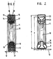
- Fig. 1 eine Bodenwalze in der Ansicht von hinten, ohne Stützkörper.
- Fig. 2 eine andere Ausführungsform des Gummireifens, wobei innerhalb der Gummireifen ein fester, umlaufender Ring angeordnet ist, in Schnittdarstellung,
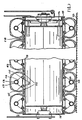
- Fig. 3 die als Fahrwerk einer Drillmaschine ausgebildete erfindungsgemäße Bodenwalze in Kombination mit einem Bodenbearbeitungsgerät in Betriebsstellung,
- Fig. 4 die als Fahrwerk einer Drillmaschine ausgebidete Bodenwalze gemäß Fig. 4 in verschwenkter Position,
- Fig. 5 eine erfindungsgemäße Bodenwalze, die als Fahrwerk einer hinter einem Bodenbearbeitungsgerät angeordneten Drillmaschine ausgebildet ist, in der Seitenansicht,
- Fig. 6 eine erfindungsgemäße Bodenwalze in Schnittdarstellung,
- Fig. 7 eine weitere Bodenwalze in Schnittdarstellung,
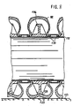
- Fig. 8 eine weitere Bodenwalze in Schnitt- und in Teilansicht,
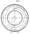
- Fig. 9 die Montage des Abstützringes gemäß Fig. 9 in einen Gummireifen,
- Fig. 10 eine weitere Bodenwalze im Schnitt und in der in der Seitenansicht,
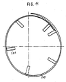
- Fig. 11 die Montage des Außenringes des Abstützringes,
- Fig. 12 eine Gerätekombination mit einer erfindungsgemäßenBodenwalze in der Seitenansicht,
- Fig. 13 die Bodenwalze in der Ansicht II-II mit aufgebauter Sämaschine,
- Fig. 14 die Bodenwalze in der Ansicht von hinten ausschnittsweise und teilweise im Schnitt,
- Fig. 15 die Bodenwalze in der Ansicht von hinten in Teilansicht und teilweise im Schnitt mit der streifenweisen Verfestigung des Bodens in Prinzipdarstellung,
- Fig. 16 die Darstellung der streifenweisen unterschiedlichen Verfestigung durch die erfindungsgemäße Bodenwalze entsprechend Fig. 16 in Prinzipdarstellung,
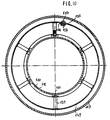
- Fig. 17 die innerhalb der Gummireifen angeordneten Abstützringe in der Seitenansicht und
- Fig. 18 die Abstützringe in der Ansicht VII - VII.
- Fig. 1 is a bottom roller in the view from behind, without support body.
- 2 shows another embodiment of the rubber tire, a fixed circumferential ring being arranged within the rubber tire, in a sectional view,
- 3 shows the ground roller according to the invention designed as the chassis of a seed drill in combination with a soil cultivation device in the operating position,
- 4 shows the bottom roller designed as the chassis of a seed drill according to FIG. 4 in the pivoted position,
- 5 shows a bottom roller according to the invention, which is designed as the chassis of a seed drill arranged behind a tillage implement, in a side view,
- 6 a bottom roller according to the invention in a sectional view,
- 7 is a further bottom roller in a sectional view,
- 8 is a further bottom roller in a sectional and partial view,
- 9 the assembly of the support ring according to FIG. 9 in a rubber tire,
- 10 is a further bottom roller in section and in the side view,
- 11 the assembly of the outer ring of the support ring,
- 12 shows a device combination with a floor roller according to the invention in side view,
- 13 the bottom roller in view II-II with the seed drill installed,
- 14 the bottom roller in the view from the rear in part and partly in section,
- 15 the bottom roller in the view from the rear in partial view and partially in section with the strip-wise consolidation of the bottom in a basic illustration,
- 16 shows the basic consolidation according to FIG. 16 of the different consolidation in strips by the bottom roller according to the invention,
- 17 the support rings arranged inside the rubber tires in side view and
- Fig. 18, the support rings in the view VII - VII.
Die Bodenwalze 1 weist ein als zentrales Tragrohr 2 ausgebildetes Traggerüst auf, welches drehbar in dem Tragrahmen 3 gelagert ist. Dieser Tragrahmen 3 weist die Anschlußelemente 4 und 5 zum Ankuppeln an eine Bodenbearbeitungsmaschine auf. Das Anschlußelement 4 befindet sich an einem aus einem Rohr hergestellten Bügel 6, der an der Vorderseite der Bodenwalze 1 angeordnet ist. Die Anschlußelemente 5 befinden sich an dem sich über die gesamte Breite der Bodenwalze erstreckenden Rohr 7, daß auf der in Fahrtrichtung gesehen hinteren Seite der Bodenwalze 1 an Teilen des Tragrahmens 3 angeschweißt ist. Die Anschlußelemente 5 werden von jeweils zwei auf dem Rohr 7 angeschweißten Platten 8 begrenzt. Auf dem zentralen Tragrohr 2 sind über die gesamte Arbeitsbreite der Bodenwalze 1 die Gummireifen 9 derart angeordnet, daß sie einen gewissen Abstand zueinander aufweisen. Die Gummireifen 9 sind jeweils auf den Felgen 10 angeordnet. Diese Felgen 10 sind über dreieckförmig angeordneten Streben 11 mit zentralen Tragrohr 2 verbunden. Die auf dem zentralen Tragrohr 2 angeordneten Gummireifen 9 können beim Abrollen auf dem Boden 12 walken, so daß sich die Gummireifen 9 selbst reinigen.The bottom roller 1 has a support frame designed as a
Dieser Schaumstoff 13 weist eine progressive Federkennlinie auf. Der Gummireifen 9 ist derart ausgeschäumt, daß der Außenbereich 15 im Bereich der Lauffläche 16 des Gummireifens 9 relativ weich und der innere Bereich 17 fest ist. Die unterschiedliche Festigkeit des Schaumstoffes 13 wird durch unterschiedlich große Lufteinschlüsse 14 erreicht. Der feste Schaumstoff 13 des inneren Bereiches 17 sorgt dafür, daß der Wulst 18 des Reifens 9 immer gegen das Felgenhorn 19 der Felge 10 gedrückt wird. Der feste Schaumstoff 13 im inneren Bereich 17 sorgt also für eine sichere Befestigung des Gummireifens 9 auf der Felge 10, so daß der Gummireifen 9 nicht von der Felge 10 abspringen kann. Die im Außenbereich 15 der Lauffläche 16 des Gummireifens 9 angeordnete weiche Schaumstoffmasse 20 wirkt der Verformung des Reifens 9 in seiner Aufstandsfläche 21 auf den Boden 12 entgegen. Hierdurch wird dem Außenbereich 15 der Lauffläche 16 eine für die optimale Walzwirkung benötigte Starrheit verliehen, die es dem Gummireifen 9 beim Abrollen auf dem Boden 12 aber immer noch erlaubt zu walken, so daß einerseite eine vorzügliche Krümelung und Andrückwirkung bei der Saatbettbereitung erreicht wird und andererseits gleichzeitig ein vorzüglicher Selbstreinigungseffekt der Reifen 9 gewährleistet ist.This
Die Fig. 2 zeigt einen weiteren Gummireifen 9, wobei innerhalb dieses Gummireifens 9 ein fester umlaufender Ring 22 angeordnet ist, der einen etwas kleineren Außendurchmesser d als der innere Außendurchmesser D des Gummireifens 9 aufweist. Dieser Ring 22 weist eine dem Gummireifen 9 annähernd entsprechende Kontur auf. Der Gummireifen 9 ist über Befestigungs- und Klemmelemente 23 mit der Felge 10 verbunden. Hierbei drücken die Befestigungs- und Klemmelemente 23 den Wulst 18 des Reifens 9 gegen das Felgenhorn 19 der Felge 10, so daß ein Abspringen der Reifen 9 von der Felge 10 nicht möglich ist. Während des Abrollens der Gummireifen 9 auf dem Boden 12 begrenzt der umlaufende Ring 22 das Verformen der Gummireifen 9. Der Außendurchmesser d des umlaufenden Ringes 22 stellt somit den wirksamen Walzendurchmesser der einzelnen Gummireifen 9 dar.FIG. 2 shows a
Die Fig. 3 und 4 zeigen die Bodenwalze 1, die als Laufwerk für die Sämaschine 24 ausgebildet ist. Der Vorratsbehälter 25 der Sämaschine 24 ist im wesentlichen dicht oberhalb der Bodenwalze 1 angeordnet. Dicht hinter der Bodenwalze 1 ist über die Tragarme 26 die Scharhalteschiene 27 befestigt, an der in zwei hintereinander liegenden Querreihen die Säschare 28 angelenkt sind, die das von den Dosierelementen 29 der Sämaschine 24 dosierte Saatgut in den Boden 12 ablegen. Die Dosierelemente 29 der Sämaschine 24 werden über den Kettentrieb 30 über das stufenlos einstellbare Regelgetriebe 31 von der Bodenwalze 1 angetrieben. Mit Hilfe der an den Bügel 6 angeordneten Dreipunktkupplungselemente 32 läßt sich die auf der Bodenwalze 1 angeordnete Sämaschine 24 mit dem Dreipunktkraftheber eines die Bodenwalze 1 samt Sämaschine 24 tragenden Schleppers anbringen.3 and 4 show the bottom roller 1, which is designed as a drive for the
Die auf einer Bodenwalze 1 aufgesattelte Sämaschine 24 läßt sich aber auch in Kombination mit einem Bodenbearbeitungsgerät verwenden. Die in die Sämaschine 24 integrierte Bodenwalze 1 läßt sich über die Tragarme 33 und die Kupplungsvorrichtung 34 mit dem Bodenbearbeitungsgerät verbinden. Durch das hintereinander Anordnen von Bodenbearbeitungsgerät und Sämaschine 24 entsteht die Bestellkombination 35.The
Die Bestellkombination 35 weist beispielsweise ein als Kreiselgrubber 36 ausgebildetes Bodenbearbeitungsgerät auf, das über die Tragarme 33 und der als hydraulische Schwenkvorrichtung 37 mit dem Hydraulikzylinder 38 ausgebildeten Kupplungseinrichtung 34 mit der Sämaschine 24 verbunden ist. Die Tragarme 33 werden an den Anschlußelementen 5, die auf dem Rohr 7 hinter der Bodenwalze 1 angeordnet sind, befestigt. Die Sämaschine 24 ist um dieses Rohr 7 mit Hilfe der hydraulischen Schwenkeinrichtung 37 schwenkbar, so daß die Säschare 28 durch Verschwenken der Sämaschine 24 gemäß Fig. 5 in eine Position verschwenkbar sind, in der sie einen großen Abstand zur Bodenoberfläche 12 aufweisen.The
Die Bodenwalze 1 läßt sich auch als reine Nachlaufwalze hinter einem Bodenbearbeitungsgerät einsetzen, wobei sie ebenfalls über die Tragarme 33 in einfacher Weise mit dem Bodenbearbeitungsgerät verbindbar ist.The bottom roller 1 can also be used as a pure trailing roller behind a soil tillage implement, whereby it can also be connected to the soil tillage implement in a simple manner via the
Die Erfindung beschränkt sich nicht nur auf die angeführten Ausführungsbeispiele, sondern berücksichtigt alle zum Verfestigen eines Bodens oder einer Bodenoberfläche geeigneten Walzen bzw. Walzkörper, die in den Schutzbereich der Patentansprüche fallen.The invention is not limited to the exemplary embodiments mentioned, but takes into account all rollers or roller bodies suitable for solidifying a soil or a soil surface, which fall within the scope of protection of the patent claims.
Die Fig. 5 zeigt eine landwirtschaftliche Gerätekombination, die aus der schleppergetriebenen Bodenbearbeitungsmaschine 101 und der hinter der Bodenbearbeitungsmaschine 101 über das Dreipunktgestänge 102 angeordneten Bodenwalze 103 mit der aufgesattelten Drillmaschine 104 besteht. Die Bodenwalze 103 ist somit als Nachlaufwalze hinter der Bodenbearbeitungsmaschine 101 und gleichzeitig als Fahrwerk für die Drillmaschine 104 ausgebildet. Die Drillmaschine 104 weist die Säschare 105 und den Saatstriegel 106 auf. Von der Bodenwalze 103 aus werden über den regelbaren Antrieb 107 die Dosierorgane 108 der Drillmaschine angetrieben.FIG. 5 shows an agricultural implement combination consisting of the tractor-driven
Die Bodenwalze 103 besteht aus den nebeneinander angeordneten Gummireifen 109, die auf dem drehbar gelagerten Traggerüst 110 angeordnet sind. Das Traggerüst 110 ist als Tragrohr ausgebildet, welches über die Lager 111 und die Lagerzapfen 112 an den seitlichen Tragarmen 113 und 114 dreh- bar angeordnet ist, wobei der Tragarm 114 als Lagergehäuse für den Antrieb 115 des Regelgetriebes 107 ausgebildet ist.The
Auf dem durchgehenden Tragrohr 110 sind die Gummireifen 109 nebeneinander angeordnet. Das Tragrohr 110 weist einen Außendurchmesser A auf, der in etwa dem Innendurchmesser B der Gummireifen 109 entspricht. Somit sind also die Gummireifen 109 sehr einfach auf dem Tragrohr 110 von der einen Seite her aufzuschieben. An der rechten Seite des Tragrohres 110 ist der Stirnring 115 mittels der als Spannvorrichtung ausgebildeten Schrauben 116 anzuordnen. Auf der anderen Seite des Tragrohres 110 ist die Stirnwand 117 an der Stirnfläche des Tragrohres 110 angeschweißt.The
Der Außendurchmesser der Stirnwand 117 is größer als die Außendurchmesser A des Tragrohres, so daß die überstehende Ring 118 als Anlagefläche für den Wulst 119 dient. Ebenfalls weist der Stirnring 115 einen größeren Außendurchmesser als das Tragrohr 110 auf, damit auch der überstehende Ring 120 des Stirnringes 117 als Anlagefläche für den Wust 119 des Gummireifens 109 dient.The outer diameter of the
In dem Innern der Gummireifen 109 sind die Abstandsringe 121 angeordnet. Die Abstandsringe 121 weisen einen Innendurchmesser auf, der zumindest etwa dem Innendurchmesser der Gummireifen 109 sowie dem Außendurchmesser A des Tragrohres 110 entspricht. Die Abstandsringe 121 bestehen aus zwei kreisförmig gebogenen Rundstäben, die über mindestens drei Stege 122 in einem Abstand zueinander miteinander verbunden sind. An den Stegen der Abstandsringe 121 sind über die Stege 123 jeweils die Abstützringe 124 mit den Schrauben 125 befestigt. Die Abstützringe sind aus drei Teilen zusammengesetzt. Zwischen der Außenfläche des Abstützringes 124 und der Innenfläche der Lauffläche des Gummireifens 109 ist ein Abstand C vorhanden, der etwa 3/10 der Höhe H der Gummireifenseitenwand 126 entspricht. Hierdurch ist es möglich, daß der Gummireifen 109 beim Abrollen auf der Bodenoberfläche 127 wie in Fig. 7 dargestellt, sich zusammendrücken bzw. walken kann, wobei die Innenflächen 128 der Laufflächen 129 des Gummireifens 9 sich auf den Abstützring 124 abstützen kann, damit der Gummireifen 109 beim Abrollen auf der Bodenoberfläche 127 nicht ganz zusammengedrückt wird und noch eine ausreichende Rückverfestigung des Bodens erreicht wird. Zwischen den einzelnen Gummireifen 109 ist jeweils der umlaufende Ring 130, der gemäß Fig. 7 aus zwei Rundstäben, die über die Stege 131 miteinander verbunden sind besteht, angeordnet. Durch die entsprechenden Breiten der Abstandringe 121 sowie der Abstandringe 130 werden die Reifen über die als Spannvorrichtung ausgebildeten Schrauben 116 und den Stirnrädern 115 sowie der Stirnwand 117 auf dem Tragrohr in seitlicher Richtung festgeklemmt.The spacer rings 121 are arranged in the interior of the
Es sei noch darauf hingewiesen, daß die Abstützringe 124 aus den kreisförmig gebogenen Segmentstücken bestehen und daß an diesen Segmentstücken die nach innen weisenden Stege 123 angeordnet sind, so daß die Abstützringe 124 sich über die Abstandsringe 121 auf dem Tragrohr 110 abstützen können.It should also be pointed out that the support rings 124 consist of the circularly curved segment pieces and that the inwardly pointing webs 123 are arranged on these segment pieces, so that the support rings 124 can be supported on the
Die Bodenwalze gemäß Fig. 7 unterscheidet sich von der Bodenwalze gemäß Fig. 6 nur dadurch, daß innerhalb der Gummireifen 109 die Abstandsringe 132 angeordnet sind, die eine größere Breite als die Abstandsringe 121 gemäß Fig. 7 aufweisen. Des weiteren sind die Stege 133, die die Abstandsringe 132 miteinander verbinden, geteilt ausgebildet. Die Stege 133 werden durch den Steg 134 über die Schrauben 135 miteinander verbunden. An dem Steg 134 sind die Segmentstücke 136 der Abstützringe 137 angeordnet Des weiteren ist zwischen den jeweils nebeneinander angeordneten Gummireifen 109 der einen kreisfömigen Querschnitt aufweisende Abstandsring 138 angeordnet, der gleichzeitig eine dichtende Funktion hat und somit verhindert, daß Erde von außen in das Innere der Gummireifen 109 eindringen kann. Die Gummireifen 109 werden also auf dem Tragrohr 110 festgeklemmt.The floor roller according to FIG. 7 differs from the floor roller according to FIG. 6 only in that the spacer rings 132, which have a greater width than the spacer rings 121 according to FIG. 7, are arranged within the
Bei der Bodenwalze gemäß Fig. 8 sind auf dem durchgehenden Tragrohr 110 die Gummireifen 109 nebeneinander angeordnet. Zwischen den nebeneinander angeordneten Gummireifen 109 sind die Abstandsringe 130 auf dem Tragrohr 110 angeordnet. In dem Innenraum der Gummireifen 109 ist jeweils der Abstützring 146, der einen doppelt T-förmigen Querschnitt aufweist, angeordnet. Diese Abstützringe 146 weisen einen Innendurchmesser auf, der in etwa dem Außendurchmesser des Tragrohres 110 sowie dem Innendurchmesser der Gummireifen 109 entspricht. Der Abstützring 146 besteht aus einem bei einer Temperatur über 70° verformbaren Thermoplastmaterial, welches bei normaler Betriebstemperatur ausreichend steif ist. Auf dem Abstützring 146 kann sich die Innenfläche 128 der Lauffläche 129 des Gummireifens 109 beim Abrollen auf der Bodenoberfläche 127 abstützen und noch ausreichend beim Abrollen auf der Bodenoberfläche 127 walken, so daß ein Selbstreinigungseffekt der Gummireifen 109 eintritt. Zur Montage bzw. zum Hineinbringen des Abstützringes 146 in den Innenraum des Gummireifens 109, wird der Abstützring 146 auf eine Temperatur von über 70° erwärmt, so daß er sich entsprechend der Fig. 9 wobei in der Fig. 9 nur die Außenkontur 147 des Abstützringes eingezeichnet ist, verformen läßt, so daß sich der Abstützring 146 leicht in den Innenraum des Gummireifens 109 schieben läßt. Nachdem Hineinbringen des Abstützringes 146 in den Innenraum des Gummireifens 109 wird der Abstützring 146 in seine normale Form gebracht, so daß er nach dem Abkühlen die gewünschte kreisförmige Form aufweist. Nach dem Abkühlen ist der Abstützring 146 ausreichend steif, so daß er die durch das Abrollen des Gummireifens 109 auf der Bodenoberfläche 127 auf ihn einwirkenden Kräfte übernehmen kann und so seine Abstützfunktion ausüben kann.8, the
Die Bodenwalze gemäß Fig. 10 weist die Gummireifen 109 auf die auf dem Tragrohr 110 angeordnet sind. Innerhalb der Gummireifen 109 ist jeweils der Abstützring 148 angeordnet Der Abstützring 148 besteht aus dem Außenring 149 und dem Innenring 150. An dem Außenring 149 sind die Stege 151 angeordnet. Die Stege 151 können entweder Rohrhülsen sein oder andere Hülsen, die an dem Außenring angeschweißt sind. An den Stegen 151 wird der Innenring 150 angeordnet. Hierzu weist der Innenring 150 im Bereich der Stege 151 Bohrungen auf, so daß der Innenring über die Schrauben 152 mit den Stegen 151 bzw. dem Außenring 149 zu verschrauben ist. Des weiteren ist der Außenring an der Stelle 153 geteilt und über das als Schraube 154 ausgebildete Verbindungselement zu verbinden. Der Innenring weist einen Innendurchmesser auf, der etwa dem Außendurchmesser des Tragrohres 110 entspricht. Die Montage bzw. das Anordnen des Abstützringes 148 innerhalb des Reifens 109 erfolgt folgendermaßen. Zunächst wird der Außenring, da er an der Stelle 153 geteilt ist, wie in Fig. 11 dargestellt zusammengedrückt, so daß er in den Reifen eingeführt werden kann. Anschließend wird der Außenring 149 auseinandergedrückt und mittels der Schraube 152 werden die beiden Enden 155 und 156 des Außenringes durch die Schrauben 154 miteinander verbunden. D.h. also, daß sich Teile des Außenringes überlappen müssen. Anschließend wird der Innenring in den Reifen 109 eingelegt und über die Schrauben 152 wird der Innenring mit den Stegen 151 verschraubt. Anschließend wird der Reifen mit dem Abstützring auf dem Tragrohr 110 angeordnet.The bottom roller according to FIG. 10 has the
Die Fig. 12 zeigt eine landwirtschaftliche Gerätekombination, die aus der schleppergetriebenen Bodenbearbeitungsmaschine 201 und der hinter der Bodenbearbeitungsmaschine 201 über das Dreipunktgestänge 202 angeordneten Bodenwalze 203 mit der aufgesattelten Drillmaschine 204 besteht. Die Bodenwalze 203 mit somit als Nachlaufwalze hinter der Bodenbearbeitungsmaschine 201 und gleichzeitig als Fahrwerk für die Drillmaschine 204 ausgebildet. Die Drillmaschine 204 weist die Säschare 205, die in zwei hintereinanderliegenden Querreihen angeordnet sind auf. Von der Bodenwalze 203 aus werden über den regelbaren Antrieb 206 die Dosierorgane 207 der Drillmaschine 204 angetrieben. Die Säschare 205 werden durch die Schardruckfedern 208 gegen den Boden gedrückt.FIG. 12 shows an agricultural implement combination consisting of the tractor-driven
Die Bodenwalze 203 besteht aus den nebeneinander angeordneten Gummireifen 209, die auf den drehbar gelagerten Traggerüst 210 angeordnet sind. Das Traggerüst 210 ist als Tragrohr ausgebildet, welches über die Lager 211 und die Lagerzapfen 212 an den seitlichen Tragarmen 213 und 214 drehbar angeordnet ist, wobei der Tragarm 214 als Lagergehäuse für den Antrieb 215 des Regelgetriebes 206 ausgebildet ist.The
Auf dem durchgehenden Tragrohr 210 sind die Gummireifen 209 nebeneinander angeordnet. Das Tragrohr 210 weist einen Außendurchmesser auf, der in etwa dem Innendurchmesser der Gummireifen 209 entspricht. Somit sind also die Gummireifen 209 sehr einfach auf dem Tragrohr 210 von der einen Seite her aufzuschieben. An der einen Seite des Tragrohres 210 ist ein Stirnring mittels einer als Spannvorrichtung ausgebildeten Schraube anzuordnen. Auf der anderen Seite des Tragrohres 210 ist eine Stirnwand an der Stirnfläche des Tragrohres angeschweißt. Der Außendurchmesser der Stirnwände ist größer als der Außendurchmesser des Tragrohres 210, so daß der überstehende Ring der Stirnwand als Anlagefläche für den Wulst der Reifen dient.The
In dem Innern der Gummireifen 209 sind die beiden Abstützringe 216 in einem Abstand zueinander angeordnet. Die Abstützringe 216 weisen einen Außendurchmesser auf, der kleiner ist als der Innendurchmesser der Lauffläche der Gummireifen 209. Die beiden Abstützringe 216 sind durch drei Abstandshalter 217 miteinander verbunden und auf Abstand zueinander angeordnet. In jedem Gummireifen 209 sind zwei über die Abstandshalter 217 miteinander verbundene Abstützringe 216 angeordnet. Die Abstützringe 16 sind in einem Abstand zueinander angeordnet, so daß zwischen den Abstützringen 216 in deren radialen Außenbereich sich der freie umlaufende Freiraum 218 befindet. Die Abstützringe sind dicht neben der Innerwand 219 des Reifens 209 angeordnet. Die Abstützringe 216 bestehen aus den drei zusammengesetzten Teilen, die an den Stellen 220 nach der Montage innerhalb des Reifens miteinander verschweißt werden. Die Abstützringe 216 weisen auf ihrer Außenseite 221 eine abgerundete Abstützfläche auf. Die Abstützringe 216 bestehen aus geformten Blechteilen.The two support rings 216 are arranged at a distance from one another in the interior of the
Der Abstand A zwischen den beiden innerhalb des Gummireifens 209 angeordneten Abstützringen 216 ist derart groß, daß die mittlere Lauffläche 222 des Reifens 209 in den Freiraum 218 zwischen diesen beiden Abstützringen 216 sich nach innen zumindest etwas hineindrücken kann.The distance A between the two support rings 216 arranged inside the
Hinter der Bodenwalze 203 sind die Säschare 205 derart angeordnet, daß jeweils ein Säschar 205 in Verlängerung, entgegen der Fahrtrichtung gesehen, eines Abstützringes 216, der im Inneren der Gummireifen 209 angeordnet ist, sich befindet. Des weiteren sind an dem Rahmen der Sämaschine 204 die Räumzinken 223 angeordnet, die jeweils in dem Zwischenraum 224 zwischen zwei einander benachbarten Gummireifen 209 ragen. Diese Räumzinken 223 sind etwa waagerecht angeordnet und befinden sich in einem Abstand zu den Zwischenstücken 225, welche sich zwischen den einander benachbarten Gummireifen 209 befinden. Durch die Zwischenstücke 225 und durch die durch die Abstandshalter 217 auf Abstand gehaltenen Abstützringe 216 wird sichergestellt, daß die Gummireifen 209 in einem ganz bestimmten und fixierten Abstand zueinander auf dem Tragrohr 210 angeordnet sind. Dadurch, daß durch die beiden äußeren Stirnwände 226 und 227 die Gummireifen gegeneinander gedrückt werden, wird sichergestellt, daß kein Erdreich in das Innere der Gummireifen 209 eindringen kann, da der Innenraum der Gummireifen durch das Gegeneinanderpressen der Gummireifen gegen die Zwischenstücke 225, die als Ringe ausgebildet sind, abgedichtet wird.Behind the
Die Zwischenringe 225 weisen einen derartigen Durchmesser und eine derartige Größe auf, daß sie in den Wulsteinschnitt 228 der Gummireifen 209 einfassen und so eine sichere Befestigung und ein sicheres Festklemmen der Gummireifen 209 auf dem Tragrohr 210 in jedem Falle, selbst bei Kurvenfahrten, gewährleisten. Damit das Festklemmen der Gummireifen durch die Zwischenringe 225 und durch die Abstützringe 216 noch besser gewährleistet werden kann, ist der sich gegenüber dem Außenwulst 229 auf der Innenseite befindende Innenwulst mit geeigneten Mitteln herausgeschnitten, so daß sich auf der Innenseite des Reifens 209 gegenüber dem Außenwulst 229 eine ebene Fläche ergibt. Hierdurch wird ein sicheres Festklemmen der Gummireifen 209, welche herkömmliche und gebrauchte PKW-Reifen in bevorzugter Weise sind, erreicht.The
Die Funktion der Bodenwalze 203 mit den in einem Abstand zueinander angeordneten Abstützringen 216 im Inneren des Gummireifens 209 ist folgende:The function of the
Durch die vorlaufende Bodenbearbeitungsmaschine 201 wird der Boden aufgelockert und gekrümelt. Die nachfolgende Bodenwalze 203 verdichtet den Boden in streifenförmig unterschiedlich starker Weise. Im Bereich der Abstandsringe 216 ergeben die sich mit enger Schraffur gekennzeichneten stark verfestigten Verfestigungsbereiche 230. In diesen Streifen 230 wird der Boden derart stark verdichtet, daß die durch die mit Kreise angedeuteten Säschare 205 abgelegten Samenkörner optimale Keim- und Wachstumsbedingungen bereits in den ersten Wochen vor dem vollkommenen Absetzen des Bodens aufgrund des natürlichen Absetzvorganges vorfinden. In dem Bereich 231 zwischen den stark verfestigten Bereichen 230 in dem Bereich zwischen den beiden Abstützringen 216 innerhalb eines Gummireifens, wird ein etwas weniger stark verfestigter Bodenstreifen 231 erzeugt. In dem Bereich 231 drückt die Lauffläche des Gummireifens 209 sich in den Zwischenraum 218 zwischen den Abstützringen 216 nach innen. Nach dem Abrollen der Lauffläche des Gummireifens 209 auf dem Boden wird dieser mittlere, sich beim Abrollen auf der Bodenoberfläche in den Zwischenraum 218 zwischen den Abstützringen 216 hineindrückende Bereich aufgrund der Elastizität des Gummireifens wieder nach außen drücken. Diese Bewegung der Lauffläche des Gummireifens wird als Walken bezeichnet. Durch dieses derartig starke walken der Lauffläche des Gummireifens 209 ergibt sich in vorteilhafter Weise eine Selbstreinigung der Lauffläche des Gummireifens 209. Der nicht so stark verfestigte Bodenstreifen 231 setzt sich aufgrund des natürlichen Absetzvorganges des aufgelockerten Bodens in wenigen Wochen weiter; so daß in wenigen Wochen, wenn die Wurzeln der in den stark verfestigten Bodenbereichen 230 abgelegten Samenkörner in den Bereich 231 hineinwachsen, auch diese Wurzeln einen optimal verfestigten Boden in diesem Bereich 231 vor. Zwischen den einander benachbarten Reifen 209 entsteht jeweils der nur leicht verfestigte Bodenstreifen 232. Einige Wochen, nachdem die Streifen 231 ihren optimalen Verfestigungsgrad aufgrund des natürlichen Absetzvorganges erreicht haben, erreichen auch die nur leicht oder gar nicht verfestigten Bodenstreifen 232 den optimal verfestigten Verfestigungsgrad, so daß dann die in diesem Bereich hineinwachsenden Wurzeln auch noch nach weiterer Zeit einen optimal verfestigten Boden vorfinden. Somit ist also durch die erfindungsgemäße Bodenwalze gewährleistet, daß über einen sehr langen Zeitraum die Wurzeln des Saatgutes bzw. das Saatgut selbst in optimal verfestigtem Boden aufwachsen kann. U.U. kann es sinnvoll sein, die Säschare 205 nicht genau in der Mitte der stark verfestigten Bodenstreifen 230, sondern etwas seitlich versetzt und zwar in Richtung der weniger stark verfestigten Bodenstreifen 231 anzuordnen.The soil is loosened and crumbled by the advancing
Claims (26)
Priority Applications (1)
| Application Number | Priority Date | Filing Date | Title |
|---|---|---|---|
| AT87105081T ATE46239T1 (en) | 1986-05-13 | 1987-04-06 | GROUND ROLLER. |
Applications Claiming Priority (6)
| Application Number | Priority Date | Filing Date | Title |
|---|---|---|---|
| DE3616021 | 1986-05-13 | ||
| DE19863616021 DE3616021A1 (en) | 1986-05-13 | 1986-05-13 | Soil roller |
| DE19863631462 DE3631462A1 (en) | 1986-09-16 | 1986-09-16 | Ground roller |
| DE3631462 | 1986-09-16 | ||
| DE3705952 | 1987-02-25 | ||
| DE19873705952 DE3705952A1 (en) | 1986-09-16 | 1987-02-25 | Ground roller |
Publications (3)
| Publication Number | Publication Date |
|---|---|
| EP0245648A1 EP0245648A1 (en) | 1987-11-19 |
| EP0245648B1 EP0245648B1 (en) | 1989-09-13 |
| EP0245648B2 true EP0245648B2 (en) | 1992-04-29 |
Family
ID=27194360
Family Applications (1)
| Application Number | Title | Priority Date | Filing Date |
|---|---|---|---|
| EP87105081A Expired - Lifetime EP0245648B2 (en) | 1986-05-13 | 1987-04-06 | Soil roller |
Country Status (6)
| Country | Link |
|---|---|
| EP (1) | EP0245648B2 (en) |
| AT (1) | ATE46239T1 (en) |
| DE (1) | DE3760540D1 (en) |
| DK (1) | DK172286B1 (en) |
| ES (1) | ES2010684B3 (en) |
| GR (2) | GR3000190T3 (en) |
Cited By (2)
| Publication number | Priority date | Publication date | Assignee | Title |
|---|---|---|---|---|
| EP3017669B1 (en) | 2014-11-10 | 2017-06-28 | Otico | Improved agricultural wheel |
| EP3984782A1 (en) | 2020-10-16 | 2022-04-20 | Otico | Kit for forming an agricultural tool from a wheel body or a tubular support |
Families Citing this family (14)
| Publication number | Priority date | Publication date | Assignee | Title |
|---|---|---|---|---|
| EP0299190B1 (en) * | 1987-07-17 | 1990-08-22 | Amazonen-Werke H. Dreyer GmbH & Co. KG | Soil roller |
| DE3815280A1 (en) * | 1988-05-05 | 1989-11-30 | Amazonen Werke Dreyer H | GROUND ROLLER |
| DE8902722U1 (en) * | 1988-12-23 | 1989-05-03 | Rabewerk Heinrich Clausing, 4515 Bad Essen | Field roller |
| DE3900819A1 (en) * | 1989-01-13 | 1990-07-19 | Amazonen Werke Dreyer H | GROUND ROLLER |
| DE3901883A1 (en) * | 1989-01-23 | 1990-07-26 | Amazonen Werke Dreyer H | GROUND ROLLER |
| DE3918751A1 (en) * | 1989-06-08 | 1990-12-13 | Amazonen Werke Dreyer H | GROUND ROLLER |
| FR2730599B1 (en) * | 1995-02-21 | 1997-04-18 | Hamot Michel | AGRAR TIRE ROLLER |
| DE19707004B4 (en) * | 1997-02-21 | 2008-04-03 | Amazonen-Werke H. Dreyer Gmbh & Co. Kg | ground roller |
| FR2776239B1 (en) * | 1998-03-18 | 2000-06-09 | Otico | TIRE FOR SPECIAL PURPOSES, PARTICULARLY FOR AGRICULTURAL EQUIPMENT |
| DE102006022537A1 (en) * | 2006-05-15 | 2007-11-22 | Amazonen-Werke H. Dreyer Gmbh & Co. Kg | Agricultural soil roller with a support body |
| DE102009007202A1 (en) | 2009-02-03 | 2010-08-05 | Amazonen-Werke H. Dreyer Gmbh & Co. Kg | Agricultural base roller, has rigid supporting body made of elastic and/or flexible material and comprising circular race ring that is arranged on outer circular region of supporting body |
| EA201491654A1 (en) * | 2012-04-23 | 2015-04-30 | Амазонен-Верке Х. Дрейер Гмбх Энд Ко. Кг | AGRICULTURAL MACHINE |
| EP3175695A1 (en) * | 2015-12-03 | 2017-06-07 | Horsch Maschinen GmbH | Firming wheel for seeder |
| DE102017113201A1 (en) | 2017-06-15 | 2018-12-20 | Amazonen-Werke H. Dreyer Gmbh & Co. Kg | ground roller |
Family Cites Families (12)
| Publication number | Priority date | Publication date | Assignee | Title |
|---|---|---|---|---|
| FR1261329A (en) * | 1960-04-05 | 1961-05-19 | Cima | Manufacturing process of rollers for agricultural use in flexible material provided with helical grooves |
| US3181622A (en) * | 1963-12-31 | 1965-05-04 | Sperry Rand Corp | Press wheel |
| US3339643A (en) * | 1964-09-11 | 1967-09-05 | Scarborough Troy | Soil working machine |
| FR88787E (en) * | 1965-06-29 | 1967-06-07 | ||
| US3635273A (en) * | 1969-10-09 | 1972-01-18 | Theodore C Patecell | Flat tire safety roller and warning indicator |
| DE2001062A1 (en) * | 1970-01-12 | 1971-07-22 | Eicher Traktor Landmasch | Seed drill |
| US3777797A (en) * | 1972-05-26 | 1973-12-11 | H Anderson | Safety support for pneumatic tires |
| FR2347863A1 (en) * | 1976-04-12 | 1977-11-10 | Pello Andre | Agricultural roller with row of pneumatic tyres - has support wheels fixed to shaft mounted in frame with hitches for ganging |
| FR2525066A1 (en) * | 1982-04-14 | 1983-10-21 | Kuhn Sa | ROLL OF FLOOR WORKING |
| DE3218635A1 (en) * | 1982-05-18 | 1983-11-24 | Franz Kirchberger | Packer roller for ground-working in agriculture |
| US4489790A (en) * | 1982-12-15 | 1984-12-25 | Leonard Lattin | Seed planter press wheel |
| DE3573503D1 (en) * | 1984-05-02 | 1989-11-16 | Kuhn Sa | Agricultural implements for soil cultivation |
-
1987
- 1987-04-06 EP EP87105081A patent/EP0245648B2/en not_active Expired - Lifetime
- 1987-04-06 DE DE8787105081T patent/DE3760540D1/en not_active Expired
- 1987-04-06 AT AT87105081T patent/ATE46239T1/en not_active IP Right Cessation
- 1987-04-06 ES ES87105081T patent/ES2010684B3/en not_active Expired
- 1987-05-13 DK DK243987A patent/DK172286B1/en active
-
1989
- 1989-10-24 GR GR89400211T patent/GR3000190T3/en unknown
-
1992
- 1992-07-29 GR GR920401638T patent/GR3005306T3/el unknown
Cited By (5)
| Publication number | Priority date | Publication date | Assignee | Title |
|---|---|---|---|---|
| EP3017669B1 (en) | 2014-11-10 | 2017-06-28 | Otico | Improved agricultural wheel |
| US10343458B2 (en) | 2014-11-10 | 2019-07-09 | Otico | Agricultural wheel |
| EP3017669B2 (en) † | 2014-11-10 | 2020-11-18 | Otico | Improved agricultural wheel |
| EP3984782A1 (en) | 2020-10-16 | 2022-04-20 | Otico | Kit for forming an agricultural tool from a wheel body or a tubular support |
| FR3115233A1 (en) | 2020-10-16 | 2022-04-22 | Otico | Kit to form an agricultural tool from a wheel body or a tubular support |
Also Published As
| Publication number | Publication date |
|---|---|
| GR3000190T3 (en) | 1990-12-31 |
| DK172286B1 (en) | 1998-03-02 |
| ATE46239T1 (en) | 1989-09-15 |
| ES2010684B3 (en) | 1989-12-01 |
| GR3005306T3 (en) | 1993-05-24 |
| EP0245648A1 (en) | 1987-11-19 |
| EP0245648B1 (en) | 1989-09-13 |
| DK243987D0 (en) | 1987-05-13 |
| DE3760540D1 (en) | 1989-10-19 |
| DK243987A (en) | 1987-11-14 |
Similar Documents
| Publication | Publication Date | Title |
|---|---|---|
| EP0245648B2 (en) | Soil roller | |
| EP0223134B2 (en) | Landroller | |
| DE69306757T2 (en) | AGRICULTURAL IMPROVEMENTS | |
| DE2030448C2 (en) | Ground cultivation machine with driven components - has pressure roll formed by plate wheels with smaller scraper wheels between | |
| DE2162434A1 (en) | Pressure device for compacting a machined strip of terrain | |
| EP0445582B1 (en) | Groundworking implement | |
| DE9010178U1 (en) | Agricultural soil roller | |
| DE29714699U1 (en) | Disc harrow | |
| EP1310144B1 (en) | Soil working tool for levelling, crumbling and consolidating the soil | |
| EP0676124B1 (en) | Toothed packer roller for precision drills and ground rollers | |
| EP0011732B1 (en) | Soil-working implement | |
| DE3705952A1 (en) | Ground roller | |
| EP0598311A2 (en) | Device and method of compacting soil for agricultural ground working and sowing | |
| EP0299190B1 (en) | Soil roller | |
| DE3631462A1 (en) | Ground roller | |
| DE2945896C2 (en) | Equipment combination for seedbed preparation | |
| DE202008014705U1 (en) | Device for preparing the soil for sowing and for spreading seed | |
| EP0401592A1 (en) | Ground roller | |
| EP0377885B1 (en) | Ground roller and tyre for such a ground roller | |
| EP0340548A1 (en) | Soil roller | |
| DE1757136A1 (en) | Farm roller | |
| DE3815279A1 (en) | Ground roller | |
| DE3616021A1 (en) | Soil roller | |
| DE3327362A1 (en) | TILLAGE MACHINE | |
| DE8706550U1 (en) | Soil roller |
Legal Events
| Date | Code | Title | Description |
|---|---|---|---|
| PUAI | Public reference made under article 153(3) epc to a published international application that has entered the european phase |
Free format text: ORIGINAL CODE: 0009012 |
|
| AK | Designated contracting states |
Kind code of ref document: A1 Designated state(s): AT BE CH DE ES FR GB GR IT LI LU NL SE |
|
| 17P | Request for examination filed |
Effective date: 19880513 |
|
| 17Q | First examination report despatched |
Effective date: 19890213 |
|
| GRAA | (expected) grant |
Free format text: ORIGINAL CODE: 0009210 |
|
| AK | Designated contracting states |
Kind code of ref document: B1 Designated state(s): AT BE CH DE ES FR GB GR IT LI LU NL SE |
|
| REF | Corresponds to: |
Ref document number: 46239 Country of ref document: AT Date of ref document: 19890915 Kind code of ref document: T |
|
| ET | Fr: translation filed | ||
| GBT | Gb: translation of ep patent filed (gb section 77(6)(a)/1977) | ||
| REF | Corresponds to: |
Ref document number: 3760540 Country of ref document: DE Date of ref document: 19891019 |
|
| ITF | It: translation for a ep patent filed | ||
| PGFP | Annual fee paid to national office [announced via postgrant information from national office to epo] |
Ref country code: LU Payment date: 19900424 Year of fee payment: 4 |
|
| PG25 | Lapsed in a contracting state [announced via postgrant information from national office to epo] |
Ref country code: LU Free format text: LAPSE BECAUSE OF NON-PAYMENT OF DUE FEES Effective date: 19900430 |
|
| PLBI | Opposition filed |
Free format text: ORIGINAL CODE: 0009260 |
|
| REG | Reference to a national code |
Ref country code: GR Ref legal event code: FG4A Free format text: 3000190 |
|
| 26 | Opposition filed |
Opponent name: RABEWERK GMBH + CO. Effective date: 19900507 |
|
| NLR1 | Nl: opposition has been filed with the epo |
Opponent name: RABEWERK GMBH |
|
| ITTA | It: last paid annual fee | ||
| PUAH | Patent maintained in amended form |
Free format text: ORIGINAL CODE: 0009272 |
|
| STAA | Information on the status of an ep patent application or granted ep patent |
Free format text: STATUS: PATENT MAINTAINED AS AMENDED |
|
| 27A | Patent maintained in amended form |
Effective date: 19920429 |
|
| AK | Designated contracting states |
Kind code of ref document: B2 Designated state(s): AT BE CH DE ES FR GB GR IT LI LU NL SE |
|
| REG | Reference to a national code |
Ref country code: CH Ref legal event code: AEN |
|
| NLR2 | Nl: decision of opposition | ||
| GBTA | Gb: translation of amended ep patent filed (gb section 77(6)(b)/1977) | ||
| ITF | It: translation for a ep patent filed | ||
| ET3 | Fr: translation filed ** decision concerning opposition | ||
| NLR3 | Nl: receipt of modified translations in the netherlands language after an opposition procedure | ||
| PGFP | Annual fee paid to national office [announced via postgrant information from national office to epo] |
Ref country code: GR Payment date: 19930211 Year of fee payment: 7 |
|
| PGFP | Annual fee paid to national office [announced via postgrant information from national office to epo] |
Ref country code: ES Payment date: 19930216 Year of fee payment: 7 |
|
| REG | Reference to a national code |
Ref country code: GR Ref legal event code: FG4A Free format text: 3005306 |
|
| PGFP | Annual fee paid to national office [announced via postgrant information from national office to epo] |
Ref country code: SE Payment date: 19930415 Year of fee payment: 7 Ref country code: AT Payment date: 19930415 Year of fee payment: 7 |
|
| PGFP | Annual fee paid to national office [announced via postgrant information from national office to epo] |
Ref country code: BE Payment date: 19930419 Year of fee payment: 7 |
|
| PGFP | Annual fee paid to national office [announced via postgrant information from national office to epo] |
Ref country code: CH Payment date: 19930625 Year of fee payment: 7 |
|
| PG25 | Lapsed in a contracting state [announced via postgrant information from national office to epo] |
Ref country code: AT Effective date: 19940406 |
|
| PG25 | Lapsed in a contracting state [announced via postgrant information from national office to epo] |
Ref country code: SE Effective date: 19940407 Ref country code: ES Free format text: LAPSE BECAUSE OF NON-PAYMENT OF DUE FEES Effective date: 19940407 |
|
| PG25 | Lapsed in a contracting state [announced via postgrant information from national office to epo] |
Ref country code: LI Effective date: 19940430 Ref country code: CH Effective date: 19940430 Ref country code: BE Effective date: 19940430 |
|
| BERE | Be: lapsed |
Owner name: AMAZONEN-WERKE H. DREYER G.M.B.H. & CO. K.G. Effective date: 19940430 |
|
| PG25 | Lapsed in a contracting state [announced via postgrant information from national office to epo] |
Ref country code: GR Free format text: THE PATENT HAS BEEN ANNULLED BY A DECISION OF A NATIONAL AUTHORITY Effective date: 19941031 |
|
| REG | Reference to a national code |
Ref country code: CH Ref legal event code: PL |
|
| EUG | Se: european patent has lapsed |
Ref document number: 87105081.1 Effective date: 19941110 |
|
| REG | Reference to a national code |
Ref country code: GR Ref legal event code: MM2A Free format text: 3005306 |
|
| REG | Reference to a national code |
Ref country code: ES Ref legal event code: FD2A Effective date: 19990201 |
|
| PGFP | Annual fee paid to national office [announced via postgrant information from national office to epo] |
Ref country code: GB Payment date: 20010323 Year of fee payment: 15 |
|
| REG | Reference to a national code |
Ref country code: GB Ref legal event code: IF02 |
|
| PG25 | Lapsed in a contracting state [announced via postgrant information from national office to epo] |
Ref country code: GB Free format text: LAPSE BECAUSE OF NON-PAYMENT OF DUE FEES Effective date: 20020406 |
|
| PGFP | Annual fee paid to national office [announced via postgrant information from national office to epo] |
Ref country code: NL Payment date: 20020425 Year of fee payment: 16 |
|
| GBPC | Gb: european patent ceased through non-payment of renewal fee |
Effective date: 20020406 |
|
| PGFP | Annual fee paid to national office [announced via postgrant information from national office to epo] |
Ref country code: DE Payment date: 20030410 Year of fee payment: 17 |
|
| PGFP | Annual fee paid to national office [announced via postgrant information from national office to epo] |
Ref country code: FR Payment date: 20030417 Year of fee payment: 17 |
|
| PG25 | Lapsed in a contracting state [announced via postgrant information from national office to epo] |
Ref country code: NL Free format text: LAPSE BECAUSE OF NON-PAYMENT OF DUE FEES Effective date: 20031101 |
|
| NLV4 | Nl: lapsed or anulled due to non-payment of the annual fee |
Effective date: 20031101 |
|
| PG25 | Lapsed in a contracting state [announced via postgrant information from national office to epo] |
Ref country code: DE Free format text: LAPSE BECAUSE OF NON-PAYMENT OF DUE FEES Effective date: 20041103 |
|
| PG25 | Lapsed in a contracting state [announced via postgrant information from national office to epo] |
Ref country code: FR Free format text: LAPSE BECAUSE OF NON-PAYMENT OF DUE FEES Effective date: 20041231 |
|
| REG | Reference to a national code |
Ref country code: FR Ref legal event code: ST |
|
| PG25 | Lapsed in a contracting state [announced via postgrant information from national office to epo] |
Ref country code: IT Free format text: LAPSE BECAUSE OF NON-PAYMENT OF DUE FEES;WARNING: LAPSES OF ITALIAN PATENTS WITH EFFECTIVE DATE BEFORE 2007 MAY HAVE OCCURRED AT ANY TIME BEFORE 2007. THE CORRECT EFFECTIVE DATE MAY BE DIFFERENT FROM THE ONE RECORDED. Effective date: 20050406 |