EP0245537A2 - Verfahren und Vorrichtung zum Glätten von Blechschrott - Google Patents
Verfahren und Vorrichtung zum Glätten von Blechschrott Download PDFInfo
- Publication number
- EP0245537A2 EP0245537A2 EP86115644A EP86115644A EP0245537A2 EP 0245537 A2 EP0245537 A2 EP 0245537A2 EP 86115644 A EP86115644 A EP 86115644A EP 86115644 A EP86115644 A EP 86115644A EP 0245537 A2 EP0245537 A2 EP 0245537A2
- Authority
- EP
- European Patent Office
- Prior art keywords
- rolls
- metal scrap
- scrap
- sheet gauge
- gauge metal
- Prior art date
- Legal status (The legal status is an assumption and is not a legal conclusion. Google has not performed a legal analysis and makes no representation as to the accuracy of the status listed.)
- Granted
Links
Images

Classifications
-
- F—MECHANICAL ENGINEERING; LIGHTING; HEATING; WEAPONS; BLASTING
- F02—COMBUSTION ENGINES; HOT-GAS OR COMBUSTION-PRODUCT ENGINE PLANTS
- F02M—SUPPLYING COMBUSTION ENGINES IN GENERAL WITH COMBUSTIBLE MIXTURES OR CONSTITUENTS THEREOF
- F02M35/00—Combustion-air cleaners, air intakes, intake silencers, or induction systems specially adapted for, or arranged on, internal-combustion engines
- F02M35/10—Air intakes; Induction systems
-
- B—PERFORMING OPERATIONS; TRANSPORTING
- B30—PRESSES
- B30B—PRESSES IN GENERAL
- B30B15/00—Details of, or accessories for, presses; Auxiliary measures in connection with pressing
- B30B15/30—Feeding material to presses
- B30B15/302—Feeding material in particulate or plastic state to moulding presses
- B30B15/308—Feeding material in particulate or plastic state to moulding presses in a continuous manner, e.g. for roller presses, screw extrusion presses
-
- B—PERFORMING OPERATIONS; TRANSPORTING
- B30—PRESSES
- B30B—PRESSES IN GENERAL
- B30B3/00—Presses characterised by the use of rotary pressing members, e.g. rollers, rings, discs
- B30B3/04—Presses characterised by the use of rotary pressing members, e.g. rollers, rings, discs co-operating with one another, e.g. with co-operating cones
-
- B—PERFORMING OPERATIONS; TRANSPORTING
- B30—PRESSES
- B30B—PRESSES IN GENERAL
- B30B9/00—Presses specially adapted for particular purposes
- B30B9/32—Presses specially adapted for particular purposes for consolidating scrap metal or for compacting used cars
-
- Y—GENERAL TAGGING OF NEW TECHNOLOGICAL DEVELOPMENTS; GENERAL TAGGING OF CROSS-SECTIONAL TECHNOLOGIES SPANNING OVER SEVERAL SECTIONS OF THE IPC; TECHNICAL SUBJECTS COVERED BY FORMER USPC CROSS-REFERENCE ART COLLECTIONS [XRACs] AND DIGESTS
- Y10—TECHNICAL SUBJECTS COVERED BY FORMER USPC
- Y10S—TECHNICAL SUBJECTS COVERED BY FORMER USPC CROSS-REFERENCE ART COLLECTIONS [XRACs] AND DIGESTS
- Y10S29/00—Metal working
- Y10S29/031—Pressing powder with other step
Definitions
- the invention relates to sheet gauge metal scrap, and to the treatment and processing of such scrap material to facilitate its remelting and re-use in steel making and foundry furnaces.
- the invention relates to a process and apparatus in which sheet gauge steel and other metal scrap, produced by stamping and other metal-working operations, is flattened for the purpose of increasing its bulk density to enable it to be transported and used more efficiently in steel-making and foundry furnaces.
- the scrap metal residue is typically bent, deformed, contorted, or distorted in some fashion, so that a piece of flat metal, which is inputted to the stamping process, and has a planar thickness in the range from about 0.3 to about 4.0 mm, is distorted by stamping so that the individual pieces of scrap from the stamping operation have a contortion (or deflection from flatness) of up to about 130 mm.
- This scrap has value, and it is desirable to recover this value by converting the scrap to a form in which it can more conveniently and economically be transported and then used as charge for a steel-making or foundary process furnace.
- the typical maximum dimensions of the individual pieces of sheet gauge steel or other metal that constitute the scrap which is the feed material for the process of this invention are approximately 1.5 m by 1.5 m, with a contortion of about 130 mm.
- baling The prior art process for taking this scrap and putting it into a more desirable form for transportation and reprocessing is commonly known as "baling."
- a batch of sheet gauge scrap metal for example 7 kN
- the baling box will have a rectangular horizontal cross-section and the walls of the baling box will be rigid.
- hydraulically driven rams compress the charge into a relatively dense cubic "bale" or bundle having dimensions of, for example, 0.6 m by 0.6 m by 0.9 m. This bale or bundle is more easily transportable and usable in remelting operations.
- bales or bundles produced by the prior art have two distinct disadvantages.
- the bales are not as desirable in modern steel-making technology as the loose, flattened, sheet scrap consisting of discrete pieces.
- the bulk of steel-making was performed in open hearth furnaces and the scrap charge was designed for such furnaces since the open hearth furnace operated well using bulky scrap pieces in the form of bales or bundles.
- baling process has much higher costs associated with initial investment, energy consumption, maintenance, and manpower than does the process provided by the Invention.
- Yet another object of this invention is to provide an apparatus for taking pieces of sheet gauge metal scrap material, which have been distorted or contorted from their original planar configuration, and converting them to a more planar configuration having a greater bulk density and being, therefore, more usable as scrap feed for a steel-making or other furnace.
- sheet gauge metal scrap material refers to pieces or "clips" of steel or other sheet metal having a thickness of up to about 4 mm, typically having significant non-planar surfaces, and often having significant irregular interior and exterior shapes.
- Pieces or "clips" of sheet gauge metal scrap material are collected and fed from a suitable hopper into a feed chute and past a deflector/sensor gate, and then through a pair of hydraulically driven compression cylinders, which flatten the individual pieces of sheet gauge metal scrap material into irregular, but substantially more planar scrap material.
- This product scrap material is discharged from the compression rolls into a discharge chute and onto a discharge conveyor, and then can be collected in suitable containers, and transported and used as scrap feed material for an electric furnace or other process.
- the product of the invention is a mass of discontinuously overlapped, substantially more planar pieces of sheet guage metal scrap material, having individual thicknesses of up to about 4 mm, and which lie horizontally, one on the other, and conform readily to the shape of suitable containers.
- the invention relates to a process and apparatus for converting sheet gauge metal scrap material into substantially flat, relatively more dense and easily transported and handled pieces for use in charging steel furnaces, and particularly electric furnaces for steel making.
- the pieces of contorted sheet gauge metal scrap commonly generated in the conventional metal-stamping plant typically have a bulk density of from about 0.16 to about 4 kN/m3, and a principal object of this invention is to create a substantially more planar product having a bulk density in the range from about 6 to about 20 kN/cm3, and preferably at least about 8 kN/m3.
- Sheet gauge metal scrap material preferably used as feed or input to the process of this invention has exterior dimensions of about 1 m by about 0.3 m and a planar thickness or "gauge" of from about 0.3 mm up to about 1.3 mm.
- the maximum amount of contortion, or deflection from flatness, is about 130 mm in each piece.
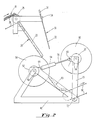
- Feed chute 20 is comprised of planar surface 22, made of hard sheet metal, and mounted at an angle of approximately 55° from the horizontal. The angle is not critical, but 55° has been found to provide good gravity feed of the sheet metal scrap to the pinch rolls 50 and 60.
- the opposite surface of the feed chute 20 is formed by a deflector/sensor gate 30, which comprises a pivoted, counter-weighted hard metal flat surface plate 32, which is pivoted about pivot point 34, and is counter-weighted by suitable counter-weight 36.
- the deflector/sensor gate 30 is mounted so that the pivot point 34 is approximately co-axial with the center of the feed chute conveyor roller 28 and so that when gate 30 is in its normal vertical position (shown in Figure 1), a gap of about five inches exists between the end of gate 30 and the surface 22 of feed chute 20. This gap serves to guide the individual clips of sheet gauge metal scrap material 10 toward pinch rolls 50 and 60.
- the two pinch rolls rotate in opposite clockwise and counterclockwise directions toward each other to provide a positive downward drive of sheet metal clips 10 between the pinch rolls.
- each of the two hydraulic cylinders 54 which interconnect pinch rolls 50 and 60 at opposite ends thereof will exert a compressive force of from approximately 57 kN to approximately 112 kN. At these force levels, the cylinder arms or pistons 56 will move freely to accommodate the varying thicknesses of the sheet gauge metal clips 10 flowing between the rolls.
- the axis of rotation of movable pinch roll 60 is located at an angle of approximately 20° from the horizontal plane including the axis of pinch roll 50, thereby causing the weight of pinch roll 60 to add a component of compressive force to the metal scrap material 10 while providing a positive gravity feed of the metal scrap into the juncture of pinch rolls 50 and 60.
- each hydraulic cylinder 54 has its outer end pivotally mounted by pin 66 to a plate 68 which is rigidly attached to the pivotal arms 70.
- the compression or pinch rolls 50 and 60 and corresponding hydraulic drive motors 52 and 62 for rolls 50 and 60 are rotatably mounted on a suitable rigid steel frame 40.
- Roll 50 and its hydraulic drive motor 52 are rotatably mounted on the frame 40 and each hydraulic cylinder 54 is pivotally mounted to frame 40 by a pivot pin 64.
- Compression roll 60 and its hydraulic drive motor 62 are rotatably mounted between parallel arms 70, and the arms 70 are pivotally mounted at their lower ends to opposing sides of frame 40 by pins 72.
- the rolls or cylinders will automaticlly open and reclose in response to a signal from the deflector/sensor gate 30 if there is a jam of material at the bottom of feed chute 20.
- the feed chute 20 is approximately 1.2 m wide and generally and preferably has a width which is at least 110% of the maximum dimension of the sheet gauge metal scrap clips 10 being fed therethrough.
- the throughput in the feed chute 20 can be of the order of 250 kN per hour, or more.
- the deflector/sensor gate 30 is a partially counterbalanced swinging plate 32, which is almost as wide as the feed chute 20.
- the counterweight 36 conveniently weighs from about 70 percent to about 90 percent, and preferably about 80 percent, of the weight of plate 32. Under normal conditions of continuous feed, individual pieces or clips of scrap will pass freely through the normal 0.13 m spacing at the lower end of gate 30, while overlapping pieces will be deflected for even distribution across the feed chute 20.
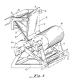
- the gate 30 will be caused by the weight of accumulated material in chute 20 to rotate counterclockwise until it reaches a "relieving position" (shown in Figure 2), where its lower end will be positioned as much as, say, 0.5 m from the surface 22 of feed chute 20, which is four times the normal clearance.
- the exact "relieving position" spacing is a matter of choice.
- An electrical interconnection (not shown) between the deflector/ sensor gate 30 and the hydraulic compression cylinders 54 will activate the hydraulic compression cylinders 54 when the gate 30 is open to the "relieving" position to automatically cause pinch rolls 50 and 60 to open to provide a gap of about 0.6 m between them, as shown in Figure 2, and to permit the scrap material 10 which is backing up to fall clear.
- the gate 30 will return by gravity to a position which is at least 0.25 m from the chute 20, at which time the electrical interconnection (not shown) will cause the hydraulic cylinders 54 to return pinch rolls 50 and 60 to the normal operating position of Figure 1.
- Pinch rolls 50 and 60 are conveniently 1.5 m in diameter. This dimension is determined by the thickness and maximum contortion of the scrap material.
- the width of the rolls 50 and 60 desirably is 0.3 m greater than that of the feed chute, to allow for spreading of the scrap as it is received in the nip of the rolls.
- Pinch rolls 50 and 60 are conveniently fabricated from rolled 20 mm thick mild carbon steel plate with 115 mm diameter shafts, 12.5 mm thick end discs, and two 12.5 mm thick inner discs (not shown) evenly spaced between the end discs for each roll, as determined by roll diameter, width, and total compressive force.
- Each pinch roll is independently driven by an hydraulic motor, respectively designated 52 and 62 for rolls 50 and 60, at a varaible speed which can desirably be adjusted from about 6.5 to about 13 rpm, and which roughly translates to about 30 to about 60 m per minute of roll surface velocity for a 1.5 m diameter roll.
- the roll speed is determined by the average feed material flow rate, and both rolls are set to rotate at the same speed.
- the 40 kW hydraulic motors will exert a minimum torque of 11 kNm at 13 rpm.
- the flow rate of scrap material 10, and the compression force of pinch rolls 50 and 60 are adjusted to provide a bulk loading density in the range from about 6 to about 20, and preferably more than 8, kN/cm3 of the end-product scrap.
- a discharge chute 80 fabricated from hard sheet metal, is rigidly mounted to frame 40 below compression rolls 50 and 60 to receive the substantially flattened product clips exiting from the nip of rolls 50 and 60. These clips fall by gravity through discharge chute 80 and onto discharge conveyor 86, which transports the product clips to a convenient location for further handling.
- discharge chute 80 has a concave longitudinal cross section, so as to deliver the product clips to discharge conveyor 86 without substantial impact with the surface of conveyor 86.
- the process of the invention is a process for taking sheet gauge metal scrap material 10, and converting it into a substantially more planar product having a bulk density in the range of from about 6 to about 20 kN/m3, and preferably at least about 8 kN/m3 and comprising pieces of not more than approximately 1.2 m width by not more than approximately 1.5 m length, and preferably pieces of not more than approximately 0.3 m width by not more than 1 m length.
- individual pieces or clips of sheet gauge metal scrap material are fed between a pair of spaced compression rolls under a combined total force exerted by the two hydraulic cylinders 54 of preferably approximately 225 kN, and are guided so that a relatively uniform feed of sheet gauge metal scrap pieces is fed through the pinch rolls at a linear velocity in the range from about 30 to 60 m per minute.
- the end product is a mass of discrete and substantially flattened pieces of sheet gauge metal scrap material, having a bulk density in the range from about 6 to about 20 kN/cm3.
Landscapes
- Engineering & Computer Science (AREA)
- Mechanical Engineering (AREA)
- Chemical & Material Sciences (AREA)
- Combustion & Propulsion (AREA)
- General Engineering & Computer Science (AREA)
- Manufacture And Refinement Of Metals (AREA)
- Processing Of Solid Wastes (AREA)
- Press Drives And Press Lines (AREA)
Applications Claiming Priority (2)
| Application Number | Priority Date | Filing Date | Title |
|---|---|---|---|
| US856575 | 1986-04-25 | ||
| US06/856,575 US4739641A (en) | 1986-04-25 | 1986-04-25 | Process and apparatus for flattening sheet gauge metal scrap |
Publications (3)
| Publication Number | Publication Date |
|---|---|
| EP0245537A2 true EP0245537A2 (de) | 1987-11-19 |
| EP0245537A3 EP0245537A3 (en) | 1989-02-01 |
| EP0245537B1 EP0245537B1 (de) | 1992-03-25 |
Family
ID=25323985
Family Applications (1)
| Application Number | Title | Priority Date | Filing Date |
|---|---|---|---|
| EP86115644A Expired - Lifetime EP0245537B1 (de) | 1986-04-25 | 1986-11-11 | Verfahren und Vorrichtung zum Glätten von Blechschrott |
Country Status (7)
| Country | Link |
|---|---|
| US (1) | US4739641A (de) |
| EP (1) | EP0245537B1 (de) |
| JP (1) | JP2603718Y2 (de) |
| KR (1) | KR930003538B1 (de) |
| BR (1) | BR8701587A (de) |
| CA (1) | CA1274415A (de) |
| DE (1) | DE3684598D1 (de) |
Cited By (1)
| Publication number | Priority date | Publication date | Assignee | Title |
|---|---|---|---|---|
| WO1999052638A1 (en) * | 1998-04-09 | 1999-10-21 | Syntech Holdings B.V. | Method for debasing coins, devices suitable for carrying out such a method as well as debased coins |
Families Citing this family (6)
| Publication number | Priority date | Publication date | Assignee | Title |
|---|---|---|---|---|
| US5192031A (en) * | 1991-07-05 | 1993-03-09 | Herve Gilbert | Combined trash compactor/conveyor for garbage truck |
| WO2003004125A2 (en) * | 2001-07-05 | 2003-01-16 | Central Manufacturing Company | Launcher for compressible materials and associated process |
| EP2799223A3 (de) * | 2003-07-07 | 2014-12-31 | Ranpak Corp. | Polstermaterialwandler und Verfahren ohne Schneidevorrichtung |
| US6923033B2 (en) * | 2003-10-02 | 2005-08-02 | Soave Enterprises, Llc | Roller system for flattening irregularly shaped, bent pieces of scrap sheet metal |
| US7584530B2 (en) * | 2005-01-12 | 2009-09-08 | Shulman Alvin D | Method and apparatus for compressing scrap metal strip |
| IT201900011238A1 (it) * | 2019-07-09 | 2021-01-09 | Eurven Srl | Compattatore/frantumatore perfezionato |
Family Cites Families (6)
| Publication number | Priority date | Publication date | Assignee | Title |
|---|---|---|---|---|
| US2087806A (en) * | 1936-08-12 | 1937-07-20 | Frederick S Mccune | Method and apparatus for separating metallic articles |
| US2327448A (en) * | 1940-04-12 | 1943-08-24 | Celanese Corp | Speed control for squeeze rolls |
| US2937942A (en) * | 1957-01-23 | 1960-05-24 | American Metal Climax Inc | Process for making metal strip from metal powder |
| FR1376499A (fr) * | 1963-03-19 | 1964-10-31 | Perfectionnements au serrage des cylindres de broyeuses et autres machines à cylindres | |
| US3455136A (en) * | 1966-05-18 | 1969-07-15 | Natalis H Polakowski | Means for surface conditioning metal strip |
| DE3262679D1 (en) * | 1981-09-03 | 1985-04-25 | Bbc Brown Boveri & Cie | Process for manufacturing an article from a heat-resisting alloy |
-
1986
- 1986-04-25 US US06/856,575 patent/US4739641A/en not_active Expired - Lifetime
- 1986-11-11 DE DE8686115644T patent/DE3684598D1/de not_active Expired - Fee Related
- 1986-11-11 EP EP86115644A patent/EP0245537B1/de not_active Expired - Lifetime
-
1987
- 1987-02-18 CA CA000529969A patent/CA1274415A/en not_active Expired - Lifetime
- 1987-03-07 KR KR1019870002043A patent/KR930003538B1/ko not_active Expired - Fee Related
- 1987-04-06 BR BR8701587A patent/BR8701587A/pt unknown
-
1992
- 1992-08-10 JP JP1992061391U patent/JP2603718Y2/ja not_active Expired - Lifetime
Cited By (1)
| Publication number | Priority date | Publication date | Assignee | Title |
|---|---|---|---|---|
| WO1999052638A1 (en) * | 1998-04-09 | 1999-10-21 | Syntech Holdings B.V. | Method for debasing coins, devices suitable for carrying out such a method as well as debased coins |
Also Published As
| Publication number | Publication date |
|---|---|
| EP0245537A3 (en) | 1989-02-01 |
| EP0245537B1 (de) | 1992-03-25 |
| JPH0570788U (ja) | 1993-09-24 |
| CA1274415A (en) | 1990-09-25 |
| KR870009779A (ko) | 1987-11-30 |
| US4739641A (en) | 1988-04-26 |
| JP2603718Y2 (ja) | 2000-03-21 |
| BR8701587A (pt) | 1988-01-26 |
| DE3684598D1 (de) | 1992-04-30 |
| KR930003538B1 (ko) | 1993-05-03 |
Similar Documents
| Publication | Publication Date | Title |
|---|---|---|
| CN114007750B (zh) | 用于粉碎的设备、系统和方法 | |
| JP2010538830A (ja) | 鉱物性および非鉱物性材料の粗粉砕および微粉砕のための方法および装置 | |
| EP0245537A2 (de) | Verfahren und Vorrichtung zum Glätten von Blechschrott | |
| KR900005174B1 (ko) | 재료의 분쇄장치 | |
| US4769211A (en) | Process for compacting iron particles and subsequent breaking apart of the compacted iron band and apparatus for performing this process | |
| US3986864A (en) | Method for briquette breaking | |
| CN118320905A (zh) | 一种石英原矿破碎设备 | |
| US3897183A (en) | Briquette molding apparatus and breaker | |
| CN111457728A (zh) | 一种hrb500e热轧合金钢加工用导送装置 | |
| CN213434718U (zh) | 一种用于矿石加工的破碎机 | |
| JPH0569576B2 (de) | ||
| CN217164577U (zh) | 一种铁精粉生产用粉碎装置 | |
| RU2138332C1 (ru) | Способ измельчения бетона железобетонных конструкций и устройство для его осуществления | |
| JPS62254997A (ja) | シ−トの厚さの金属スクラツプを平らにする方法及び装置 | |
| US2087806A (en) | Method and apparatus for separating metallic articles | |
| CN2397081Y (zh) | 一种螺丝输送机分检机构 | |
| CN210994447U (zh) | 一种对硅料尺寸进行控制的装置 | |
| CN114345895A (zh) | 一种易拉罐破碎生产线 | |
| CN2296765Y (zh) | 一种破碎装置 | |
| CN217968518U (zh) | 一种防卡顿自动压痕机 | |
| CN111330678A (zh) | 一种联合破碎装置及破碎系统 | |
| CN213671114U (zh) | 一种高延性冷轧带肋直条钢筋高速生产线 | |
| CN220715998U (zh) | 一种块状金属粉末用打散装置 | |
| CN112058462A (zh) | 辊式整形机以及石块处理生产线 | |
| CN213044247U (zh) | 一种新型半湿秸秆自动粉碎机 |
Legal Events
| Date | Code | Title | Description |
|---|---|---|---|
| PUAI | Public reference made under article 153(3) epc to a published international application that has entered the european phase |
Free format text: ORIGINAL CODE: 0009012 |
|
| AK | Designated contracting states |
Kind code of ref document: A2 Designated state(s): DE FR GB IT SE |
|
| PUAL | Search report despatched |
Free format text: ORIGINAL CODE: 0009013 |
|
| RHK1 | Main classification (correction) |
Ipc: B30B 3/04 |
|
| AK | Designated contracting states |
Kind code of ref document: A3 Designated state(s): DE FR GB IT SE |
|
| RAP3 | Party data changed (applicant data changed or rights of an application transferred) |
Owner name: CONNELL LIMITED PARTNERSHIP |
|
| 17P | Request for examination filed |
Effective date: 19890728 |
|
| 17Q | First examination report despatched |
Effective date: 19900912 |
|
| GRAA | (expected) grant |
Free format text: ORIGINAL CODE: 0009210 |
|
| AK | Designated contracting states |
Kind code of ref document: B1 Designated state(s): DE FR GB IT SE |
|
| REF | Corresponds to: |
Ref document number: 3684598 Country of ref document: DE Date of ref document: 19920430 |
|
| ITF | It: translation for a ep patent filed | ||
| ET | Fr: translation filed | ||
| PLBE | No opposition filed within time limit |
Free format text: ORIGINAL CODE: 0009261 |
|
| STAA | Information on the status of an ep patent application or granted ep patent |
Free format text: STATUS: NO OPPOSITION FILED WITHIN TIME LIMIT |
|
| 26N | No opposition filed | ||
| PGFP | Annual fee paid to national office [announced via postgrant information from national office to epo] |
Ref country code: SE Payment date: 19931004 Year of fee payment: 8 |
|
| PG25 | Lapsed in a contracting state [announced via postgrant information from national office to epo] |
Ref country code: SE Effective date: 19941112 |
|
| EAL | Se: european patent in force in sweden |
Ref document number: 86115644.6 |
|
| EUG | Se: european patent has lapsed |
Ref document number: 86115644.6 |
|
| PGFP | Annual fee paid to national office [announced via postgrant information from national office to epo] |
Ref country code: FR Payment date: 19970929 Year of fee payment: 12 |
|
| PGFP | Annual fee paid to national office [announced via postgrant information from national office to epo] |
Ref country code: DE Payment date: 19980127 Year of fee payment: 12 |
|
| PGFP | Annual fee paid to national office [announced via postgrant information from national office to epo] |
Ref country code: GB Payment date: 19981028 Year of fee payment: 13 |
|
| PG25 | Lapsed in a contracting state [announced via postgrant information from national office to epo] |
Ref country code: FR Free format text: LAPSE BECAUSE OF NON-PAYMENT OF DUE FEES Effective date: 19990730 |
|
| REG | Reference to a national code |
Ref country code: FR Ref legal event code: ST |
|
| PG25 | Lapsed in a contracting state [announced via postgrant information from national office to epo] |
Ref country code: DE Free format text: LAPSE BECAUSE OF NON-PAYMENT OF DUE FEES Effective date: 19990901 |
|
| PG25 | Lapsed in a contracting state [announced via postgrant information from national office to epo] |
Ref country code: GB Free format text: LAPSE BECAUSE OF NON-PAYMENT OF DUE FEES Effective date: 19991111 |
|
| GBPC | Gb: european patent ceased through non-payment of renewal fee |
Effective date: 19991111 |
|
| PG25 | Lapsed in a contracting state [announced via postgrant information from national office to epo] |
Ref country code: IT Free format text: LAPSE BECAUSE OF NON-PAYMENT OF DUE FEES;WARNING: LAPSES OF ITALIAN PATENTS WITH EFFECTIVE DATE BEFORE 2007 MAY HAVE OCCURRED AT ANY TIME BEFORE 2007. THE CORRECT EFFECTIVE DATE MAY BE DIFFERENT FROM THE ONE RECORDED. Effective date: 20051111 |