EP0245519B1 - Fernsehsynchronisierungssystem - Google Patents
Fernsehsynchronisierungssystem Download PDFInfo
- Publication number
- EP0245519B1 EP0245519B1 EP86906933A EP86906933A EP0245519B1 EP 0245519 B1 EP0245519 B1 EP 0245519B1 EP 86906933 A EP86906933 A EP 86906933A EP 86906933 A EP86906933 A EP 86906933A EP 0245519 B1 EP0245519 B1 EP 0245519B1
- Authority
- EP
- European Patent Office
- Prior art keywords
- sync signal
- pulse
- signal
- television
- horizontal
- Prior art date
- Legal status (The legal status is an assumption and is not a legal conclusion. Google has not performed a legal analysis and makes no representation as to the accuracy of the status listed.)
- Expired - Lifetime
Links
Images




Classifications
-
- H—ELECTRICITY
- H04—ELECTRIC COMMUNICATION TECHNIQUE
- H04N—PICTORIAL COMMUNICATION, e.g. TELEVISION
- H04N5/00—Details of television systems
- H04N5/04—Synchronising
- H04N5/06—Generation of synchronising signals
- H04N5/067—Arrangements or circuits at the transmitter end
Definitions
- the present invention relates to a television synchronization system and more particularly to a television synchronization system in which a sync signal has bipolar pulses, i.e., positive and negative polarity pulses which are symmetrical, so that a reproduced sync signal synchronously separated from a transmitted television signal has an improved accuracy of phase error.
- a sync signal has bipolar pulses, i.e., positive and negative polarity pulses which are symmetrical, so that a reproduced sync signal synchronously separated from a transmitted television signal has an improved accuracy of phase error.
- a television sync signal generally consists of a negative polarity pulse only.
- a reference phase of a sync signal which is synchronously separated and reproduced from a transmitted television signal varies due to variations in frequency characteristics of a transmission line and variations in amplitude.
- Figs. 1A and 1B show waveforms of a horizontal sync signal which is used in a conventional television system and is reproduced after transmission.
- Fig. 1A the normal horizontal sync signal is indicated by the solid line and the intersection 101A of the horizontal sync signal with the reference level indicates the reference phase.
- the waveform shown by the broken-line is the horizontal sync signal distorted by the transmission line.
- the intersection 102A of the distorted horizontal sync signal with the reference level indicates a phase which is different from the reference phase.
- the horizontal sync signal which is reproduced from the above-described normal horizontal sync signal is indicated by the solid line
- the horizontal sync signal which is reproduced from the distorted horizontal sync signal is indicated by the broken-line.
- the reproduced phase is shifted due to the distortion and this shift varies depending on changes of the transmission line characteristics.
- Figs. 2A, 2B and 2C are waveforms showing a vertical sync portion of the composite sync signal used in the conventional television system.
- Fig. 2A is the waveform of the composite sync signal in the first field
- Fig. 2B is the waveform of the composite sync signal in the second field.
- an integrator for instance, can be used.
- Fig. 2C shows an integrated waveform of a signal obtained by an integration circuit.
- the solid line indicates the integrated waveform of the first field, while the broken-line indicates the integrated waveform in the second field.
- the vertical sync signal is reproduced in different phase as indicated by the intersections 201 and 202 with the reference level in Fig. 2C.
- a television system which uses a line synchronising pulse starting with a blacker-than-black pulse rising sharply to a peak-white pulse which is followed by a pulse at black reference level.
- This synchronising pulse thus provides a front porch which is constituted by the sharp rise from blacker-than-black to peak-white as well as peak-white and black reference levels.
- FR-A-1 007 940 describes a television system in which bipolar pulses can be used as control signals for the receiver.
- a first aspect of a television synchronization system in accordance with the present invention is characterized by the features of claim 1.
- the means for forming the horizontal sync signal can form a horizontal sync signal in which amplitudes of waveforms in front of and in the rear of said phase reference point are equal in their absolute values and are opposite in their polarities.
- the horizontal sync signal forming means can form a horizontal sync signal whose waveforms in front of and in a rear of the phase reference point are symmetrical with respect to the phase reference point.
- the horizontal sync signal forming means can form a horizontal sync signal which includes a negative polarity pulse and a positive polarity pulse which are disposed closely and have the same pulse amplitude and the same pulse width.
- the horizontal sync signal forming means can form the horizontal zync signal in the form of a bipolar signal including a front porch, the negative polarity pulse, the positive polarity pulse and a back porch.
- the vertical sync signal generating means can form a vertical sync signal including the positive polarity pulse, the back porch, the wide-pulse-width negative polarity pulse and the negative polarity pulse.
- the positive and negative polarity pulses can have a pulse amplitude of 300 ⁇ 6 mV and a pulse width of 0.59 ⁇ 0.03 ⁇ sec.
- the wide-pulse-width negative polarity pulse can have a pulse width of 11.86 ⁇ 0.05 ⁇ sec.
- a second aspect of a television synchronization system in accordance with the present invention is characterized by the features of claim 9.
- the television synchronization system in accordance with the present invention can be constructed by the provision of means for generating clock signals; first counting means for counting the clock signals from said clock signal generating means to generate a first count output every one horizontal scanning period; second counting means for counting the number of the horizontal scanning period corresponding to said first count output from said first counting means; storage means for storing horizontal sync signal information corresponding to a waveform of said horizontal sync signal in advance within one horizontal scanning period; output means for deriving from said storage means the horizontal sync signal information corresponding to the number of the horizontal scanning period obtained from said second counting means; and conversion means for accomplishing D/A conversion of an output from said output means to generate television horizontal and vertical sync signals.
- the above-described television synchronization system can comprise: means for receiving a television signal; gate pulse generating means for detecting said negative polarity pulse from a sync signal included in the received television signal to generate a gate pulse for extracting a position of said phase reference point at which there is a conversion from said negative polarity pulse into said positive polarity pulse; clamping means for clamping said received television signal at a reference level of said sync signal; comparison means for comparing the reference level derived from said clamping means with the reference level of said sync signal; gate means for detecting said position of said phase reference point in response to said gate pulse derived from said gate pulse generating means and a comparison output from said comparison means; and means for reproducing the television sync signal in accordance with the detected position of said phase reference point.
- the reference level of said television sync signals can be set at a level determined by sampling the television signal derived from said clamping means by a sampling pulse produced in one horizontal scanning period within a vertical sync blanking period.
- a television synchronization method according to the invention is characterized by the features of claim 13.
- amplitudes of the waveforms of the horizontal sync signal in front of and in the rear of the phase reference point can be equal in their absolute values and can be opposite in their polarities.
- the waveforms of the horizontal sync signal in front of and in the rear of the phase reference point can be symmetrical with respect to the phase reference point.
- the horizontal sync signal can include a negative polarity pulse and a positive polarity pulse which are disposed closely and have the same amplitude and the same pulse width.
- the horizontal sync signal can be in the form of a bipolar signal including a front porch, the negative polarity pulse, the positive polarity pulse and a back porch.
- the vertical sync signal can be in the form of a composite signal including the positive polarity pulse, the back porch, the negative pulse having a wide pulse width, the front porch and the negative polarity pulse.
- the positive and negative polarity pulses can have a pulse amplitude of 300 ⁇ 6 mV and a pulse width of 0.59 ⁇ 0.03 ⁇ sec.
- the wide-pulse-width negative polarity pulse can have a pulse width of 11.86 ⁇ 0.05 ⁇ sec.
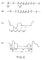
- Figs. 3A, 3B, 3C and 3D are waveforms showing a fundamental arrangement of a composite sync signal in accordance with the present invention.
- Figs. 3A and 3B are waveforms showing a composite sync signal corresponding to a vertical blanking period of the first and second fields, respectively, and Figs. 3C and 3D are waveforms showing in detail horizontal and vertical sync pulses corresponding to time intervals 301 and 302, respectively, shown by the broken-lines in Fig. 3A.
- one horizontal sync signal consists of a pair of negative and positive polarity pulses.
- an interval 303 is referred to as a front porch which is used to separate the picture signal from the sync signal.
- Intervals 304 and 305 indicate a negative polarity pulse and a positive polarity pulse, respectively, which constitute a horizontal sync pulse.
- An interval 306 is used as a clamping position or a sampling position of a reference level. The interval 306 also serves as a back porch for separating the sync signal from the picture signal.
- an interval 307 indicates a portion of a vertical sync pulse and an interval 308 serves to connect the trailing edge of the interval 307 to the front porch of the next sync signal.
- An interval 309 denotes a negative polarity pulse and corresponds to the interval 304.
- the intervals 305-309 correspond to one half (1/2) of the horizontal scanning period.
- pulse widths 304 and 305 of the positive and negative polarity pulses are equal to each other and their pulse amplitudes are also equal to each other.
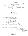
- Fig. 4 a position of a reproduced phase in an embodiment of a horizontal sync pulse in accordance with the present invention will be described.
- the solid line indicates a normal waveform, while the broken-line indicates a distorted (linear distortion) waveform.
- Figs. 5A, 5B, 5C and 5D are waveforms used to explain an operation of vertical synchronization in accordance with the present invention.
- Figs. 5A and 5B are waveforms showing the composite sync signal in the vertical blanking intervals in the first and second fields, respectively.
- Fig. 5C indicates, in an enlarged form, a waveform obtained by the superposition of intervals 501 and 502 shown in Figs. 5A and 5B.
- the solid line indicates the signal in the first field, while the broken-line indicates the signal in the second field,
- Fig. 5D shows an integrated waveform obtained by integrating the signal shown in Fig. 5C.
- the horizontal sync signal has a waveform which is point-symmetrical and which consists of a positive polarity pulse and a negative polarity pulse, so that the waveform obtained by the integration of the horizontal sync signal always becomes zero before and after the horizontal sync pulse.
- the integrated output has the same waveform regardless of the first or second field. More specially, the waveforms of the vertical sync pulses in the vertical blanking intervals are the same in both the fields, so that the integrated outputs of the vertical sync pulses have the same waveform. Therefore, when a position 503 at which the integrated waveform intersects the. reference level is selected as a reference of a reproduced vertical sync phase, the vertical sync signals are reproduced with the same phase in both the first and second fields,
- the average pulse levels (APL) are not zero. Therefore, when the reference level varies, a alight variation in reproduced phase of the vertical sync signal occures.
- Figs. 6A and 6B show the composite sync signal corresponding to a vertical blanking period of the first and second fields, respectively.
- the reference level is set to zero potential. Then, there is no influence at all caused by the variation in reference level.
- the pulse train consisting only of the negative pulses derived from the waveform is similar in waveform to the conventional composite sync signal. Therefore, in a system in which a slight error in a reproduced phase is allowed, like in a CRT monitor, the sync signal can be separated by a conventional amplitude separation circuit.
- Figs. 7A and 7B are waveforms showing a signal arrangement in a case where there are 1125 scanning lines and the 2: 1 interlaced scanning is carried out, as an embodiment of a television synchronization system in accordance with the present invention.
- Figs. 7A and 7B indicate waveforms of the sync signals mainly in the vertical blanking intervals in the first and second fields, respectively.
- Figs. 7A and 7B the numerals indicate the number of horizontal scanning line and H expresses one horizontal scanning period.
- a vertical blanking period is provided with 45H in total and consists of 5H in the first field or 5.5H in the second field before the vertical sync pulse portion, a 5H vertical sync pulse portion and 35H in the first field or 34.5H in the second field following the vertical sync pulse portion.
- Fig. 8 is a block diagram showing an arrangement of one embodiment of the present invention for generating the television sync signals as shown in Fig. 7.
- 801 denotes an oscillator for generating clock pulses.
- 802 is an H counter for generating one output every horizontal scanning period (1H).
- 803 is a V counter for counting one frame period.
- HROM 804 is an HROM which, as will be described in detail hereinafter, stores different waveform information concerning the waveform information in one horizontal scanning period (1H) at a predetermined horizontal scanning position within one frame.
- D/A converter 806 is a D/A converter which accomplishes digital-to-analog conversion of the output date derived from HROM 804 to generate the composite sync signal.
- VROM 805 denotes a VROM which, as will be described in more detail with reference to Fig. 9, stores the information for switching the waveforms within one horizontal scanning period (1H) in response to the horizontal scanning line number in one frame which is counted by the V counter 803, so that in response to the stored information, the waveform information in the HROM 804 is switched in accordance with the horizontal scanning position as shown in Fig. 9.
- a sync signal generator for generating the composite sync signal used in the 2: 1 interlaced scanning system in case of 1125 horizontal scanning lines, as mentioned above, will be described in detail.
- the oscillator 801 generates the clock signal at 4.05 MHz.
- the H counter 802 counts the clock signal during one horizontal scanning period (1H).
- the horizontal scanning frequency fh is 33.75 KHz, so that the number of clock pulses during one horizontal scanning period (1H) becomes 120 obtained by dividing 4.05 MHz by 33.75 KHz.
- the H counter 802 carries out frequency division in such a manner that one pulse is generated for every 120 clock pulses and accordingly the output pulse is generated for every one horizontal scanning period (1H).
- the V counter 803 counts the output pulses from the H counter 802 and accomplishes frequency division in such a way that one output pulse is generated for every one frame period.
- the HROM 804 receives both the output pulses from the H counter 802 and the output digital data from the VROM 805, then outputs digital data corresponding to the waveform in a predetermined 1H period with respect to the scanning line position determined by the V counter 803.
- the output data from the HROM 804 consists of two-bit data having an upper bit and a lower bit, so that the three levels "-1, "0" and "+1" of the positive and negative polarity pulses can be expressed by the following correspondence, for instance:
- the HROM output consisting of one of the above-described combinations of two bits is supplied to the D/A converter 806 and is converted into the analog signal, so that a sync signal having a waveform in the form of analog signal formed by three levels "-1", "0" and "+1" is generated.
- the VROM 805 is used to reduce a storage capacity of the HROM 804. That is, when the same signal waveform is used for every horizontal scanning period (1H) in all of one frame, it is sufficient that one type of the signal waveform is stored in the HROM 804, so that an arrangement of the HROM 804 can be made simple. However, in practice, in order to generate the vertical sync signal for 2: 1 interlaced scanning system, the waveforms in respective 1H periods at predetermined scanning lines in each field are different.
- the V counter 803 counts the number of the horizontal scanning lines in one frame so as to discriminate the waveforms of the sync signal in 1H. That is, the information for switching the waveforms in 1H in response to the horizontal scanning line number is stored in the VROM 805.
- the three-bit output derived from the VROM 805 is utilized.
- the two-bit output derived from the HROM 804 may have various formats in addition to that described above with reference to Fig. 9, depending upon characteristics of D/A converters used for D/A conversion of the two-bit data.
- Fig. 10 is a block diagram showing one embodiment of a circuit for separating the sync signal generated in accordance with the present invention.
- reference numeral 101 denotes an input terminal for receiving a television signal (A), the pedestal level of which is used as a reference level.
- Reference numeral 102 denotes a binary separation circuit which generates binary pulses from the negative pulses of the composite sync signal.
- Reference numeral 103 denotes a pedestal clamping circuit for clamping the pedestal of the television signal derived from the input terminal 101 in response to a reference level (pedestal) extracted by the clamping pulse (C) which in turn is derived from the binary separation circuit 102.
- 104 denotes a comparator for comparing the television signal whose pedestal is clamped by the clamping circuit 103, with the reference level to obtain a comparator output (D).
- Reference numeral 105 denotes a gate circuit for extracting the comparator output (D) during the gate pulse (B) to obtain a timing pulse (E).
- Reference numeral 106 is a logic circuit for generating the horizontal and vertical sync signals based on the precision phase pulses delivered from the gate circuit 105.
- Reference numeral 107 is an output terminal.
- the input terminal 101 receives the television signal (A) which includes the tri-level bipolar sync signal.
- the binary separation circuit 102 detects only the negative polarity pulses based on the threshold level for binary circuit, thereby extracting-the negative polarity pulse of the horizontal sync signal as shown in Fig. 11A. Then, as shown in Figs. 11B and 11C, the gate pulse (B) and the clamping pulse (C) are generated.
- the binary separation circuit 102 per se can be easily constructed from the circuits used in the conventional television system. Furthermore, the purpose of the binary separation can be satisfactorily obtained by the degree of precision obtained by such a construction of the binary separation circuit 102.
- the clamping pulse (C) derived from the binary separation circuit 102 is applied to the pedestal clamping circuit 103.
- the pedestal of the television signal (A) derived from the input terminal 101 is clamped to the reference level and furthermore the output from the pedestal clamping circuit 103 is shaped into a binary logic signal by the comparator 104.
- the pedestal level is used as a comparison reference level and the horizontal sync signal in the television signal whose pedestal is clamped is compared with the pedestal level.
- the waveform of an output signal (D) from the comparator 104 is shown in Fig. 11D.
- the gate circuit 105 can extract a pulse output (E) at the timing that the tri-level bipolar sync signal crosses the pedestal level.
- the pulse output (E) at this timing will be referred to as a precision phase pulse hereinafter in this specification.
- Fig. 11E shows the waveform of this pulse and its timing position.
- the timing position can be set as a reference point which is hardly adversely affected by the characteristics of a transmission line.
- the logic circuit 106 can generate desired horizontal and vertical sync signals.
- the logic circuit 106 per se can be easily constructed by combining binary logic circuits practically used for reproducing the conventional television sync signal.
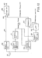
- Fig. 12 is a block diagram showing another embodiment of a circuit arrangement for separating the sync signal formed in accordance with the present invention.
- reference numeral 108 denotes a sample-and-bold circuit; 109, a low pass filter (LPF); 110, a vertical sync separation circuit; and 111, a sampling circuit.
- LPF low pass filter
- Figs. 13A and 13B show waveforms used to explain the mode of operation of the embodiment shown in Fig. 12.
- the performance of the sync separation circuit is clearly dependent on a degree of precision of the pedestal clamping. Therefore, it is preferable that a feedback clamping circuit is used to clamp the pedestal.
- the vertical sync separation circuit 110 and the sampling circuit 111 extract 1H in the vertical blanking period and furthermore, as shown in Fig. 13B, a sampling pulse (G) is generated at a timing in a portion which is not adversely affected by the waveform distortion of the sync pulse within 1H period.
- the pedestal clamping circuit 103 the pedestal of the television signal (A) received at the input terminal 101 is clamped to the reference level.
- sample-and-hold circuit 108 a portion in the vertical blanking period of the television signal which is clamped in the clamping circuit 103 is sampled by the sampling pulse (G) and the pedestal level thus sampled is held.
- the output of the pedestal level thus sampled and held is applied to the low-pass filter 109 to obtain a reference level signal (H) which in turn is applied to the comparator 104.
- the comparator 104 like in the embodiment described above with reference to Fig. 10, the clamped television signal derived from the clamping circuit 103 is compared with the reference level signal (H) so that the comparator output (D) is obtained as shown in Fig. 11D.
- the comparator output (D) a portion corresponding to the timing of the gate pulse (B) is extracted to obtain the precision phase pulse (E).
- the need for correctly separating the sync signal is limited to a case in which the influences of the waveform distortion of the sync signal disappear within a short period of time.
- the pedestal level can be correctly detected by utilizing the sample-and-hold circuit 108 in the arrangement of the embodiment as shown in Fig. 12.
- the comparator 104 can extract the above-described precision phase timing by using the detected pedestal level as a reference level.
- an accuracy of a reproduced phase of a television synchronization signal reproduced from a transmitted television signal is improved and influences due to linear distortion of the waveform of the sync signal caused in the transmission line or the like are eliminated.
- the television sync signal in accordance with the present invention a reproduced phase is correct, so that the television sync signal is advantageously used as a synchronization signal for a transmission system (TCI system) in which television signals are compressed in the direction of the time axis and then multiplexed.
- TCI system transmission system
- the television synchronization signal in accordance with the present invention can be used as a phase control signal for adjusting a transmission delay time in each transmission line.
Landscapes
- Engineering & Computer Science (AREA)
- Multimedia (AREA)
- Signal Processing (AREA)
- Synchronizing For Television (AREA)
- Television Systems (AREA)
Claims (20)
eine Einrichtung (801-806) zum Formen eines Zeilensynchronsignals mit einer Periode, die gleich einer Zeilenabtastperiode ist,
eine Einrichtung (801-806) zum Formen eines Halbbildsynchronsignals, das eine Periode hat, die gleich einer Halbbildperiode ist, und das ein bipolares Signal mit einem positiven und einem negativen Impuls enthält,
eine Einrichtung zum Formen eines Fernsehsynchronsignals aus einer Anordnung der Zeilen- und Halbbildsynchronsignale und
eine Einrichtung zum Einstellen eines Phasenbezugpunkts des Zeilensynchronsignals auf einen mit einem Bezugspegel übereinstimmenden Punkt enthält,
dadurch gekennzeichnet, daß eine Einrichtung derart vorgesehen ist, daß das von der Halbbildsynchronsignal-Formungseinrichtung (801-806) geformte Halbbildsynchronsignal hinter dem bipolaren Signal einen Impuls (307) negativer Polarität enthält, dessen Impulsbreite größer als die Impulsbreite der Impulse des bipolaren Signals ist.
eine Einrichtung (801-806) zum Formen eines Zeilensynchronsignals, das eine Periode hat, die gleich einer Zeilenabtastperiode ist, und das ein bipolares Signal mit einem positiven und einem negativen Impuls enthält, eine Einrichtung (801-806) zum Formen eines Halbbildsynchronsignals mit einer Periode, die gleich einer Halbbildperiode ist, und
eine Einrichtung zum Formen eines Fernsehsynchronsignals aus einer Anordnung der Zeilen- und Halbbildsynchronsignale enthält,
dadurch gekennzeichnet, daß eine Einrichtung derart vorgesehen ist, daß das bipolare Signal des Zeilensynchronsignals einen Impuls (304) negativer Polarität vor einem Phasenbezugpunkt und einen Impuls (305) positiver Polarität hinter dem Phasenbezugpunkt hat, und daß eine weitere Einrichtung für das Anordnen eines zusammengesetzten Signals innerhalb einer auf einen Impuls (304) negativer Polarität folgenden halben Zeilenabtastperiode vorgesehen ist, welches einen Impuls (305) positiver Polarität, eine hintere Schwarzschulter (306), einen Impuls (307) negativer Polarität mit einer Impulsbreite, die größer als die Impulsbreite der Impulse des bipolaren Signals ist, eine vordere Schwarzschulter (308) und einen Impuls (309) negativer Polarität enthält, um aus dem zusammengesetzten Signal das Halbbildsynchronsignal zu bilden.
eine Einrichtung (801) zum Erzeugen eines Taktsignals,
eine erste Zähleinrichtung (802) zum Zählen des Taktsignals aus der Taktsignal-Erzeugungseinrichtung (801) für das Erzeugen eines ersten Zählausgangssignals je Zeilenabtastperiode
eine zweite Zähleinrichtung (803) zum Zählen der Nummer der dem ersten Zählausgangssignal aus der ersten Zähleinrichtung (802) entsprechenden Zeilenabtastperiode,
eine Speichereinrichtung (804) zum Speichern der einer Kurvenform des Halbbildsynchronsignals entsprechenden Zeilensynchronsignal-Information im voraus innerhalb einer Horizontalabtastperiode,
eine Ausgabeeinrichtung zum Abrufen der Zeilensynchronsignal-Information, die der aus der zweiten Zähleinrichtung (802) stammenden Nummer der Zeilenabtastperiode entspricht, aus der Speichereinrichtung (804) und
eine Wandlereinrichtung (806) zur D/A/Umsetzung eines Ausgangssignals der Ausgabeeinrichtung für das Erzeugen der Fernseh- Zeilen- und Halbbildsynchronsignale.
eine Einrichtung (101) zum Empfangen eines Fernsehsignals,
eine Torimpulserzeugungseinrichtung (102) zum Erfassen des Impulses negativer Polarität aus einem in dem empfangenen Fernsehsignal enthaltenen Synchronsignal für das Erzeugen eines Torimpulses zum Herausgreifen einer Stelle des Phasenbezugpunkts, an dem eine Umkehr von dem Impuls negativer Polarität auf den Impuls positiver Polarität auftritt,
eine Halteeinrichtung (103) zum Festhalten des empfangenen Fernsehsignals auf einem Bezugspegel des Synchronsignals,
eine Vergleichseinrichtung (104) zum Vergleichen des aus der Halteeinrichtung hergeleiteten Bezugspegels mit dem Bezugspegel des Synchronsignals,
eine Toreinrichtung (105) zum Erfassen der Stelle des Phasenbezugpunkts im Ansprechen auf den aus der Torimpulserzeugungseinrichtung hergeleiteten Torimpuls und auf ein aus der Vergleichseinrichtung hergeleitetes Vergleichsausgangssignal und
eine Einrichtung (106) zum Wiedergeben des Fernsehsynchronsignals in Übereinstimmung mit der erfaßten Stelle des Phasenbezugspunkts.
das Halbbildsynchronsignal einen auf das bipolare Signal folgenden Impuls (307) negativer Polarität mit einer großen Impulsbreite enthält, die größer als die Impulsbreite der Impulse des bipolaren Signals ist.
Applications Claiming Priority (2)
| Application Number | Priority Date | Filing Date | Title |
|---|---|---|---|
| JP256804/85 | 1985-11-18 | ||
| JP25680485 | 1985-11-18 |
Publications (3)
| Publication Number | Publication Date |
|---|---|
| EP0245519A1 EP0245519A1 (de) | 1987-11-19 |
| EP0245519A4 EP0245519A4 (de) | 1988-05-02 |
| EP0245519B1 true EP0245519B1 (de) | 1991-07-17 |
Family
ID=17297668
Family Applications (1)
| Application Number | Title | Priority Date | Filing Date |
|---|---|---|---|
| EP86906933A Expired - Lifetime EP0245519B1 (de) | 1985-11-18 | 1986-11-17 | Fernsehsynchronisierungssystem |
Country Status (3)
| Country | Link |
|---|---|
| US (1) | US4864400A (de) |
| EP (1) | EP0245519B1 (de) |
| WO (1) | WO1987003155A1 (de) |
Families Citing this family (7)
| Publication number | Priority date | Publication date | Assignee | Title |
|---|---|---|---|---|
| DE3809075A1 (de) * | 1988-03-18 | 1989-09-28 | Philips Patentverwaltung | Steuersignalgenerator fuer die verarbeitung eines videosignales |
| US5142575A (en) * | 1988-04-29 | 1992-08-25 | Scientific-Atlanta, Inc. | Method and apparatus for improving video scrambling and employing split sync pulses |
| DE3834865C2 (de) * | 1988-10-13 | 1995-11-16 | Broadcast Television Syst | Verfahren und Schaltung zur Ableitung von H- und V-frequenten Synchronimpulsen |
| JP3021966B2 (ja) * | 1992-06-03 | 2000-03-15 | 松下電器産業株式会社 | 同期信号発生回路および映像信号処理装置 |
| US5583562A (en) * | 1993-12-03 | 1996-12-10 | Scientific-Atlanta, Inc. | System and method for transmitting a plurality of digital services including imaging services |
| KR0179844B1 (ko) * | 1995-10-06 | 1999-05-01 | 문정환 | 티브이의 화면 모서리 부분의 밝기 조정회로 |
| US6559891B1 (en) * | 2000-08-15 | 2003-05-06 | Sony Corporation | Method and apparatus to generate tri-level HDTV synchronization pulses |
Family Cites Families (5)
| Publication number | Priority date | Publication date | Assignee | Title |
|---|---|---|---|---|
| NL67101C (de) * | 1948-04-17 | |||
| GB887532A (en) * | 1959-05-28 | 1962-01-17 | British Broadcasting Corp | Improvements relating to television systems |
| JPS52117380A (en) * | 1976-03-29 | 1977-10-01 | Toyo Ink Mfg Co | Process for manufacturing laminated object |
| US4316219A (en) * | 1980-07-17 | 1982-02-16 | Rca Corporation | Synchronizing circuit adaptable for various TV standards |
| JPH112770A (ja) * | 1997-06-12 | 1999-01-06 | Matsushita Electric Ind Co Ltd | 水平光走査画像記録装置 |
-
1986
- 1986-11-17 US US07/066,482 patent/US4864400A/en not_active Expired - Lifetime
- 1986-11-17 WO PCT/JP1986/000587 patent/WO1987003155A1/ja not_active Ceased
- 1986-11-17 EP EP86906933A patent/EP0245519B1/de not_active Expired - Lifetime
Also Published As
| Publication number | Publication date |
|---|---|
| EP0245519A4 (de) | 1988-05-02 |
| US4864400A (en) | 1989-09-05 |
| EP0245519A1 (de) | 1987-11-19 |
| WO1987003155A1 (fr) | 1987-05-21 |
Similar Documents
| Publication | Publication Date | Title |
|---|---|---|
| KR100307979B1 (ko) | 보조비디오데이타슬라이서 | |
| USRE40411E1 (en) | Synchronizing signal separating apparatus and method | |
| US5280356A (en) | Clamp circuit for clamping video signal including synchronizing signal at a prescribed potential | |
| EP0245519B1 (de) | Fernsehsynchronisierungssystem | |
| US4095259A (en) | Video signal converting system having quantization noise reduction | |
| CA1287682C (en) | Clamping circuit for clamping video signal | |
| CA1189960A (en) | Television signal amplitude detection circuit | |
| US4723164A (en) | Tri-state sync technique | |
| US4215371A (en) | Front porch clamping circuit | |
| EP0391643B1 (de) | Klemmschaltung für ein Digitalsignal | |
| US4491870A (en) | Digital sync separator | |
| KR910006292B1 (ko) | 텔레비젼 동기방식 | |
| JP2620540B2 (ja) | テレビジョン同期信号分離回路 | |
| US4829377A (en) | Horizontal synchronization, clock synchronization, D. C. restoration and gain control scheme for an analog TV system | |
| US3941920A (en) | Receiver for a still picture broadcasting signal | |
| JPH0828831B2 (ja) | テレビジョン同期信号発生回路 | |
| JP2514183B2 (ja) | 位相検出回路 | |
| US4910587A (en) | Information signal processing apparatus | |
| JPWO1987003155A1 (ja) | テレビジョン同期信号発生回路 | |
| JP2572975B2 (ja) | 直流分再生回路 | |
| JPS6151831B2 (de) | ||
| JPH0339988Y2 (de) | ||
| JP3232594B2 (ja) | 同期回路 | |
| JP2568055Y2 (ja) | テレビジョン信号のクランプ装置 | |
| JPH04355569A (ja) | 同期信号処理装置 |
Legal Events
| Date | Code | Title | Description |
|---|---|---|---|
| PUAI | Public reference made under article 153(3) epc to a published international application that has entered the european phase |
Free format text: ORIGINAL CODE: 0009012 |
|
| 17P | Request for examination filed |
Effective date: 19870603 |
|
| AK | Designated contracting states |
Kind code of ref document: A1 Designated state(s): DE FR GB NL SE |
|
| A4 | Supplementary search report drawn up and despatched |
Effective date: 19880502 |
|
| 17Q | First examination report despatched |
Effective date: 19890811 |
|
| GRAA | (expected) grant |
Free format text: ORIGINAL CODE: 0009210 |
|
| AK | Designated contracting states |
Kind code of ref document: B1 Designated state(s): DE FR GB NL SE |
|
| REF | Corresponds to: |
Ref document number: 3680330 Country of ref document: DE Date of ref document: 19910822 |
|
| ET | Fr: translation filed | ||
| PLBE | No opposition filed within time limit |
Free format text: ORIGINAL CODE: 0009261 |
|
| STAA | Information on the status of an ep patent application or granted ep patent |
Free format text: STATUS: NO OPPOSITION FILED WITHIN TIME LIMIT |
|
| 26N | No opposition filed | ||
| REG | Reference to a national code |
Ref country code: GB Ref legal event code: 746 Effective date: 19940722 |
|
| EAL | Se: european patent in force in sweden |
Ref document number: 86906933.6 |
|
| REG | Reference to a national code |
Ref country code: GB Ref legal event code: 747D |
|
| REG | Reference to a national code |
Ref country code: GB Ref legal event code: 747C |
|
| REG | Reference to a national code |
Ref country code: GB Ref legal event code: IF02 |
|
| PGFP | Annual fee paid to national office [announced via postgrant information from national office to epo] |
Ref country code: SE Payment date: 20051107 Year of fee payment: 20 |
|
| PGFP | Annual fee paid to national office [announced via postgrant information from national office to epo] |
Ref country code: FR Payment date: 20051108 Year of fee payment: 20 |
|
| PGFP | Annual fee paid to national office [announced via postgrant information from national office to epo] |
Ref country code: DE Payment date: 20051110 Year of fee payment: 20 |
|
| PGFP | Annual fee paid to national office [announced via postgrant information from national office to epo] |
Ref country code: NL Payment date: 20051115 Year of fee payment: 20 |
|
| PGFP | Annual fee paid to national office [announced via postgrant information from national office to epo] |
Ref country code: GB Payment date: 20051116 Year of fee payment: 20 |
|
| PG25 | Lapsed in a contracting state [announced via postgrant information from national office to epo] |
Ref country code: GB Free format text: LAPSE BECAUSE OF EXPIRATION OF PROTECTION Effective date: 20061116 |
|
| PG25 | Lapsed in a contracting state [announced via postgrant information from national office to epo] |
Ref country code: NL Free format text: LAPSE BECAUSE OF EXPIRATION OF PROTECTION Effective date: 20061117 |
|
| REG | Reference to a national code |
Ref country code: GB Ref legal event code: PE20 |
|
| NLV7 | Nl: ceased due to reaching the maximum lifetime of a patent |
Effective date: 20061117 |
|
| EUG | Se: european patent has lapsed |