EP0245220B1 - A suspension for motored and unmotored wheels of vehicles - Google Patents
A suspension for motored and unmotored wheels of vehicles Download PDFInfo
- Publication number
- EP0245220B1 EP0245220B1 EP87830156A EP87830156A EP0245220B1 EP 0245220 B1 EP0245220 B1 EP 0245220B1 EP 87830156 A EP87830156 A EP 87830156A EP 87830156 A EP87830156 A EP 87830156A EP 0245220 B1 EP0245220 B1 EP 0245220B1
- Authority
- EP
- European Patent Office
- Prior art keywords
- suspension
- wheel
- axis
- suspension according
- bracket member
- Prior art date
- Legal status (The legal status is an assumption and is not a legal conclusion. Google has not performed a legal analysis and makes no representation as to the accuracy of the status listed.)
- Expired
Links
- 239000000725 suspension Substances 0.000 title claims abstract description 45
- 238000006243 chemical reaction Methods 0.000 claims abstract description 10
- 230000008878 coupling Effects 0.000 claims abstract description 10
- 238000010168 coupling process Methods 0.000 claims abstract description 10
- 238000005859 coupling reaction Methods 0.000 claims abstract description 10
- 238000013016 damping Methods 0.000 claims abstract description 9
- 239000006096 absorbing agent Substances 0.000 claims description 5
- 230000035939 shock Effects 0.000 claims description 5
- VYZAMTAEIAYCRO-UHFFFAOYSA-N Chromium Chemical compound [Cr] VYZAMTAEIAYCRO-UHFFFAOYSA-N 0.000 claims description 3
- 239000003831 antifriction material Substances 0.000 claims description 3
- 229910052804 chromium Inorganic materials 0.000 claims description 3
- 239000011651 chromium Substances 0.000 claims description 3
- 239000000463 material Substances 0.000 claims description 2
- 238000010276 construction Methods 0.000 description 3
- 230000001133 acceleration Effects 0.000 description 2
- 238000004873 anchoring Methods 0.000 description 2
- 238000007493 shaping process Methods 0.000 description 2
- 238000005266 casting Methods 0.000 description 1
- 230000004048 modification Effects 0.000 description 1
- 238000012986 modification Methods 0.000 description 1
Images


Classifications
-
- B—PERFORMING OPERATIONS; TRANSPORTING
- B60—VEHICLES IN GENERAL
- B60G—VEHICLE SUSPENSION ARRANGEMENTS
- B60G13/00—Resilient suspensions characterised by arrangement, location or type of vibration dampers
-
- B—PERFORMING OPERATIONS; TRANSPORTING
- B60—VEHICLES IN GENERAL
- B60G—VEHICLE SUSPENSION ARRANGEMENTS
- B60G15/00—Resilient suspensions characterised by arrangement, location or type of combined spring and vibration damper, e.g. telescopic type
- B60G15/08—Resilient suspensions characterised by arrangement, location or type of combined spring and vibration damper, e.g. telescopic type having fluid spring
- B60G15/12—Resilient suspensions characterised by arrangement, location or type of combined spring and vibration damper, e.g. telescopic type having fluid spring and fluid damper
-
- B—PERFORMING OPERATIONS; TRANSPORTING
- B60—VEHICLES IN GENERAL
- B60G—VEHICLE SUSPENSION ARRANGEMENTS
- B60G3/00—Resilient suspensions for a single wheel
- B60G3/01—Resilient suspensions for a single wheel the wheel being mounted for sliding movement, e.g. in or on a vertical guide
-
- B—PERFORMING OPERATIONS; TRANSPORTING
- B60—VEHICLES IN GENERAL
- B60G—VEHICLE SUSPENSION ARRANGEMENTS
- B60G2200/00—Indexing codes relating to suspension types
- B60G2200/40—Indexing codes relating to the wheels in the suspensions
- B60G2200/44—Indexing codes relating to the wheels in the suspensions steerable
-
- B—PERFORMING OPERATIONS; TRANSPORTING
- B60—VEHICLES IN GENERAL
- B60G—VEHICLE SUSPENSION ARRANGEMENTS
- B60G2300/00—Indexing codes relating to the type of vehicle
- B60G2300/14—Buses
-
- B—PERFORMING OPERATIONS; TRANSPORTING
- B60—VEHICLES IN GENERAL
- B60G—VEHICLE SUSPENSION ARRANGEMENTS
- B60G2300/00—Indexing codes relating to the type of vehicle
- B60G2300/38—Low or lowerable bed vehicles
Definitions
- the present invention relates to a suspension for motored as well as unmotored wheels of vehicles. More particularly, the present invention is concerned with a suspension of the mentioned kind which is realized both structurally and functionally so as to be provided with independent bouncing/hoisting and rotation/steering movements.
- the present invention relates to a suspension which is so realized as to have the axes along which the bouncing/hoisting and rotation/steering actions occur at such a position as to reduce to the minimum value the lever arm of the forces present with respect to the reaction axis of the wheel on the ground so that the stresses that the vehicle structure particularly undergoes are kept to a minimum.
- German Patent No. DE-A-2 848 585 it is described a suspension having a shaped bracket member which is rigidly coupled, at the rear, to a vertical axle on which the structure of the vehicle slides, by means of interposition of at least two bushes.
- a basic technical teaching for realizing a suspension whose main member consists of a bracket supporting the whole very suspension, said bracket being so shaped as to allow the structure to be connected at the top part through an elastic member at a position which is very close to the reaction axis of the wheel on the ground; as well as to allow the relative motion between said suspension and said structure to occur along a vertical axis located internally with respect to the wheel itself and to allow the rotation/steering movement to occur along a sloping axis at a position intermediate between said vertical axis and said reaction axis so as to reduce the lever arm of the reaction forces to the minimum value allowed by the construction requirements.
- a suspension for motored as well as unmotored wheels of vehicles which has independent bouncing/hoisting and rotation /steering movements
- said suspension being made up of a shaped bracket member coupled, at the rear, in a rigid way, to a vertical axle on which the vehicle structure runs or slides by means of the interposition of at least two bushes, said bracket member being coupled, at the top, in the front position, with the coupling axis as close as possible to the reaction axis of the wheel with the ground, to the vehicle structure, such coupling being realized by means of an elastic and hoisting member and at least a damping member, said bracket member being provided at a position intermediate between said axle and the wheel with a first ball joint and a first bearing as well as with a second ball joint and a second bearing all arranged along an axis which is at a 3 - 10° slope with respect to the vertical, said first and second ball joints and first and second bearings being arranged, respectively, at the upper
- said vertical axle can be realized with chromium plated and ground material, while the bushes may also be provided as realized with an antifriction material and two in number.
- the grinding of the axle is required to realize the sliding coupling with said bushes.
- said elastic and hoisting member can be made up of an air spring, while the damping member consists of a shock absorber whose seat can be obtained directly within said bracket member.
- the hoisting can be of the hydraulic type and realized through a hydraulic jack located at a position between said air spring and the structure of the vehicle.
- the two bearings mentioned above can preferably be of the roll bearing type in order to limit the vertical overall dimensions as far as possible.
- the slope of said axis along which the ball joints and the bearings are provided is selected preferably within a range between 5 and 8 0 .
- the embodiment of the suspension according to the present invention allows the same to be employed both for motored and for unmotored wheels as already mentioned quite widely above.
- the two bearings and the two ball joints will form the coupling members between the bracket member and the reduction gear carried member, and the bracket shaping will allow both an electric and a hydraulic motorization type to be provided.
- the coupling is realized with the hub carrier member and the suspension will be provided with service disk brake having a hydraulic caliper and a mechanical caliper with pneumatic unbraking spring and mechanical release for parking.
- the tie rod/strut member is provided in order to support loads directed parallel to the longitudinal axis of the vehicle, such as for instance friction with the ground, accelerations and decelerations and that said member is coupled to the vehicle and to the bracket member so as to allow the bouncing/hoisting movement to occur.
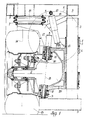
- bracket 1 is the member that supports the very suspension itself.
- the suspension is provided at the center position with a hub carier member 2 which forms the central member of said suspension and allows the rotation about the vertical axis in the way disclosed in the following.
- the bouncing/hoisting movements of the suspension occur along a wertical axle 3, which is preferably chromium plated and ground, through two bushes 4 realized with an antifriction material which are connected to the structure 5 of the vehicle.
- the grinding of the axle 3 is required in order to make use of said bushes 4.
- Said axle 3 is rigidly connected to the supporting bracket 1 by means of the anchoring members 6.
- Said bracket 1 in turn is anchored to the wheelhouse 8 of said structure 5 through the interposition of the spring 7 (to which reference will be made in the following).
- the ball joints 9 and 10 as well as the roll bearings 11 and 12 are provided on said bracket 1 which allow the rotation about the vertical axis to occur.
- the axis along which the ball joints 9 and 10 and the roll bearings 11 and 12 are arranged, which is pointed out with 13 in the Figure, is at 5° slope to the vertical.
- the ball joints 9 and 10 allow the radial loads to be absorbed whereas the roll bearings 11 and 12 will absorb the vertical loads.
- the choice of the roll bearings is mainly dictated by the need for limiting the vertical overall dimensions as far as possible.
- the roll bearings 11 and 12 as well as the bushes 4 are protected by gaskets which prevent dirt from leaking into the device.
- the slope of the axis 13 to the vertical is determined so as to reduce the lever arm between said axis 13 and the reaction axis 14 of the wheel to the minimum value allowed by the problems connected to the realization of the suspension itself.
- the elastic member of the suspension is made up of the air spring 7 acting cooperatively with the shock absorber damping member 15.
- a single member 11 is provided whose seat or housing can be obtained possibly direct inside the bracket 1.
- the damping member 15 is fastened at point indicated with reference 15' to the wheelhouse 8 of the structure 15, and at point indicated with reference 15" to the bracket 1 of the suspension.
- the air spring 7 acts both as the elastic member and as the hoisting member.
- the bouncing/hoisting movement can be also of the hydraulic type, realized through a jack placed between the spring 7 and the wheelhouse 8, so that the hoisting movement occurs through said jack, while the spring 7 acts just as the elastic member.
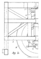
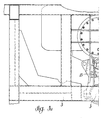
- the bracket 1 of the suspension is rigidly connected to the wheelhouse 8 of the structure 5 by means of a tie rod/strut 16 (see in particular Figures 2b and 3b).
- Said tie rod/strut 16 is provided in order to prevent the suspension from rotating freely about the vertical axle 3. Moreover, it supports loads acting in a direction parallel to the longitudinal axis of the vehicle, i.e. loads stemming from acceleration or braking as well as loads stemming from friction.
- tie rod/strut 16 is connected at point indicated with reference 16' to the structure 5 of the vehicle and at point indicated with reference 16" in the front part to the vertical axle 3 at a point corresponding to the upper anchoring member 6 through joints which do not prevent the wheel from undergoing bouncing/hoisting movements but, as already mentioned above, prevent the suspension itself from rotating freely about the vertical axle 3.
- the suspension illustrated in Figures 1 - 4 is also provided in addition with service disk brake with a mechanical spring and a mechanical caliper which is provided with a pneumatic unbraking spring and mechanical release for parking (pointed out with reference number 17).
- bracket 1 of the suspension according to the present invention which is realized as a single casting has been studied in a particular way so as to obtain a lever arm between the reaction axis 14 of the wheel on the ground and the axis of the structure (the axis with the reference number 18) of the lowest possible value to reduce to a minimum all stresses on the structure itself.
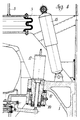
- the suspension according to the present invention is realized in such a way that it can be mounted both on motored and on unmotored wheels.
- Figure 5 shows an example of employment of said suspension in connection with a motored wheel.
- the reduction gear carrier 22 will be provided instead of the hub carrier 2.
- the motorization group 21 can be indifferently of the hydraulic or of the electric type.
Landscapes
- Engineering & Computer Science (AREA)
- Mechanical Engineering (AREA)
- Vehicle Body Suspensions (AREA)
- Arrangement Or Mounting Of Propulsion Units For Vehicles (AREA)
- Steering-Linkage Mechanisms And Four-Wheel Steering (AREA)
- Axle Suspensions And Sidecars For Cycles (AREA)
- Motorcycle And Bicycle Frame (AREA)
Priority Applications (1)
| Application Number | Priority Date | Filing Date | Title |
|---|---|---|---|
| AT87830156T ATE45124T1 (de) | 1986-04-29 | 1987-04-23 | Aufhaengung fuer angetriebene und nicht angetriebene raeder von fahrzeugen. |
Applications Claiming Priority (2)
| Application Number | Priority Date | Filing Date | Title |
|---|---|---|---|
| IT4795886 | 1986-04-29 | ||
| IT47958/86A IT1190546B (it) | 1986-04-29 | 1986-04-29 | Sospensione per ruote di veicoli motorizzate e non |
Publications (2)
| Publication Number | Publication Date |
|---|---|
| EP0245220A1 EP0245220A1 (en) | 1987-11-11 |
| EP0245220B1 true EP0245220B1 (en) | 1989-08-02 |
Family
ID=11263606
Family Applications (1)
| Application Number | Title | Priority Date | Filing Date |
|---|---|---|---|
| EP87830156A Expired EP0245220B1 (en) | 1986-04-29 | 1987-04-23 | A suspension for motored and unmotored wheels of vehicles |
Country Status (17)
| Country | Link |
|---|---|
| US (1) | US4783095A (es) |
| EP (1) | EP0245220B1 (es) |
| JP (1) | JPS6322709A (es) |
| KR (1) | KR870009871A (es) |
| CN (1) | CN1007800B (es) |
| AT (1) | ATE45124T1 (es) |
| AU (1) | AU7223387A (es) |
| BR (1) | BR8702072A (es) |
| CA (1) | CA1283930C (es) |
| DD (1) | DD273807A5 (es) |
| DE (1) | DE3760382D1 (es) |
| ES (1) | ES2010218B3 (es) |
| HU (1) | HUT49077A (es) |
| IL (1) | IL82284A0 (es) |
| IT (1) | IT1190546B (es) |
| SU (1) | SU1618279A3 (es) |
| ZA (1) | ZA872968B (es) |
Families Citing this family (22)
| Publication number | Priority date | Publication date | Assignee | Title |
|---|---|---|---|---|
| DE3734212A1 (de) * | 1986-12-10 | 1989-04-20 | Sterki Ag | Achse |
| AT391110B (de) * | 1988-10-17 | 1990-08-27 | Graef & Stift | Radfuehrung fuer lenkbare und antriebsfaehige raeder von kraftfahrzeugen |
| FR2669860B1 (fr) * | 1990-12-03 | 1993-06-18 | Peugeot | Dispositif formant suspension notamment pour une roue directrice d'un vehicule automobile. |
| US5597172A (en) * | 1995-10-17 | 1997-01-28 | Deere & Company | Sprayer suspension and steering |
| NL1002596C2 (nl) * | 1996-03-13 | 1997-09-17 | Transport Industry Dev Centre | Voertuig alsmede wielophanging voor een dergelijk voertuig. |
| US5865452C1 (en) * | 1997-03-05 | 2001-02-27 | Watson & Chalin Mfg Inc | Steerable suspension system |
| US6182984B1 (en) | 1999-04-06 | 2001-02-06 | Watson & Chalin Manufacturing, Inc. | Reversible caster steerable suspension system |
| US6390459B2 (en) | 1999-12-24 | 2002-05-21 | Yamashita Rubber Kabushiki Kaisha | Fluid-sealed anti-vibration device |
| US6416136B1 (en) | 2000-02-23 | 2002-07-09 | Fred P. Smith | Lightweight, adjustable-height, axle |
| BE1013399A3 (nl) * | 2000-04-20 | 2001-12-04 | Hool Nv Van | Verbeterde voorwielophanging voor bussen en dergelijke. |
| US6371237B1 (en) | 2000-09-06 | 2002-04-16 | Hagie Manufacturing Company | Steering system for variable height agricultural sprayer |
| US20040066015A1 (en) * | 2002-07-08 | 2004-04-08 | Kip Kilburn | Vehicle suspension system |
| WO2005042293A1 (en) * | 2003-10-03 | 2005-05-12 | Leblanc James C Sr | Wheel unit for automotive vehicles |
| US7766353B2 (en) * | 2003-10-03 | 2010-08-03 | Gpv, Llc | Wheel unit for automotive vehicles |
| EP1526011B1 (en) * | 2003-10-24 | 2008-07-09 | Nissan Motor Company, Limited | Independent suspension system for a wheeled vehicle |
| US20050280236A1 (en) * | 2004-06-16 | 2005-12-22 | Tony Vallejos | Independent front steering system for vehicles |
| CN101574722B (zh) * | 2009-03-16 | 2011-04-20 | 亚新科噪声与振动技术(安徽)有限公司 | 三角支架旋铆方法 |
| DE102011104154A1 (de) | 2011-06-14 | 2012-12-20 | Erhard Wullhorst | Einzelradaufhängung mit linear geführtem Querlenker |
| EA029747B1 (ru) * | 2014-05-15 | 2018-05-31 | Открытое Акционерное Общество "Минский Завод Колёсных Тягачей" | Независимая подвеска ведущего моста транспортного средства повышенной проходимости |
| US9475357B1 (en) * | 2015-04-13 | 2016-10-25 | Reyco Granning, Llc | Strut and air spring IFS assembly maximizing available steering knuckle wheel cut |
| CA3133724C (en) * | 2019-04-17 | 2022-07-05 | Ahishay SARDES | Suspension system and steering capabilities |
| US11602966B2 (en) * | 2020-07-02 | 2023-03-14 | Cnh Industrial America Llc | Independent linear suspension system |
Family Cites Families (7)
| Publication number | Priority date | Publication date | Assignee | Title |
|---|---|---|---|---|
| US2155521A (en) * | 1936-04-23 | 1939-04-25 | Cornelius D Scully | Front wheel suspension for motor vehicles |
| CH354343A (de) * | 1957-03-19 | 1961-05-15 | Inventio Ag | Abfederung an Fahrzeugen |
| FR1559244A (es) * | 1967-07-03 | 1969-03-07 | ||
| US3501039A (en) * | 1968-02-13 | 1970-03-17 | Robert U Mitsuyasu | Container handling and transporting vehicle |
| DE2554739A1 (de) * | 1975-12-05 | 1977-06-08 | Paus Gmbh Maschf Hermann | Radaufhaengung fuer fahrzeuge, insbesondere fuer den untertagebergbau |
| DE2848585A1 (de) * | 1978-11-09 | 1980-05-14 | Goldhofer Fahrzeugwerk | Achsaufhaengung fuer lenkbare achsen |
| DE3303551A1 (de) * | 1983-02-03 | 1984-08-09 | Volkswagenwerk Ag, 3180 Wolfsburg | Radfuehrendes federbein fuer die gelenkten raeder eines kraftfahrzeuges |
-
1986
- 1986-04-29 IT IT47958/86A patent/IT1190546B/it active
-
1987
- 1987-04-20 US US07/040,312 patent/US4783095A/en not_active Expired - Fee Related
- 1987-04-22 IL IL82284A patent/IL82284A0/xx unknown
- 1987-04-23 DE DE8787830156T patent/DE3760382D1/de not_active Expired
- 1987-04-23 ES ES87830156T patent/ES2010218B3/es not_active Expired
- 1987-04-23 AT AT87830156T patent/ATE45124T1/de not_active IP Right Cessation
- 1987-04-23 EP EP87830156A patent/EP0245220B1/en not_active Expired
- 1987-04-27 ZA ZA872968A patent/ZA872968B/xx unknown
- 1987-04-28 CN CN87103219A patent/CN1007800B/zh not_active Expired
- 1987-04-28 JP JP62106131A patent/JPS6322709A/ja active Pending
- 1987-04-28 DD DD87302220A patent/DD273807A5/de unknown
- 1987-04-28 SU SU874202479A patent/SU1618279A3/ru active
- 1987-04-28 BR BR8702072A patent/BR8702072A/pt not_active IP Right Cessation
- 1987-04-28 KR KR870004085A patent/KR870009871A/ko not_active Withdrawn
- 1987-04-29 HU HU871941A patent/HUT49077A/hu unknown
- 1987-04-29 AU AU72233/87A patent/AU7223387A/en not_active Abandoned
- 1987-04-29 CA CA000535951A patent/CA1283930C/en not_active Expired - Lifetime
Also Published As
| Publication number | Publication date |
|---|---|
| JPS6322709A (ja) | 1988-01-30 |
| ZA872968B (en) | 1987-10-20 |
| HUT49077A (en) | 1989-08-28 |
| IL82284A0 (en) | 1987-10-30 |
| KR870009871A (ko) | 1987-11-30 |
| EP0245220A1 (en) | 1987-11-11 |
| ATE45124T1 (de) | 1989-08-15 |
| CN1007800B (zh) | 1990-05-02 |
| US4783095A (en) | 1988-11-08 |
| IT1190546B (it) | 1988-02-16 |
| BR8702072A (pt) | 1988-02-09 |
| CN87103219A (zh) | 1987-11-11 |
| DE3760382D1 (en) | 1989-09-07 |
| CA1283930C (en) | 1991-05-07 |
| ES2010218B3 (es) | 1989-11-01 |
| SU1618279A3 (ru) | 1990-12-30 |
| DD273807A5 (de) | 1989-11-29 |
| IT8647958A0 (it) | 1986-04-29 |
| AU7223387A (en) | 1987-11-05 |
Similar Documents
| Publication | Publication Date | Title |
|---|---|---|
| EP0245220B1 (en) | A suspension for motored and unmotored wheels of vehicles | |
| US6113119A (en) | Assembly comprising a wheel and a suspension integrated into the wheel | |
| JP2921894B2 (ja) | 車両用の車輪とそのような車輪を装備した車両 | |
| US6257604B1 (en) | Assembly containing a wheel and a suspension integrated with the wheel | |
| US4996928A (en) | Integrated chassis and suspension systems for monorail vehicles | |
| US5188195A (en) | Vehicle driving wheel suspension system | |
| EP0254974A1 (en) | Rhomboidal geometry of an automotive vehicle | |
| KR950013753A (ko) | 차륜 현가장치 | |
| EP0931684B1 (en) | Electrically driven vehicle | |
| CA2090881A1 (en) | Suspension and shock absorber system for vehicles and trailers | |
| US4372418A (en) | Front set of wheels for an automobile vehicle | |
| JPH0620802B2 (ja) | 後輪の支持及び駆動装置 | |
| US4763920A (en) | Suspension for a wheel | |
| CN110667703A (zh) | 一种用于商用车的独立悬架车桥系统 | |
| CA1235607A (en) | Steerable truck for railway vehicle | |
| US3771813A (en) | Wheel suspension for individually suspended vehicle wheels | |
| EP0252549B1 (en) | Suspension of a steerable wheel | |
| SE447821B (sv) | Anordning for beredning av en charge av komposterbart material for en komposteringsanleggning | |
| US5082306A (en) | Vehicle suspension system providing continuous vertical orientation of the ground wheel | |
| US3042133A (en) | Independent wheel suspension | |
| US3877716A (en) | Wheel suspension for the steered wheels of vehicles including a disc brake | |
| JPH04505739A (ja) | 低床車両用の台車 | |
| JPS5836572Y2 (ja) | 車輌用タンデム型懸架装置 | |
| SU1154140A1 (ru) | Прицеп | |
| WO1991013786A1 (en) | Suspension system |
Legal Events
| Date | Code | Title | Description |
|---|---|---|---|
| PUAI | Public reference made under article 153(3) epc to a published international application that has entered the european phase |
Free format text: ORIGINAL CODE: 0009012 |
|
| AK | Designated contracting states |
Kind code of ref document: A1 Designated state(s): AT BE CH DE ES FR GB GR LI LU NL SE |
|
| 17P | Request for examination filed |
Effective date: 19880419 |
|
| 17Q | First examination report despatched |
Effective date: 19880803 |
|
| GRAA | (expected) grant |
Free format text: ORIGINAL CODE: 0009210 |
|
| AK | Designated contracting states |
Kind code of ref document: B1 Designated state(s): AT BE CH DE ES FR GB GR LI LU NL SE |
|
| PG25 | Lapsed in a contracting state [announced via postgrant information from national office to epo] |
Ref country code: SE Effective date: 19890802 Ref country code: NL Effective date: 19890802 Ref country code: LI Effective date: 19890802 Ref country code: GR Free format text: LAPSE BECAUSE OF FAILURE TO SUBMIT A TRANSLATION OF THE DESCRIPTION OR TO PAY THE FEE WITHIN THE PRESCRIBED TIME-LIMIT Effective date: 19890802 Ref country code: FR Free format text: THE PATENT HAS BEEN ANNULLED BY A DECISION OF A NATIONAL AUTHORITY Effective date: 19890802 Ref country code: CH Effective date: 19890802 Ref country code: AT Effective date: 19890802 |
|
| REF | Corresponds to: |
Ref document number: 45124 Country of ref document: AT Date of ref document: 19890815 Kind code of ref document: T |
|
| REF | Corresponds to: |
Ref document number: 3760382 Country of ref document: DE Date of ref document: 19890907 |
|
| REG | Reference to a national code |
Ref country code: CH Ref legal event code: PL |
|
| EN | Fr: translation not filed | ||
| NLV1 | Nl: lapsed or annulled due to failure to fulfill the requirements of art. 29p and 29m of the patents act | ||
| PG25 | Lapsed in a contracting state [announced via postgrant information from national office to epo] |
Ref country code: LU Free format text: LAPSE BECAUSE OF NON-PAYMENT OF DUE FEES Effective date: 19900430 |
|
| PLBE | No opposition filed within time limit |
Free format text: ORIGINAL CODE: 0009261 |
|
| STAA | Information on the status of an ep patent application or granted ep patent |
Free format text: STATUS: NO OPPOSITION FILED WITHIN TIME LIMIT |
|
| 26N | No opposition filed | ||
| PG25 | Lapsed in a contracting state [announced via postgrant information from national office to epo] |
Ref country code: GB Effective date: 19910423 |
|
| GBPC | Gb: european patent ceased through non-payment of renewal fee | ||
| PGFP | Annual fee paid to national office [announced via postgrant information from national office to epo] |
Ref country code: ES Payment date: 19920429 Year of fee payment: 6 |
|
| PGFP | Annual fee paid to national office [announced via postgrant information from national office to epo] |
Ref country code: BE Payment date: 19920513 Year of fee payment: 6 |
|
| PGFP | Annual fee paid to national office [announced via postgrant information from national office to epo] |
Ref country code: DE Payment date: 19920629 Year of fee payment: 6 |
|
| PG25 | Lapsed in a contracting state [announced via postgrant information from national office to epo] |
Ref country code: ES Free format text: LAPSE BECAUSE OF NON-PAYMENT OF DUE FEES Effective date: 19930424 |
|
| PG25 | Lapsed in a contracting state [announced via postgrant information from national office to epo] |
Ref country code: BE Effective date: 19930430 |
|
| BERE | Be: lapsed |
Owner name: JANUS BUS S.P.A. Effective date: 19930430 |
|
| PG25 | Lapsed in a contracting state [announced via postgrant information from national office to epo] |
Ref country code: DE Effective date: 19940101 |
|
| REG | Reference to a national code |
Ref country code: ES Ref legal event code: FD2A Effective date: 19990201 |