EP0244744A2 - Centrifugal sifter - Google Patents
Centrifugal sifter Download PDFInfo
- Publication number
- EP0244744A2 EP0244744A2 EP87106200A EP87106200A EP0244744A2 EP 0244744 A2 EP0244744 A2 EP 0244744A2 EP 87106200 A EP87106200 A EP 87106200A EP 87106200 A EP87106200 A EP 87106200A EP 0244744 A2 EP0244744 A2 EP 0244744A2
- Authority
- EP
- European Patent Office
- Prior art keywords
- rotors
- classifying
- housing
- rotor
- air
- Prior art date
- Legal status (The legal status is an assumption and is not a legal conclusion. Google has not performed a legal analysis and makes no representation as to the accuracy of the status listed.)
- Granted
Links
- 239000000463 material Substances 0.000 claims description 21
- 239000011362 coarse particle Substances 0.000 abstract 1
- 239000007787 solid Substances 0.000 abstract 1
- 239000000203 mixture Substances 0.000 description 5
- 239000002245 particle Substances 0.000 description 4
- 238000000926 separation method Methods 0.000 description 4
- 230000000007 visual effect Effects 0.000 description 3
- 230000000694 effects Effects 0.000 description 2
- 241000446313 Lamella Species 0.000 description 1
- 238000011010 flushing procedure Methods 0.000 description 1
- 230000000149 penetrating effect Effects 0.000 description 1
Images

Classifications
-
- B—PERFORMING OPERATIONS; TRANSPORTING
- B07—SEPARATING SOLIDS FROM SOLIDS; SORTING
- B07B—SEPARATING SOLIDS FROM SOLIDS BY SIEVING, SCREENING, SIFTING OR BY USING GAS CURRENTS; SEPARATING BY OTHER DRY METHODS APPLICABLE TO BULK MATERIAL, e.g. LOOSE ARTICLES FIT TO BE HANDLED LIKE BULK MATERIAL
- B07B7/00—Selective separation of solid materials carried by, or dispersed in, gas currents
- B07B7/08—Selective separation of solid materials carried by, or dispersed in, gas currents using centrifugal force
- B07B7/083—Selective separation of solid materials carried by, or dispersed in, gas currents using centrifugal force generated by rotating vanes, discs, drums, or brushes
Definitions
- the invention relates to a centrifugal classifier according to the preamble of patent claim 1.
- the invention has for its object to provide a classifier with even higher performance, from which several grain fractions with different separating grain sizes can be withdrawn at the same time, the individual fine grain fractions should have as little oversize and as little undersize as possible.
- the solution to this problem is specified in the characterizing part of claim 1. According to the invention, therefore, a plurality of classifying rotors are provided in a cuboid housing, from each of which a specific fine-grain fraction can be extracted.
- the rear view rotor in the flow direction preferably has a larger separating grain size than the front one.
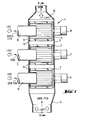
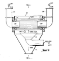
- three known rotors 2, 3, 4 are arranged one above the other in an elongated, box-shaped housing 1.
- the rotors are mounted on one housing wall 5 and driven by a separate drive 6, 7, 8.
- a tube penetrating the side wall 9 of the housing projects into the inside space of the rotor 2, 3, 4, so that each rotor is connected to a separate fine air outlet 10, 11, 12.
- the gap between a ring 13 connecting the rotor lamella at its free end and the wall 9 can be sealed by a labyrinth seal - with or without flushing medium.
- a conical or funnel-shaped classifying air classifying material inlet 14 is provided at the bottom.
- the view rotors 2, 3, 4 can have different separation limits. For this purpose, they can be driven at different speeds, operated with different suction, or they have different separation limits from the start (i.e. even with the same speed and suction).
- the lower (or in the flow direction first) classifying rotor 2 preferably has the smallest separating limit
- the middle classifying rotor 3 has a middle classifying limit
- the upper (or in the flow direction third) classifying rotor 4 has the largest classifying limit.
- the finest fine material is extracted from the lowermost / first outlet 10
- a medium fine material from the middle outlet 11 and a somewhat coarser fine material is extracted from the upper outlet 12 together with classifying air.
- a nozzle 15 is attached at the top, from which a remaining part of the classifying air together with still in this contained, relatively coarse material is extracted.
- the air flows are indicated by wide arrows, the particle flows by narrow arrows.
- the finest particle fraction is first extracted from the classifying material introduced below. This finest grain fraction is therefore no longer present above the lowest rotor 2. ⁇ The same applies to the middle and also to the upper view rotor 3,4. So you get several grain fractions with very "steep" grain distribution, i.e. with very little oversize and very little undersize.
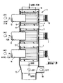
- FIGS. 3 and 4 corresponds essentially to that of FIGS. 1 and 2 (same parts are denoted by the same reference numerals), but with the difference that the particle mixture to be divided into several grain fractions by means of an inlet 16 arranged at the top / side in the Sifter housing 1 is entered, while a funnel-shaped coarse material outlet 17 is provided at the bottom, into which a classifying air inlet 18 opens laterally.
- This version is intended for coarser visual goods, at which the coarse material is too large or heavy to be discharged with a stream of air.
- the classifying rotors which are provided at a relatively short distance from one another, influence one another. In particular, adhering particles are separated (deagglomerated).
- the view rotors can rotate in the same direction or in opposite directions.
- the view rotors can also be operated at the same speed, i.e. of the same separation size, let it run if it is only the larger throughput that matters, i.e. large quantities of visible material are to be divided into only two grain fractions.
- 5 and 6 is particularly geared towards great performance.
- view rotors 19, 20 which are suctioned off on both sides and are several times longer and have a correspondingly higher performance.
- the classifying blades extend between rings 21 which are mounted on both sides in the housing 22.
- a piece of pipe 25 which is connected to a separate outlet channel 26 on the outside, which in this case extends upwards.
- One face ring 21 is driven, in FIG. 5 by V-belts.
- a funnel-shaped guiding device 23 Arranged underneath the rotors and symmetrically to them is a funnel-shaped guiding device 23 for a mixture of visible material and air, so that both classifying rotors 19, 20 are acted upon uniformly over their entire length.
- the coarse material is drawn off through a funnel-shaped lower housing attachment 24.
- suction rotors can be used if a correspondingly high output is important.
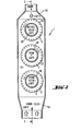
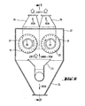
- each with four classifying rotors 30a, b, c are provided one above the other.
- the rotors 30a of the bottom row have the smallest
- the rotors 30b of the middle row have a middle
- the rotors 30c of the top row have a coarser separation size. Seen from the side, this arrangement corresponds to that according to FIG. 1. As in FIG. 1, several fine material fractions are obtained, but each in four times the amount.
- the visible-air mixture is introduced into the housing 22 at the bottom by means of pipes. Coarse material is discharged through a funnel-shaped lower housing part 24.
- separating rotors with a larger diameter can be arranged between those with a smaller diameter.
Landscapes
- Combined Means For Separation Of Solids (AREA)
- Cyclones (AREA)
Abstract
Description
Die Erfindung betrifft einen Zentrifugalkraftsichter gemäss dem Oberbegriff des Patentanspruchs 1.The invention relates to a centrifugal classifier according to the preamble of patent claim 1.
Bei den herkömmlichen Sichtern ist in dem Gehäuse nur ein an seinem Umfang mit den Sichtschaufeln bestücktes Sichtrad vorgesehen (z.B. DE-OS 16 07 631). Die Durchsatzleistung dieser Sichter ist begrenzt. Zur Leistungssteigerung wurde in einem Sichtergehäuse bereits ein Sichtrotor mit mehrfach längeren Sichtschaufeln angeordnet, der an beiden Stirnenden je einen Aus= lass für Feingut-Sichtluft-Gemisch aufweist, womit praktisch zwei oder mehr Sichter zusammengeschaltet sind. Die Sichtschaufeln können sich hierbei zwischen zwei in den Stirnwänden des Gehäuses gelagerten Stirnringen erstrecken (DB-PS 28 25 400) oder mittels Stützscheiben auf einer durchgehenden Welle montiert sein (DB-PS 29 51 819). Hiermit erreicht man zwar eine mehrfach grössere Durchsatzleistung bei grösserer Trennschärfe. Jedoch liefert bisher ein bestimmter Sichter bei einer bestimmten Drehzahl und einem bestimmten Luftdurchsatz immer nur eine bestimmte Trennkorngrösse.In the conventional classifiers, only one classifying wheel equipped with the classifying vanes is provided in the housing (eg DE-OS 16 07 631). The throughput of these classifiers is limited. In order to increase the performance, a classifying rotor with several longer blades has already been arranged in a classifier housing, which has an outlet for fine material / classifying air mixture on both ends, which practically connects two or more classifiers. The visible blades can extend between two end rings mounted in the end walls of the housing (DB-PS 28 25 400) or by means of Support disks must be mounted on a continuous shaft (DB-PS 29 51 819). With this one achieves a throughput that is several times greater with greater selectivity. However, up to now a certain classifier has only ever delivered a certain separating grain size at a certain speed and a certain air throughput.
Demgegenüber liegt der Erfindung die Aufgabe zugrunde, einen Sichter mit noch höherer Leistung zu schaffen, aus welchem gleichzeitig mehrere Kornfraktionen mit unterschiedlichen Trennkorngrössen abgezogen werden können, wobei die einzelnen Feinkornfraktionen möglichst wenig Überkorn und möglichst wenig Unterkorn aufweisen sollen. Die Lösung dieser Aufgabe ist in dem Kennzeichnungsteil des Patentanspruchs 1 angegeben. Gemäss der Erfindung sind also in einem quaderförmigen Gehäuse mehrere Sichtrotoren vorgesehen, aus denen jeweils eine bestimmte Feinkornfraktion abgesaugt werden kann.In contrast, the invention has for its object to provide a classifier with even higher performance, from which several grain fractions with different separating grain sizes can be withdrawn at the same time, the individual fine grain fractions should have as little oversize and as little undersize as possible. The solution to this problem is specified in the characterizing part of claim 1. According to the invention, therefore, a plurality of classifying rotors are provided in a cuboid housing, from each of which a specific fine-grain fraction can be extracted.
Vorzugsweise hat der in Strömungsrichtung jeweils hintere Sichtrotor eine grössere Trennkorngrösse als der vordere.The rear view rotor in the flow direction preferably has a larger separating grain size than the front one.
Weitere Ausgestaltungen sind in den Unteransprüchen angegeben.Further configurations are specified in the subclaims.
Zur näheren Erläuterung der Erfindung werden nachfolgend Ausführungsbeispiele anhand der Zeichnung beschrieben.In order to explain the invention in more detail, from examples of management described with reference to the drawing.
Es zeigen:
- Fig. 1 und 2 ein erstes Ausführungsbeispiel in zwei zueinander rechtwinkligen vertikalen Schnitten;
- Fig. 3 und 4 ein zweites Ausführungsbeispiel;
- Fig. 5 und 6 ein drittes Ausführungsbeispiel.
- Fig. 7 zeigt in einem vertikalen Querschnitt ein viertes Ausführungsbeispiel;
- Fig. 8 zeigt ein fünftes Ausführungsbeipsiel.
- 1 and 2 a first embodiment in two mutually perpendicular vertical sections;
- 3 and 4 a second embodiment;
- 5 and 6 a third embodiment.
- Fig. 7 shows a fourth embodiment in a vertical cross section;
- 8 shows a fifth exemplary embodiment.
Gemäss Fig. 1 und 2 sind in einem langgestreckten, kastenförmigen Gehäuse 1 drei an sich bekannte Sichtrotoren 2,3,4 übereinander angeordnet. Die Rotoren sind an der einen Gehäusewand 5 gelagert und durch je einen gesonderten Antrieb 6,7,8 angetrieben. An der anderen Seite ragt jeweils ein die Seitenwand 9 des Gehäuses durchsetzendes Rohr in den Innenraum des Rotors 2,3,4 hinein, womit also jeder Rotor an einen separaten Sichtluft-Feingut-Auslass 10,11,12 angeschlossen ist. Der Spalt zwischen einem die Rotorlamellen an ihrem freien Ende verbindenden Ring 13 und der Wand 9 kann durch eine Labyrinth-Dichtung - mit oder ohne Spülmedium - abgedichtet sein. Unten ist ein konischer bzw. trichterförmiger Sichtluft-Sichtgut-Einlass 14 vorgesehen.1 and 2, three known
Die Sichtrotoren 2,3,4 können unterschiedliche Trenngrenzen aufweisen. Zu diesem Zweck sind sie mit unterschiedlichen Drehzahlen antreibbar, mit unterschiedlichem Sog zu betreiben oder sie haben von Hause aus (also auch bei gleicher Drehzahl und gleichem Sog) unterschiedliche Trenngrenzen. Vorzugsweise hat der untere (bzw. in Strömungsrichtung erste) Sichtrotor 2 die kleinste Trenngrenze, der mittlere Sichtrotor 3 hat eine mittlere Trenngrenze und der obere (bzw. in Strömungsrichtung dritte) Sichtrotor 4 hat die grösste Trenngrenze.The
Somit wird aus dem untersten/ersten Auslass 10 das feinste Feingut, aus dem mittleren Auslass 11 ein mittleres Feingut und aus dem oberen Auslass 12 ein etwas gröberes Feingut jeweils zusammen mit Sichtluft abgesogen. Oben ist ein Stutzen 15 angesetzt, aus welchem ein restlicher Teil der Sichtluft zusammen mit noch in dieser enthaltenem, relativ grobem Gut abgesogen wird.Thus, the finest fine material is extracted from the lowermost /
Die Luftströme sind durch breite Pfeile, die Partikelströme durch schmale Pfeile angezeigt.The air flows are indicated by wide arrows, the particle flows by narrow arrows.
Mittels des untersten Sichtrotors 2 wird also aus dem unten eingeführten Sichtgut zunächst der feinste Partikelanteil abgezogen. Dieser feinste Kornanteil ist also oberhalb des untersten Rotors 2 nicht mehr vorhanden. `Entsprechendes gilt für den mittleren und auch für den oberen Sichtrotor 3,4. Man erhält dort also mehrere Kornfraktionen mit sehr "steiler" Kornverteilung, d.h. mit sehr wenig Uberkorn und sehr wenig Unterkorn.By means of the lowermost classifying rotor 2, the finest particle fraction is first extracted from the classifying material introduced below. This finest grain fraction is therefore no longer present above the lowest rotor 2. `The same applies to the middle and also to the
Die Ausführung nach Fig. 3 und 4 entspricht im wesentlichen derjenigen nach Fig. 1 und 2 (gleiche Teile sind mit gleichen Bezugszeichen bezeichnet), jedoch mit dem Unterschied, dass das in mehrere Kornfraktionen aufzuteilende Partikelgemisch mittels eines oben/seitlich angeordneten Einlasses 16 in das Sichtergehäuse 1 eingegeben wird, während unten ein trichterförmiger Grobgut-Auslass 17 vorgesehen ist, in welchen seitlich ein Sichtluft-Einlass 18 einmündet.3 and 4 corresponds essentially to that of FIGS. 1 and 2 (same parts are denoted by the same reference numerals), but with the difference that the particle mixture to be divided into several grain fractions by means of an
Diese Ausführung ist für gröberes Sichtgut vorgesehen, bei welchem das Grobgut zu gross bzw. schwer ist, um mit einem Sichtluftstrom ausgetragen zu werden.This version is intended for coarser visual goods, at which the coarse material is too large or heavy to be discharged with a stream of air.
Abgesehen von dem Effekt, dass das Sichtgut in mehr als zwei Kornfraktionen aufgeteilt wird, ergibt sich ein besserer Sichterwirkungsgrad.. Die mit relativ geringem Abstand voneinander vorgesehenen Sichtrotoren beeinflussen sich nämlich gegenseitig. Insbesondere werden zusammenhaftende Partikel getrennt (desagglomeriert).Apart from the effect that the material to be classified is divided into more than two grain fractions, there is a better classifying efficiency. The classifying rotors, which are provided at a relatively short distance from one another, influence one another. In particular, adhering particles are separated (deagglomerated).
Die Sichtrotoren können gleichsinnig oder gegensinnig umlaufen.The view rotors can rotate in the same direction or in opposite directions.
Ferner wird auch die Durchsatzleistung gesteigert.Throughput is also increased.
Gegebenenfalls kann man die Sichtrotoren auch mit gleicher Drehzahl, d.h. gleicher Trenngrösse, laufen lassen, wenn es nur auf die grössere Durchsatzleistung ankommt, also grosse Sichtgutmengen in nur zwei Kornfraktionen aufgeteilt werden sollen.If necessary, the view rotors can also be operated at the same speed, i.e. of the same separation size, let it run if it is only the larger throughput that matters, i.e. large quantities of visible material are to be divided into only two grain fractions.
Die Ausführung nach Fig. 5 und 6 ist besonders auf grosse Leistung abgestellt. Zu diesem Zweck sind beidseitig abgesaugte Sichtrotoren 19, 20 vorgesehen, die eine mehrfach grössere Länge und entsprechend grössere Leistung aufweisen. Die Sichterschaufeln erstrecken sich zwischen Ringen 21, die beidseits in dem Gehäuse 22 gelagert sind. In jeden Ring 21 ragt ein Rohrstück 25, welches aussen an je einen separaten Auslasskanal 26 angeschlossen ist, der sich in diesem Falle nach oben erstreckt. Jeweils ein Stirnring 21 ist angetrieben, in Fig.5 durch Keilriemen.5 and 6 is particularly geared towards great performance. For this purpose, view
Es können auch mehr als zwei beidseitig abgesaugte Sichtrotoren 19,20 vorgesehen sein, praktikabel sind z.B. drei Rotoren horizontal nebeneinander oder im Dreieck oder aber auch vier Rotoren im Viereck angeordnet.It is also possible to provide more than two classifying
Unterhalb der Rotoren und symmetrisch zu ihnen ist eine sich trichterförmig erweiternde Leitvorrichtung 23 für Sichtgut-Luft-Gemisch angeordnet, so dass beide Sichtrotoren 19, 20 gleichmässig über ihre ganze Länge beaufschlagt werden. Das Grobgut wird durch einen trichterförmigen unteren Gehäuseansatz 24 abgezogen.Arranged underneath the rotors and symmetrically to them is a funnel-shaped guiding
Es sei erwähnt, dass auch bei den Ausführungen nach Fig. 1 - 4 statt der einseitigen beidseitig abgesaugte Sichtrotoren eingesetzt werden können,wenn es auf entsprechend grosse Leistung ankommt.It should be mentioned that even in the embodiments according to FIGS. 1-4, instead of the one-sided suction rotors, suction rotors can be used if a correspondingly high output is important.
Bei der Ausführung nach Fig. 7 sind drei Reihen mit je vier Sichtrotoren 30a,b,c übereinander vorgesehen. Die Rotoren 30a der untersten Reihe haben die kleinste, die Rotoren 30b der mittleren Reihe eine mittlere und die Rotoren 30c der oberen Reihe eine gröbere Trenngrösse. Von der Seite gesehen entspricht diese Anordnung derjenigen nach Fig. 1. Wie bei Fig.l erhält man also mehrere Feingutfraktionen, jedoch jeweils in vierfach grösserer Menge. - In the embodiment according to FIG. 7, three rows, each with four classifying
Das Sichtgut-Luftgemisch wird unten mittels Rohren in das Gehäuse 22 eingeführt. Grobes Material wird durch einen trichterförmigen Gehäuseunterteil 24 abgeführt.The visible-air mixture is introduced into the
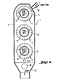
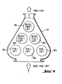
Bei der Ausführung nach Fig. 8 sind zuunterst drei Rotoren 30a nebeneinander und über/zwischen diesen zwei Rotoren 30b und über/ zwischen diesen schliesslich noch ein einzelner Rotor 30c vorgesehen. Aus den untersten Rotoren 30 a wird feines, aus den mittleren Rotoren 30b mittleres und aus dem obersten Rotor 30c gröberes Feingut abgezogen. Diese Anordnung trägt dem Umstand Rechnung, dass nach oben zu (bzw. in Strömungsrichtung) immer weniger Sichtgutgemisch vorhanden ist, also nach oben zu eine geringere Sichterdurchsatzleistung ausreicht. Die gegenseitige Beeinflussung der Rotoren ist bei dieser Ausführung besonders gross.In the embodiment according to FIG. 8, at the bottom three
Zur weiteren Steigerung dieses Effektes und noch besseren Raumausnutzung können jeweils zwischen Sichtrotoren mit grösserem Durchmesser solche mit kleinerem Durchmesser angeordnet sein.To further increase this effect and make even better use of space, separating rotors with a larger diameter can be arranged between those with a smaller diameter.
- 1 Gehäuse1 housing
- 2,3,4 Sichtrotoren2,3,4 classifying rotors
- 5 Gehäusewand5 housing wall
- 6,7,8 Antriebe6,7,8 drives
- 9 (andere) Seitenwand9 (other) side wall
- 10,11,12 Rohre (Auslässe)10,11,12 pipes (outlets)
- 13 Ringe13 rings
- 14 Sichtluft-Sichtgut-Einlass14 Visual air visual goods inlet
- 15 Stutzen15 sockets
- 16 Sichtgut-Einlass (Fig.3,4)16 visible material inlet (Fig. 3,4)
- 17 Grobgut-Auslass17 coarse material outlet
- 18 Sichtluft-Einlass18 Clear air inlet
- 19,20 Sichtrotoren, beidseitig, Fig. 5,619.20 view rotors, on both sides, Fig. 5,6
- 21 Ringe21 rings
- 22 Gehäuse22 housing
- 23 Leitvorrichtung23 guidance device
- 24 unterer Gehäuseansatz24 lower housing attachment
- 25 Rohrstücke25 pieces of pipe
- 26 getrennte Feingut-Sichluft-Auslasskanäle26 separate fine material clean air outlet channels
- 30a,b,c Sichtrotoren in Fig.7,830a, b, c view rotors in Fig. 7,8
Claims (4)
dadurch gekennzeichnet,
dass in einem im wesentlichen quaderförmigen Gehäuse (1; 22) mehrere Sichtrotoren (2,3,4;19,20) angeordnet sind, die an je einen separaten Sichtluft-Feingut-Auslass (10,11,12) je bzw. an zwei separate Sichtluft-Feingut-Auslässe (25,26) angeschlossen sind.1. centrifugal classifier with a housing provided with inlets and outlets for classifying air, classifying material, fine material and coarse material,
characterized,
that in a substantially cuboid housing (1; 22) a plurality of classifying rotors (2, 3, 4, 19, 20) are arranged, each on a separate fine air outlet (10, 11, 12) or on two separate fine air outlets (25, 26) are connected.
dadurch gekennzeichnet,
dass die Sichtrotoren parallel zueinander angeordnet sind.2. classifier according to claim 1,
characterized,
that the view rotors are arranged parallel to each other.
dadurch gekennzeichnet,
dass zwei oder mehr Reihen von nebeneinander angeordneten Sichtrotoren übereinander vorgesehen sind (Fig. 7,8).3. classifier according to claim 2,
characterized,
that two or more rows of side-by-side view rotors are provided one above the other (Fig. 7,8).
dadurch gekennzeichnet,
dass die Sichtrotoren jeweils einer Reihe gegenüber den Sichtrotoren jeweils einer anderen Reihe seitlich versetzt angeordnet sind (Fig. 8).4. classifier according to claim 3,
characterized,
that the classifying rotors in one row are laterally offset from the classifying rotors in another row (FIG. 8).
Priority Applications (1)
| Application Number | Priority Date | Filing Date | Title |
|---|---|---|---|
| AT87106200T ATE68113T1 (en) | 1986-05-07 | 1987-04-29 | CENTRIFUGAL FORCE SEPARATOR. |
Applications Claiming Priority (2)
| Application Number | Priority Date | Filing Date | Title |
|---|---|---|---|
| DE19863615494 DE3615494A1 (en) | 1986-05-07 | 1986-05-07 | CENTRIFUGAL FORCE SIGHTER |
| DE3615494 | 1986-05-07 |
Publications (3)
| Publication Number | Publication Date |
|---|---|
| EP0244744A2 true EP0244744A2 (en) | 1987-11-11 |
| EP0244744A3 EP0244744A3 (en) | 1989-05-17 |
| EP0244744B1 EP0244744B1 (en) | 1991-10-09 |
Family
ID=6300365
Family Applications (1)
| Application Number | Title | Priority Date | Filing Date |
|---|---|---|---|
| EP87106200A Expired - Lifetime EP0244744B1 (en) | 1986-05-07 | 1987-04-29 | Centrifugal sifter |
Country Status (7)
| Country | Link |
|---|---|
| US (1) | US4857178A (en) |
| EP (1) | EP0244744B1 (en) |
| JP (1) | JPS6328477A (en) |
| AT (1) | ATE68113T1 (en) |
| DE (2) | DE3615494A1 (en) |
| ES (1) | ES2026861T3 (en) |
| GR (1) | GR3003247T3 (en) |
Cited By (2)
| Publication number | Priority date | Publication date | Assignee | Title |
|---|---|---|---|---|
| EP0818249A1 (en) * | 1996-07-08 | 1998-01-14 | PMT Gesteinsvermahlungstechnik | Classifying rotor for pneumatic separator |
| US6318561B1 (en) | 1998-11-27 | 2001-11-20 | Hosokawa Alpine Aktiengesellschaft & Co. Ohg | Air classifier |
Families Citing this family (7)
| Publication number | Priority date | Publication date | Assignee | Title |
|---|---|---|---|---|
| DE3814458A1 (en) * | 1988-04-28 | 1989-11-09 | Krupp Polysius Ag | Air separator |
| JP2936863B2 (en) * | 1992-01-14 | 1999-08-23 | ヤマハ株式会社 | Tone control device for musical tone signal forming device |
| US5259510A (en) * | 1992-03-31 | 1993-11-09 | Edward Lowe Industries, Inc. | Apparatus for separating and removing fine particulates from a particle flow |
| DE19943528A1 (en) * | 1999-09-11 | 2001-03-15 | Kloeckner Humboldt Wedag | Sifter for granular material has sifter basket with extending projecting necks, and V-belt drive engaging on one neck |
| KR100886197B1 (en) | 2008-05-29 | 2009-02-27 | 주식회사 우양이엠에스 | Dust collector |
| JP5151940B2 (en) * | 2008-12-03 | 2013-02-27 | 株式会社リコー | Classification device |
| DE102018132155B3 (en) | 2018-12-13 | 2019-12-12 | Netzsch-Feinmahltechnik Gmbh | FLOWERS WITH SPECIAL FAN WHEEL |
Citations (3)
| Publication number | Priority date | Publication date | Assignee | Title |
|---|---|---|---|---|
| DE2951819A1 (en) * | 1979-12-21 | 1981-09-03 | Omya GmbH, 5000 Köln | Turbo-centrifugal separator for solid particles - has outlet for air and fines at each end of rotor shaft |
| EP0115057A2 (en) * | 1983-01-29 | 1984-08-08 | Alpine Aktiengesellschaft | Pneumatic separator in the field of fine material |
| EP0226987A2 (en) * | 1985-12-21 | 1987-07-01 | O & K Orenstein & Koppel Aktiengesellschaft | Device for classifying powdery bulk material |
Family Cites Families (11)
| Publication number | Priority date | Publication date | Assignee | Title |
|---|---|---|---|---|
| US535099A (en) * | 1895-03-05 | meadon | ||
| DE870996C (en) * | 1944-04-19 | 1953-03-19 | Mannesmann Ag | Process for the production of valuable, especially low-boiling, hydrocarbon oils from hard coal by cracking |
| US2953307A (en) * | 1956-10-15 | 1960-09-20 | Microcylclomat Co | Synergistic fluid energy reducing and classifying unit |
| US2973094A (en) * | 1958-09-02 | 1961-02-28 | Claude B Schneible Co | Separating apparatus and method |
| DE1507729A1 (en) * | 1966-07-05 | 1970-01-08 | Polysius Ag | Air separator |
| DE1607631A1 (en) * | 1967-07-27 | 1970-10-22 | Krupp Gmbh | Air separator |
| DE2117552B2 (en) * | 1971-04-10 | 1973-08-16 | G Siempelkamp & Co, 4150 Krefeld | Centrifugal sifter - for powdered and granulated materials |
| JPS51147059A (en) * | 1975-06-13 | 1976-12-17 | Nobuo Yoshimori | Apparatus for classification |
| US4108778A (en) * | 1976-02-25 | 1978-08-22 | Lambert Steven J | Self-cleaning filter and vortexer |
| DE2825400C2 (en) * | 1978-06-09 | 1984-02-02 | Omya Gmbh, 5000 Koeln | Cutting machine |
| JPS5980375A (en) * | 1982-10-27 | 1984-05-09 | ラサ工業株式会社 | Multistage centrifugal sorter |
-
1986
- 1986-05-07 DE DE19863615494 patent/DE3615494A1/en active Granted
-
1987
- 1987-04-29 DE DE8787106200T patent/DE3773530D1/en not_active Expired - Fee Related
- 1987-04-29 ES ES198787106200T patent/ES2026861T3/en not_active Expired - Lifetime
- 1987-04-29 EP EP87106200A patent/EP0244744B1/en not_active Expired - Lifetime
- 1987-04-29 AT AT87106200T patent/ATE68113T1/en not_active IP Right Cessation
- 1987-05-01 US US07/044,830 patent/US4857178A/en not_active Expired - Lifetime
- 1987-05-07 JP JP62111635A patent/JPS6328477A/en active Granted
-
1991
- 1991-12-02 GR GR91401874T patent/GR3003247T3/en unknown
Patent Citations (3)
| Publication number | Priority date | Publication date | Assignee | Title |
|---|---|---|---|---|
| DE2951819A1 (en) * | 1979-12-21 | 1981-09-03 | Omya GmbH, 5000 Köln | Turbo-centrifugal separator for solid particles - has outlet for air and fines at each end of rotor shaft |
| EP0115057A2 (en) * | 1983-01-29 | 1984-08-08 | Alpine Aktiengesellschaft | Pneumatic separator in the field of fine material |
| EP0226987A2 (en) * | 1985-12-21 | 1987-07-01 | O & K Orenstein & Koppel Aktiengesellschaft | Device for classifying powdery bulk material |
Cited By (3)
| Publication number | Priority date | Publication date | Assignee | Title |
|---|---|---|---|---|
| EP0818249A1 (en) * | 1996-07-08 | 1998-01-14 | PMT Gesteinsvermahlungstechnik | Classifying rotor for pneumatic separator |
| US5957299A (en) * | 1996-07-08 | 1999-09-28 | Keuschnigg; Josef | Separator wheel for an air separator |
| US6318561B1 (en) | 1998-11-27 | 2001-11-20 | Hosokawa Alpine Aktiengesellschaft & Co. Ohg | Air classifier |
Also Published As
| Publication number | Publication date |
|---|---|
| EP0244744B1 (en) | 1991-10-09 |
| JPH0369590B2 (en) | 1991-11-01 |
| US4857178A (en) | 1989-08-15 |
| DE3615494C2 (en) | 1988-04-07 |
| ES2026861T3 (en) | 1992-05-16 |
| GR3003247T3 (en) | 1993-02-17 |
| JPS6328477A (en) | 1988-02-06 |
| DE3615494A1 (en) | 1987-11-12 |
| ATE68113T1 (en) | 1991-10-15 |
| EP0244744A3 (en) | 1989-05-17 |
| DE3773530D1 (en) | 1991-11-14 |
Similar Documents
| Publication | Publication Date | Title |
|---|---|---|
| DE2818791C2 (en) | Cyclone separator with axial flow | |
| DE1782775C3 (en) | ||
| EP0199003B1 (en) | Rotary air classifier with a centrifugal cage | |
| EP0244744B1 (en) | Centrifugal sifter | |
| DE69016342T2 (en) | Centrifuge for cleaning gas flows and the method used for this cleaner. | |
| DE1757582C2 (en) | Centrifugal basket wind sifter | |
| DE3426294A1 (en) | Cyclone recirculating-air screen for screening material with varying particle size, in particular cement | |
| DE1482454B1 (en) | Circulating air separator | |
| DE2036891A1 (en) | Powder separator - having two sets of rotating vanes | |
| DE3910349A1 (en) | PAPER MATERIAL PROCESSING DEVICE | |
| DE1160763B (en) | Device for opening and cleaning fiber material, in particular asbestos fibers | |
| DE3418635C2 (en) | ||
| DE2710543C2 (en) | ||
| DE69824609T2 (en) | DEVICE FOR CLEANING A SUSPENSION, ESPECIALLY A SUSPENSION FROM A FIBER MASS | |
| EP0491278A2 (en) | Method and device for dedusting and/or classifying granular or fibrous material in an air stream | |
| DE3615493C2 (en) | ||
| DE693753C (en) | Dust separator, especially for dedusting the coal before washing | |
| DE1507688C2 (en) | Process for the continuous sifting of granular material on a dry route | |
| DE965744C (en) | Sifter with tangential feeding of the well-loaded carrier | |
| CH656328A5 (en) | METHOD FOR SIGHTING BULK GOODS AND DEVICE FOR IMPLEMENTING THE METHOD. | |
| DE2220534A1 (en) | ROTARY FLOW EIRBLER FOR SEPARATION AND SEPARATION OF FINE-GRAIN PARTICLES | |
| DE974442C (en) | Device for breaking down the dust suspended in a medium into coarse and fine grains | |
| DE638170C (en) | Device for sifting with a blower sucking in the dust air mixture | |
| DE1482455C (en) | Air separator | |
| DE2649382A1 (en) | Centrifugal wind sifter with even sifting over entire length - has area of openings between suction pipe and chamber decreasing in flow direction |
Legal Events
| Date | Code | Title | Description |
|---|---|---|---|
| PUAI | Public reference made under article 153(3) epc to a published international application that has entered the european phase |
Free format text: ORIGINAL CODE: 0009012 |
|
| AK | Designated contracting states |
Kind code of ref document: A2 Designated state(s): AT BE CH DE ES FR GB GR IT LI NL SE |
|
| PUAL | Search report despatched |
Free format text: ORIGINAL CODE: 0009013 |
|
| AK | Designated contracting states |
Kind code of ref document: A3 Designated state(s): AT BE CH DE ES FR GB GR IT LI NL SE |
|
| 17P | Request for examination filed |
Effective date: 19890531 |
|
| 17Q | First examination report despatched |
Effective date: 19900320 |
|
| GRAA | (expected) grant |
Free format text: ORIGINAL CODE: 0009210 |
|
| AK | Designated contracting states |
Kind code of ref document: B1 Designated state(s): AT BE CH DE ES FR GB GR IT LI NL SE |
|
| REF | Corresponds to: |
Ref document number: 68113 Country of ref document: AT Date of ref document: 19911015 Kind code of ref document: T |
|
| REF | Corresponds to: |
Ref document number: 3773530 Country of ref document: DE Date of ref document: 19911114 |
|
| GBT | Gb: translation of ep patent filed (gb section 77(6)(a)/1977) | ||
| ITF | It: translation for a ep patent filed | ||
| ET | Fr: translation filed | ||
| REG | Reference to a national code |
Ref country code: ES Ref legal event code: FG2A Ref document number: 2026861 Country of ref document: ES Kind code of ref document: T3 |
|
| PLBI | Opposition filed |
Free format text: ORIGINAL CODE: 0009260 |
|
| 26 | Opposition filed |
Opponent name: ALPINE AKTIENGESELLSCHAFT Effective date: 19920703 |
|
| NLR1 | Nl: opposition has been filed with the epo |
Opponent name: ALPINE AKTIENGESELLSCHAFT |
|
| REG | Reference to a national code |
Ref country code: GR Ref legal event code: FG4A Free format text: 3003247 |
|
| PLBN | Opposition rejected |
Free format text: ORIGINAL CODE: 0009273 |
|
| STAA | Information on the status of an ep patent application or granted ep patent |
Free format text: STATUS: OPPOSITION REJECTED |
|
| 27O | Opposition rejected |
Effective date: 19930329 |
|
| NLR2 | Nl: decision of opposition | ||
| EAL | Se: european patent in force in sweden |
Ref document number: 87106200.6 |
|
| PGFP | Annual fee paid to national office [announced via postgrant information from national office to epo] |
Ref country code: GB Payment date: 20010327 Year of fee payment: 15 |
|
| PGFP | Annual fee paid to national office [announced via postgrant information from national office to epo] |
Ref country code: GR Payment date: 20010329 Year of fee payment: 15 |
|
| PGFP | Annual fee paid to national office [announced via postgrant information from national office to epo] |
Ref country code: SE Payment date: 20010411 Year of fee payment: 15 Ref country code: AT Payment date: 20010411 Year of fee payment: 15 |
|
| PGFP | Annual fee paid to national office [announced via postgrant information from national office to epo] |
Ref country code: FR Payment date: 20010420 Year of fee payment: 15 |
|
| PGFP | Annual fee paid to national office [announced via postgrant information from national office to epo] |
Ref country code: BE Payment date: 20010423 Year of fee payment: 15 |
|
| PGFP | Annual fee paid to national office [announced via postgrant information from national office to epo] |
Ref country code: NL Payment date: 20010424 Year of fee payment: 15 |
|
| PGFP | Annual fee paid to national office [announced via postgrant information from national office to epo] |
Ref country code: CH Payment date: 20010430 Year of fee payment: 15 |
|
| PGFP | Annual fee paid to national office [announced via postgrant information from national office to epo] |
Ref country code: DE Payment date: 20010510 Year of fee payment: 15 |
|
| PGFP | Annual fee paid to national office [announced via postgrant information from national office to epo] |
Ref country code: ES Payment date: 20010514 Year of fee payment: 15 |
|
| REG | Reference to a national code |
Ref country code: GB Ref legal event code: IF02 |
|
| PG25 | Lapsed in a contracting state [announced via postgrant information from national office to epo] |
Ref country code: GB Free format text: LAPSE BECAUSE OF NON-PAYMENT OF DUE FEES Effective date: 20020429 Ref country code: AT Free format text: LAPSE BECAUSE OF NON-PAYMENT OF DUE FEES Effective date: 20020429 |
|
| PG25 | Lapsed in a contracting state [announced via postgrant information from national office to epo] |
Ref country code: SE Free format text: LAPSE BECAUSE OF NON-PAYMENT OF DUE FEES Effective date: 20020430 Ref country code: LI Free format text: LAPSE BECAUSE OF NON-PAYMENT OF DUE FEES Effective date: 20020430 Ref country code: ES Free format text: LAPSE BECAUSE OF NON-PAYMENT OF DUE FEES Effective date: 20020430 Ref country code: CH Free format text: LAPSE BECAUSE OF NON-PAYMENT OF DUE FEES Effective date: 20020430 Ref country code: BE Free format text: LAPSE BECAUSE OF NON-PAYMENT OF DUE FEES Effective date: 20020430 |
|
| PG25 | Lapsed in a contracting state [announced via postgrant information from national office to epo] |
Ref country code: NL Free format text: LAPSE BECAUSE OF NON-PAYMENT OF DUE FEES Effective date: 20021101 Ref country code: DE Free format text: LAPSE BECAUSE OF NON-PAYMENT OF DUE FEES Effective date: 20021101 |
|
| PG25 | Lapsed in a contracting state [announced via postgrant information from national office to epo] |
Ref country code: GR Free format text: LAPSE BECAUSE OF NON-PAYMENT OF DUE FEES Effective date: 20021105 |
|
| EUG | Se: european patent has lapsed |
Ref document number: 87106200.6 |
|
| REG | Reference to a national code |
Ref country code: CH Ref legal event code: PL |
|
| GBPC | Gb: european patent ceased through non-payment of renewal fee |
Effective date: 20020429 |
|
| PG25 | Lapsed in a contracting state [announced via postgrant information from national office to epo] |
Ref country code: FR Free format text: LAPSE BECAUSE OF NON-PAYMENT OF DUE FEES Effective date: 20021231 |
|
| NLV4 | Nl: lapsed or anulled due to non-payment of the annual fee |
Effective date: 20021101 |
|
| REG | Reference to a national code |
Ref country code: FR Ref legal event code: ST |
|
| REG | Reference to a national code |
Ref country code: ES Ref legal event code: FD2A Effective date: 20030514 |
|
| PG25 | Lapsed in a contracting state [announced via postgrant information from national office to epo] |
Ref country code: IT Free format text: LAPSE BECAUSE OF NON-PAYMENT OF DUE FEES;WARNING: LAPSES OF ITALIAN PATENTS WITH EFFECTIVE DATE BEFORE 2007 MAY HAVE OCCURRED AT ANY TIME BEFORE 2007. THE CORRECT EFFECTIVE DATE MAY BE DIFFERENT FROM THE ONE RECORDED. Effective date: 20050429 |