EP0244731A2 - Locking arrangement for a unit load - Google Patents
Locking arrangement for a unit load Download PDFInfo
- Publication number
- EP0244731A2 EP0244731A2 EP87106099A EP87106099A EP0244731A2 EP 0244731 A2 EP0244731 A2 EP 0244731A2 EP 87106099 A EP87106099 A EP 87106099A EP 87106099 A EP87106099 A EP 87106099A EP 0244731 A2 EP0244731 A2 EP 0244731A2
- Authority
- EP
- European Patent Office
- Prior art keywords
- opening
- locking plate
- locking
- arrangement according
- frame element
- Prior art date
- Legal status (The legal status is an assumption and is not a legal conclusion. Google has not performed a legal analysis and makes no representation as to the accuracy of the status listed.)
- Granted
Links
Images

Classifications
-
- B—PERFORMING OPERATIONS; TRANSPORTING
- B65—CONVEYING; PACKING; STORING; HANDLING THIN OR FILAMENTARY MATERIAL
- B65B—MACHINES, APPARATUS OR DEVICES FOR, OR METHODS OF, PACKAGING ARTICLES OR MATERIALS; UNPACKING
- B65B13/00—Bundling articles
- B65B13/18—Details of, or auxiliary devices used in, bundling machines or bundling tools
- B65B13/24—Securing ends of binding material
- B65B13/34—Securing ends of binding material by applying separate securing members, e.g. deformable clips
-
- B—PERFORMING OPERATIONS; TRANSPORTING
- B60—VEHICLES IN GENERAL
- B60P—VEHICLES ADAPTED FOR LOAD TRANSPORTATION OR TO TRANSPORT, TO CARRY, OR TO COMPRISE SPECIAL LOADS OR OBJECTS
- B60P7/00—Securing or covering of load on vehicles
- B60P7/06—Securing of load
- B60P7/13—Securing freight containers or forwarding containers on vehicles
-
- Y—GENERAL TAGGING OF NEW TECHNOLOGICAL DEVELOPMENTS; GENERAL TAGGING OF CROSS-SECTIONAL TECHNOLOGIES SPANNING OVER SEVERAL SECTIONS OF THE IPC; TECHNICAL SUBJECTS COVERED BY FORMER USPC CROSS-REFERENCE ART COLLECTIONS [XRACs] AND DIGESTS
- Y10—TECHNICAL SUBJECTS COVERED BY FORMER USPC
- Y10T—TECHNICAL SUBJECTS COVERED BY FORMER US CLASSIFICATION
- Y10T24/00—Buckles, buttons, clasps, etc.
- Y10T24/28—Freight container to freight container fastener
Definitions
- the invention relates to an arrangement for locking a loading unit, i.e. a container or a transport platform, on a locking element by means of a locking plate, according to the first part of patent claim 1.
- the locking plate can be moved in the longitudinal direction of a lower container frame element and exits in the area of a corner fitting.
- the locking point is located near the front or rear edge of the container.
- the invention has for its object to provide an arrangement with which medium-sized loading units can be locked at only two points in such a way that there is no risk of tipping over even with vertical accelerations.
- the locking plate then engages in a forklift opening which is arranged on the side of the loading unit at a distance from the two corners for fixing to the locking element in question.
- the locking plate and the opening are matched to one another in such a way that a larger part of the locking plate abuts the outer or inner surface of the opening. Since the same locks are provided on both longitudinally running lower frame elements of the loading unit, it is locked in the transverse direction. Since fer ner for engaging the locking plate, the forklift openings that are regularly available in containers and platforms can be used to lock conventional loading units without special measures using the locking plate.
- a part of the loading unit is located in front of and behind the locking point, so that it is secured against tipping over both its front and its rear lower edge.
- the locking plate can be simple in shape and inexpensive to manufacture and at the same time easy to handle in operation.
- the container shown in FIG. 1 has a frame, the different frame elements of which are connected to one another at corner fittings.
- the lower frame elements 10 extending in the longitudinal direction of the loading area indicated in FIG. 1 are pierced between the corner fittings 9 by two forklift trucks, one of which is used to fix the container to locking elements, such as are provided on the loading area of vehicles for transporting ISO and large country containers, is used.
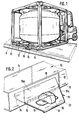
- FIG. 2 A part of the lower frame element 10 is shown in a perspective view in FIG. 2.
- the outer wall 11 facing away from the container is provided with a rectangular opening 12, the greater length of which extends in the longitudinal direction of the frame element.
- the frame element 10 consists of a square tube, with the opening 12 in the wall 11 aligning an opening 14 of the same size in the opposite inner vertical wall; the two openings 12 and 14 form a pocket for the insertion of forklift tines.
- the upper flange of the frame element 10 is provided with a reinforcing plate (not shown) in the region of the openings 12 and 14.
- a locking plate 15 is inserted, which is designed trapezoidal according to FIG. 2, wherein the rear edge 16 of the locking plate 15 is longer than the front edge 17 and longer than the lower edge 13 of the opening 12.
- Der aus Part 15a of the locking plate 15 protruding from the opening 12 has an elongated recess 18 into which a rotary lock 19 provided for securing large containers engages.
- the rotary lock 19 is shown in its locked position.
- the locking plate 15 is provided with a web 23 which is angled downwards and whose height is equal to the distance between the lower edge 13 of the opening 12 and the loading area of the vehicle.
- Locking plate 15 is rounded at 24 in its part 15b which engages in the opening 12. As a result, it can first be inserted into the opening 12 with its rear tip on the right in FIG. 2 and then screwed in in a diagonal alignment with the rounded part. Then the locking plate 15 is lowered until it rests on the lower edge 13 of the opening 12.
- the recess 18 is guided over the rotary lock 19, which is initially in a position rotated by 90 ° with respect to the illustration in FIG. 2.
- the rotary lock 19 By turning the rotary lock 19 in the position shown in FIG. 2, the locking plate 15 is then braced against the lower edge 13 of the opening 12 and with its web 23 against the loading surface, whereby the container is locked.
- the forklift bag is arranged in the longitudinally lower container frame element 10 between the two corner fittings 9, the described type of locking prevents the container from tipping over its front and rear edges.
- the container is also secured against tipping about each longitudinal axis.
- the part 25a of the locking plate 25 protruding from the opening 12 of the container frame element 10 is offset by lateral incisions 26 in relation to the part 25b engaging in the opening.
- both parts of the locking plate can be rectangular, the part 25a protruding from the opening and provided with the recess 18 being somewhat shorter than the lower edge 13 of the opening 12, while the other part 25b is longer than this edge 13 but somewhat shorter than the diagonal dimension of the opening 12.
- the locking plate 25 according to FIG. 3 is also on its inner part 25b rounded off at 24.
- the locking plate 35 shown in FIG. 4 differs from the locking plate 25 according to FIG. 3 in that the lateral incisions are designed as slots 36.
- FIG. 5 shows a container frame element 20 in the form of an I-beam, an opening 22 forming the forklift track being arranged in the central web 21.
- the opening 22 has a slot 27 on its upper edge which extends beyond its length.
- the locking plate 15, 25 or 35 can be guided horizontally with its wider rear part through the slot 27 and then lowered vertically downwards.
- the locking plate 45 has a wider outer part 45a, which is provided with the opening 18 for engaging the rotary lock 19, and a narrower, straight part 45b for engaging in the opening 12.
- the part 45b is somewhat narrower, the part 45a, on the other hand, wider than the opening 12.
- the container is secured against displacement in the direction of the rotary lock 19. Since forklift openings 12 are usually provided on both lower, longitudinally extending container frame elements 20 n corresponding points, the same locking, as shown in Fig. 6, can also be carried out on the opposite side of the container, so that then Container as in the embodiment of FIG. 2 is secured against shifting in both transverse directions and against tipping about each transverse axis.
Landscapes
- Engineering & Computer Science (AREA)
- Mechanical Engineering (AREA)
- Transportation (AREA)
- Forklifts And Lifting Vehicles (AREA)
- Basic Packing Technique (AREA)
- Supplying Of Containers To The Packaging Station (AREA)
- Measurement Of Force In General (AREA)
- Load-Engaging Elements For Cranes (AREA)
- Pallets (AREA)
- Lock And Its Accessories (AREA)
- Prostheses (AREA)
- Fittings On The Vehicle Exterior For Carrying Loads, And Devices For Holding Or Mounting Articles (AREA)
- Closures For Containers (AREA)
- Warehouses Or Storage Devices (AREA)
- Rigid Containers With Two Or More Constituent Elements (AREA)
Abstract
Zum Arretieren eines Containers dient eine Riegelplatte (15), die in eine in einem unteren Container-Rahmenelement (10) vorgesehene Gabelstapleröffnung (12) eingreift und in einem aus dieser herausragenden Teil (15a) eine Aussparung (18) zum Eingriff mit einem Drehschloß (19) aufweist. Die Öffnung (12) befindet sich an einer mittleren Stelle des Rahmenelements (10) zwischen den jeweiligen Ecken, so daß der Container gegen Kippen um seine vordere und seine hintere Kante gesichert ist. Öffnung (12) und Riegelplatte (15) sind in ihrer Formgebung so aufeinander abgestimmt, daß der Container auch in Querrichtung verriegelt ist.To lock a container, a locking plate (15) is used, which engages in a forklift opening (12) provided in a lower container frame element (10) and in a part (15a) protruding therefrom a recess (18) for engagement with a rotary lock ( 19). The opening (12) is located at a central point of the frame element (10) between the respective corners, so that the container is secured against tipping over its front and rear edges. The shape of the opening (12) and locking plate (15) are matched to one another in such a way that the container is also locked in the transverse direction.
Description
Die Erfindung betrifft eine Anordnung zum Arretieren einer Ladeeinheit, d.h. eines Containers oder einer Transportplattform, an einem Arretierungselement mittels einer Riegelplatte, gemäß dem ersten Teil des Patentanspruchs 1.The invention relates to an arrangement for locking a loading unit, i.e. a container or a transport platform, on a locking element by means of a locking plate, according to the first part of patent claim 1.
Eine derartige Anordnung gehört gemäß der nicht vorveröffentlichten EP-A2-0 189 054 zum Stand der Technik. Dort ist die Riegelplatte in Längsrichtung eines unteren Container-Rahmenelementes verschiebbar und tritt im Bereich eines Eckbeschlags nach außen. Im arretierten Zustand liegt dabei ebenso wie bei herkömmlichen Verriegelungen der Arretierungspunkt in der Nähe der vorderen bzw. hinteren Containerkante. Um bei Auftreten von Vertikalbeschleunigungen, die insbesondere bei Straßenfahrzeugen zu berücksichtigen sind, die Gefahr eines Kippens um die betreffende vordere oder hintere Containerkante zu vermeiden, sind über die Arretierung an zwei ISO-Drehschlössern hinaus zusätzliche Befestigungsmaßnahmen erforderlich.According to EP-A2-0 189 054, which has not been published beforehand, such an arrangement is part of the prior art. There, the locking plate can be moved in the longitudinal direction of a lower container frame element and exits in the area of a corner fitting. In the locked state, as with conventional locks, the locking point is located near the front or rear edge of the container. In order to avoid the risk of tipping over the relevant front or rear container edge in the event of vertical accelerations, which must be taken into account particularly in road vehicles, additional fastening measures are required in addition to the lock on two ISO rotary locks.
Der Erfindung liegt die Aufgabe zugrunde, eine Anordnung zu schaffen, mit der sich mittelgroße Ladeeinheiten jeweils an lediglich zwei Punkten derart arretieren läßt, daß auch bei Vertikalbeschleunigungen keine Kippgefahr auftritt.The invention has for its object to provide an arrangement with which medium-sized loading units can be locked at only two points in such a way that there is no risk of tipping over even with vertical accelerations.
Die erfindungsgemäße Lösung dieser Aufgabe ist im Patentanspruch 1 angegeben. Danach greift die Riegelplatte zur Fixierung an dem betreffenden Arretierungselement in eine Gabelstapleröffnung ein, die seitlich an der Ladeeinheit in Abstand von den beiden Ecken angeordnet ist. Riegelplatte und öffnung sind dabei so aufeinander abgestimmt, daß die Riegelplatte mit einem breiteren Teil an der Außen- oder Innenfläche der Öffnung anstößt. Da gleiche Verriegelungen an beiden in Längsrichtung verlaufenden unteren Rahmenelementen der Ladeeinheit vorgesehen sind, wird diese in Querrichtung arretiert. Da ferner zum Eingriff der Riegelplatte die bei Containern und Plattformen regelmäßig vorhandenen Gabelstapleröffnungen herangezogen werden, lassen sich übliche Ladeeinheiten auch ohne besondere Vorkehrungen mit Hilfe der Riegelplatte arretieren. Dabei liegt jeweils ein Teil der Ladeeinheit vor und hinter dem Arretierungspunkt, so daß diese gegen Kippen sowohl um ihre vordere als auch um ihre hintere untere Kante gesichert ist. Die Riegelplatte kann einfach geformt und in ihrer Herstellung unaufwendig und gleichzeitig im Betrieb einfach zu handhaben sein.The inventive solution to this problem is specified in claim 1. The locking plate then engages in a forklift opening which is arranged on the side of the loading unit at a distance from the two corners for fixing to the locking element in question. The locking plate and the opening are matched to one another in such a way that a larger part of the locking plate abuts the outer or inner surface of the opening. Since the same locks are provided on both longitudinally running lower frame elements of the loading unit, it is locked in the transverse direction. Since fer ner for engaging the locking plate, the forklift openings that are regularly available in containers and platforms can be used to lock conventional loading units without special measures using the locking plate. A part of the loading unit is located in front of and behind the locking point, so that it is secured against tipping over both its front and its rear lower edge. The locking plate can be simple in shape and inexpensive to manufacture and at the same time easy to handle in operation.
Vorteilhafte Ausgestaltungen der Erfindung sind in den Unteransprüchen gekennzeichnet. Die Gestaltung nach Anspruch 2 ergibt eine noch bessere Sicherung der Ladeeinheit bereits an einer Riegelplatte, die in diesem Fall die Außenwand der Gabelstapleröffnung hintergreift und nur durch eine Hubbewegung, bei der es sich um eine rein translatorische oder auch um eine Schwenkbewegung handeln kann, aus der öffnung lösbar ist.Advantageous embodiments of the invention are characterized in the subclaims. The design according to claim 2 results in an even better securing of the loading unit already on a locking plate, which in this case engages behind the outer wall of the forklift opening and only by a lifting movement, which can be a purely translational or also a pivoting movement, from the opening is detachable.
Die Weiterbildungen nach den Ansprüchen 3 bis 5 betreffen bevorzugte einfache und für die Handhabung günstige Gestaltungen der Riegelplatte. Anspruch 6 bezieht sich auf eine zweckmäßige Anordnung der mit der Riegelplatte zusammenarbeitenden öffnung, Ansprüche 7 und 8 auf vorteilhafte Formgebungen dieser öffnung zur Erzielung einer sicheren Verankerung. Die Weiterbildung nach Anspruch 9 führt zu einer besonders einfachen Gestaltung und Handhabung der Riegelplatte.The developments according to claims 3 to 5 relate to preferred simple and convenient handling of the locking plate. Claim 6 relates to an expedient arrangement of the opening cooperating with the locking plate, claims 7 and 8 to advantageous shapes of this opening in order to achieve secure anchoring. The development according to
Bevorzugte Ausführungsbeispiele der Erfindung werden nachstehend anhand der Zeichnungen näher erläutert. In den Zeichnungen zeigt
- Fig. 1 eine perspektivische Darstellung eines an einem Arretierungselement fixierten mittelgroßen Containers,
- Fig. 2 eine Teilansicht eines unteren Rahmenelements des Containers nach Fig. 1 mit eingesetzter und mittels eines Drehschlosses arretierter Riegelplatte,
- Fig. 3 und 4 andere Ausgestaltungen der Riegelplatte,
- Fig. 5 ein anderes Ausführungsbeispiel für das Container-Rahmenelement und die darin vorgesehene Gabelstapleröffnung zur Aufnahme der Riegelplatte, und
- Fig. 6 eine wieder andere Gestaltung der Riegelplatte in Eingriff mit einer Gabelstapleröffnung.
- 1 is a perspective view of a medium-sized container fixed to a locking element,
- 2 shows a partial view of a lower frame element of the container according to FIG. 1 with the locking plate inserted and locked by means of a rotary lock,
- 3 and 4 other configurations of the locking plate,
- Fig. 5 shows another embodiment of the container frame element and the forklift opening provided therein for receiving the locking plate, and
- Fig. 6 shows another design of the locking plate in engagement with a forklift opening.
Der in Fig. 1 gezeigte Container weist einen Rahmen auf, dessen verschiedene Rahmenelemente an Eckbeschlägen miteinander verbunden sind. Die in Längsrichtung der in Fig. 1 angedeuteten Ladefläche verlaufenden unteren Rahmenelemente 10 sind zwischen den Eckbeschlägen 9 von zwei Gabelstaplerbahnen durchbrochen, deren eine zur Fixierung des Containers an Arretierungselementen, wie sie auf der Ladefläche von Fahrzeugen zum Transport von ISO- und Landgroßcontainern vorgesehen sind, herangezogen wird.The container shown in FIG. 1 has a frame, the different frame elements of which are connected to one another at corner fittings. The
In Fig. 2 ist in perspektivischer Ansicht ein Teil des unteren Rahmenelements 10 gezeigt. Die vom Container abgewandte äußere Wand 11 ist mit einer rechteckigen öffnung 12 versehen, deren größere Länge in Längsrichtung des Rahmenelements verläuft. In diesem Ausführungsbeispiel besteht das Rahmenelement 10 aus einem Vierkantrohr, wobei mit der Öffnung 12 in der Wand 11 eine gleich große Öffnung 14 in der gegenüberliegenden inneren senkrechten Wand fluchtet; die beiden Öffnungen 12 und 14 bilden eine Tasche zur Einführung von Gabelstaplerzinken. In diesem Fall ist aus statischen Gründen der obere Flansch des Rahmenelements 10 im Bereich der Öffnungen 12 und 14 mit einer (nicht gezeigten) Verstärkungsplatte versehen.A part of the
In die Öffnung 12 des Rahmenelements 10 ist eine Riegelplatte 15 eingelegt, die gemäß Fig. 2 trapezförmig gestaltet ist, wobei die hintere Kante 16 der Riegelplatte 15 länger ist als die vordere Kante 17 und länger als die untere Kante 13 der Öffnung 12. Der aus der Öffnung 12 herausragende Teil 15a der Riegelplatte 15 weist eine längliche Aussparung 18 auf, in die ein zur Sicherung von Großcontainern vorgesehenes Drehschloß 19 eingreift. In Fig. 2 ist das Drehschloß 19 in seiner verriegelten Stellung gezeigt. An ihrer vorderen Kante 17 ist die Riegelplatte 15 mit einem nach unten abgewinkelten Steg 23 versehen, dessen Höhe gleich dem Abstand zwischen der unteren Kante 13 der Öffnung 12 und der Ladefläche des Fahrzeugs ist.In the
Beim Betrieb wird nach dem Aufsetzen des Containers auf die Ladefläche die Riegelplatte 15 mit ihrem hinteren Teil 15b in die öffnung 12 eingefügt, wobei die Riegelplatte 15 mit ihrer hinteren Kante 16 auf die Diagonale der Öffnung 12 ausgerichtet wird, deren Länge etwas größer ist als die größte Breite des inneren Teils 15b der Riegelplatte 15. Zum leichteren Einführen bei trotzdem sicherer Verankerung ist die Riegelplatte 15 in ihrem in die Öffnung 12 eingreifenden Teil 15b bei 24 gerundet. Dadurch läßt sie sich zunächst mit ihrer in Fig. 2 rechten hinteren Spitze in die Öffnung 12 einführen und dann in diagonaler Ausrichtung mit dem gerundeten Teil eindrehen. Sodann wird die Riegelplatte 15 gesenkt, bis sie auf der unteren Kante 13 der Öffnung 12 aufliegt. Dabei wird die Aussparung 18 über das Drehschloß 19 hinweggeführt wird, das sich zunächst in einer gegenüber der Darstellung nach Fig. 2 um 90° gedrehten Stellung befindet. Durch Drehen des Drehschlosses 19 in die Stellung nach Fig. 2 wird dann die Riegelplatte 15 gegenüber der unteren Kante 13 der Öffnung 12 und mit ihrem Steg 23 gegenüber der Ladefläche verspannt, wodurch der Container arretiert ist.In operation, after the container is placed on the loading surface, the
Da die Gabelstaplertasche in dem in Längsrichtung verlaufenden unteren Container-Rahmenelements 10 zwischen den beiden Eckbeschlägen 9 angeordnet ist, verhindert die beschriebene Art der Verriegelung ein Kippen des Containers um seine vordere und seine hintere Kante. Dadurch, daß in üblicher Weise auch an dem gegenüberliegenden, in Längsrichtung verlaufenden Rahmenelement des Containers eine der Fig. 2 entsprechende Verriegelung vorgenommen wird, ist der Container auch gegen Kippen um jede Längsachse gesichert.Since the forklift bag is arranged in the longitudinally lower
In der alternativen Ausgestaltung nach Fig. 3 ist der aus der Öffnung 12 des Container-Rahmenelements 10 herausragende Teil 25a der Riegelplatte 25 gegenüber dem in die öffnung eingreifenden Teil 25b durch seitliche Einschnitte 26 abgesetzt. Beide Teile der Riegelplatte können in diesem Fall rechteckig sein, wobei der aus der Öffnung herausragende und mit der Aussparung 18 versehene Teil 25a etwas kürzer ist als die untere Kante 13 der Öffnung 12, während der andere Teil 25b länger ist als diese Kante 13 aber etwas kürzer als das Diagonalmaß der Öffnung 12. Zum leichteren Eindrehen in die Öffnung 12 ist auch die Riegelplatte 25 nach Fig. 3 an ihrem inneren Teil 25b bei 24 abgerundet.In the alternative embodiment according to FIG. 3, the part 25a of the
Die in Fig. 4 gezeigte Riegelplatte 35 unterscheidet sich von der Riegelplatte 25 nach Fig. 3 dadurch, daß die seitlichen Einschnitte als Schlitze 36 ausgebildet sind.The
Fig. 5 zeigt ein Container-Rahmenelement 20 in Form eines I-Trägers, wobei eine die Gabelstaplerbahn bildende öffnung 22 im Mittelsteg 21 angeordnet ist. Zum Unterschied von Fig. 2 weist die öffnung 22 an ihrer oberen Kante einen über deren Länge hinausgehenden Schlitz 27 auf. In diesem Fall läßt sich die Riegelplatte 15, 25 bzw. 35 mit ihrem breiteren hinteren Teil horizontal durch den Schlitz 27 hindurchführen und dann senkrecht nach unten absenken.5 shows a
In der Variante nach Fig. 6 weist die Riegelplatte 45 einen breiteren äußeren Teil 45a auf, der mit der öffnung 18 zum Eingriff des Drehschlosses 19 versehen ist, sowie einen schmäleren, geraden Teil 45b zum Eingriff in die öffnung 12. Der Teil 45b ist etwas schmäler, der Teil 45a dagegen breiter als die Öffnung 12. In diesem Fall ist der Container gegen Verschieben in Richtung auf das Drehschloß 19 zu gesichert. Da Gabelstapleröffnungen 12 üblicherweise an beiden unteren, in Längsrichtung verlaufenden Container-Rahmenelementen 20 n einander entsprechenden Stellen vorgesehen sind, läßt sich die gleiche Verriegelung, wie sie in Fig. 6 gezeigt ist, auch auf der gegenüberliegenden Seite des Containers vornehmen, so daß dann der Container ebenso wie bei der Ausführungsform nach Fig. 2 sowohl gegen ein Verschieben in beiden Querrichtungen als auch gegen Kippen um jede Querachse gesichert ist.In the variant according to FIG. 6, the
Claims (9)
dadurch gekennzeichnet,
daß die Öffnung (12) Teil einer ein seitliches unteres Rahmenelement (10) der Ladeeinheit in Abstand von deren beiden Ecken (9) durchsetzenden Gabelstaplerbahn ist, und
daß einer der beiden Teile (15a, 15b) der Riegelplatte (15) in Längsrichtung des Rahmenelements (10) länger ist als die untere Kante (13) der Öffnung (12).1. Arrangement for locking a loading unit on a locking element (19) by means of a locking plate (15), which has a first part (15b) for engaging in an opening (12) provided in the lower region of the loading unit and in this opening (12) protruding second part (15a) has a recess (18) for engagement with the locking element (19),
characterized,
that the opening (12) is part of a lateral lower frame element (10) of the loading unit at a distance from its two corners (9) passing through the forklift track, and
that one of the two parts (15a, 15b) of the locking plate (15) in the longitudinal direction of the frame element (10) is longer than the lower edge (13) of the opening (12).
Priority Applications (1)
| Application Number | Priority Date | Filing Date | Title |
|---|---|---|---|
| AT87106099T ATE46664T1 (en) | 1986-05-06 | 1987-04-27 | ARRANGEMENT FOR LOCKING A LOADING UNIT. |
Applications Claiming Priority (2)
| Application Number | Priority Date | Filing Date | Title |
|---|---|---|---|
| DE3615354A DE3615354C1 (en) | 1986-05-06 | 1986-05-06 | Arrangement for locking a container |
| DE3615354 | 1986-05-06 |
Publications (3)
| Publication Number | Publication Date |
|---|---|
| EP0244731A2 true EP0244731A2 (en) | 1987-11-11 |
| EP0244731A3 EP0244731A3 (en) | 1988-04-27 |
| EP0244731B1 EP0244731B1 (en) | 1989-09-27 |
Family
ID=6300294
Family Applications (1)
| Application Number | Title | Priority Date | Filing Date |
|---|---|---|---|
| EP87106099A Expired EP0244731B1 (en) | 1986-05-06 | 1987-04-27 | Locking arrangement for a unit load |
Country Status (14)
| Country | Link |
|---|---|
| US (1) | US4768906A (en) |
| EP (1) | EP0244731B1 (en) |
| JP (1) | JPS62273135A (en) |
| KR (1) | KR900007507B1 (en) |
| CN (1) | CN87103328B (en) |
| AT (1) | ATE46664T1 (en) |
| AU (1) | AU594150B2 (en) |
| CA (1) | CA1276894C (en) |
| DE (2) | DE3615354C1 (en) |
| ES (1) | ES2011032B3 (en) |
| HK (1) | HK39590A (en) |
| SG (1) | SG8190G (en) |
| SU (1) | SU1537128A3 (en) |
| ZA (1) | ZA873165B (en) |
Cited By (1)
| Publication number | Priority date | Publication date | Assignee | Title |
|---|---|---|---|---|
| EP0483605A3 (en) * | 1990-11-02 | 1992-05-20 | Westerwaelder Eisenwerk Gerhard Gmbh | Arrangement for fixing of a loading unit |
Families Citing this family (11)
| Publication number | Priority date | Publication date | Assignee | Title |
|---|---|---|---|---|
| DE3916524A1 (en) * | 1989-05-20 | 1990-11-22 | Max Dipl Ing Himmelheber | Sleeping accommodation for long distance travellers - is provided by specially equipped transport container |
| DE8906994U1 (en) * | 1989-06-07 | 1990-10-04 | Westerwälder Eisenwerk Gerhard GmbH, 5241 Weitefeld | Freight container |
| US5000634A (en) * | 1990-01-16 | 1991-03-19 | The United States Of America As Represented By The Secretary Of The Navy | Low profile equipment/cargo deck clamp |
| DE9114038U1 (en) * | 1991-11-12 | 1993-03-25 | Westerwaelder Eisenwerk Gerhard Gmbh, 5241 Weitefeld | Arrangement for centering and securing loading units on vehicle loading areas |
| AU2001279947A1 (en) * | 2000-08-23 | 2002-03-04 | Nicholas Michael Kavanagh | Transport linking frames |
| CA2578814A1 (en) * | 2004-08-30 | 2006-03-09 | Nsl Engineering Pte Ltd | Twist-lock handling system |
| WO2006041301A1 (en) * | 2004-10-14 | 2006-04-20 | Ragnar Vidum | Cargo securement device on carriers |
| NZ563502A (en) * | 2005-05-12 | 2009-10-30 | Lion Nathan Australia Pty Ltd | Apparatus for preventing pallet movement by blocking the access of a forklift tine to one of the pallet tunnels |
| BE1021486B1 (en) * | 2014-09-19 | 2015-12-02 | Valvan Containers & Milieutechniek Nv | OUTLET CONTAINER WITH RENEWED BOTTOM |
| KR200488983Y1 (en) * | 2016-11-14 | 2019-04-15 | 주식회사 한성기공 | A portable mixing tank for ship painting |
| CN108423267A (en) * | 2018-03-07 | 2018-08-21 | 合肥佳田自动化工程科技有限公司 | A kind of the pallet tightening device and its tightening technique of logistics |
Family Cites Families (9)
| Publication number | Priority date | Publication date | Assignee | Title |
|---|---|---|---|---|
| GB380406A (en) * | 1931-10-28 | 1932-09-15 | Siegener Eisenbahnbedarf Ag | Mounting containers or other objects upon railway trucks or the like |
| US2699735A (en) * | 1951-11-05 | 1955-01-18 | Edgar T Williams | Transportation system |
| US3159111A (en) * | 1962-05-14 | 1964-12-01 | Puilman Inc | Container attachment device for railway cars |
| US3602474A (en) * | 1969-08-27 | 1971-08-31 | Lockheed Aircraft Corp | Pallet restraint apparatus |
| US4185435A (en) * | 1978-02-03 | 1980-01-29 | Schiffers Albert Jr | Anchor clamp for serrated grating |
| US4249684A (en) * | 1979-03-22 | 1981-02-10 | Le Roy Dombeck | Removably anchored box |
| US4322192A (en) * | 1979-11-07 | 1982-03-30 | The United States Of America As Represented By The Secretary Of The Army | Pallet tie-down assembly |
| FR2529519A1 (en) * | 1982-07-01 | 1984-01-06 | Savin Cie Ets Jean | Knock-down lockable wedge for securing a dangerous load to a platform. |
| DE3501969C2 (en) * | 1985-01-22 | 1987-01-22 | Westerwaelder Eisenwerk Gerhard Gmbh, 5241 Weitefeld | Device for locking a container |
-
1986
- 1986-05-06 DE DE3615354A patent/DE3615354C1/en not_active Expired
-
1987
- 1987-04-27 ES ES87106099T patent/ES2011032B3/en not_active Expired
- 1987-04-27 AT AT87106099T patent/ATE46664T1/en not_active IP Right Cessation
- 1987-04-27 DE DE8787106099T patent/DE3760611D1/en not_active Expired
- 1987-04-27 EP EP87106099A patent/EP0244731B1/en not_active Expired
- 1987-05-01 JP JP62109616A patent/JPS62273135A/en active Granted
- 1987-05-04 US US07/045,873 patent/US4768906A/en not_active Expired - Fee Related
- 1987-05-04 KR KR1019870004332A patent/KR900007507B1/en not_active Expired
- 1987-05-04 ZA ZA873165A patent/ZA873165B/en unknown
- 1987-05-04 CA CA000536301A patent/CA1276894C/en not_active Expired - Fee Related
- 1987-05-05 SU SU874202478A patent/SU1537128A3/en active
- 1987-05-05 CN CN198787103328A patent/CN87103328B/en not_active Expired
- 1987-05-06 AU AU72529/87A patent/AU594150B2/en not_active Ceased
-
1990
- 1990-02-06 SG SG81/90A patent/SG8190G/en unknown
- 1990-05-24 HK HK395/90A patent/HK39590A/en unknown
Cited By (1)
| Publication number | Priority date | Publication date | Assignee | Title |
|---|---|---|---|---|
| EP0483605A3 (en) * | 1990-11-02 | 1992-05-20 | Westerwaelder Eisenwerk Gerhard Gmbh | Arrangement for fixing of a loading unit |
Also Published As
| Publication number | Publication date |
|---|---|
| ES2011032B3 (en) | 1989-12-16 |
| JPS62273135A (en) | 1987-11-27 |
| HK39590A (en) | 1990-06-01 |
| JPH0455952B2 (en) | 1992-09-04 |
| CN87103328B (en) | 1988-10-05 |
| EP0244731B1 (en) | 1989-09-27 |
| DE3615354C1 (en) | 1987-09-17 |
| EP0244731A3 (en) | 1988-04-27 |
| US4768906A (en) | 1988-09-06 |
| DE3760611D1 (en) | 1989-11-02 |
| CN87103328A (en) | 1987-11-18 |
| ZA873165B (en) | 1987-10-27 |
| ATE46664T1 (en) | 1989-10-15 |
| KR900007507B1 (en) | 1990-10-11 |
| SG8190G (en) | 1990-08-03 |
| CA1276894C (en) | 1990-11-27 |
| KR870011007A (en) | 1987-12-19 |
| SU1537128A3 (en) | 1990-01-15 |
| AU594150B2 (en) | 1990-03-01 |
| AU7252987A (en) | 1987-11-12 |
Similar Documents
| Publication | Publication Date | Title |
|---|---|---|
| DE2145550C3 (en) | Collapsible container | |
| DE4410548A1 (en) | Automatic fastening system for locking and unlocking a freight container on a load carrier | |
| EP0244731B1 (en) | Locking arrangement for a unit load | |
| EP0519234A1 (en) | Freight container | |
| DE3501969C2 (en) | Device for locking a container | |
| DE9013453U1 (en) | Tank container | |
| DE8807264U1 (en) | Tank container | |
| DE8906994U1 (en) | Freight container | |
| DE69121878T2 (en) | Storage rack | |
| DE8601121U1 (en) | Lashing rod | |
| EP1465821A1 (en) | Self-locking, self-adjusting receptacles, particularly containers | |
| EP0483605A2 (en) | Arrangement for securing a unit load | |
| DE8101528U1 (en) | Passive container locking element | |
| DE2119362A1 (en) | Fixing device for connecting formwork panels | |
| EP0365545B1 (en) | Arrangement for locking unit loads | |
| DD256300A5 (en) | Arrangement for locking a loading unit | |
| DE3800120A1 (en) | METHOD FOR THE SUMMARY OF AT LEAST TWO LAYERS FROM EACH OTHER NUMBER OF ISO CONTAINERS TO A TRANSPORT UNIT AND TRANSPORT UNIT | |
| DE3247078C2 (en) | ||
| DE4340404C2 (en) | Locking connection for a lattice-shaped rail system of a suspended ceiling | |
| DE9217738U1 (en) | Device for guiding and/or locking an object arranged so as to be displaceable and/or lockable along a guide rail | |
| DE2903101A1 (en) | Locating block for stacking containers on ships deck - is contoured to fit differently shaped openings in container corners and in deck | |
| DE29900115U1 (en) | Striped insert for the corner pieces of containers | |
| AT398415B (en) | Body for a semitrailer | |
| DE29711225U1 (en) | Stacking and transport device for pizza boxes | |
| DE1554472C (en) | Device on shelves or the like for easily detachable connection of a post to a support piece |
Legal Events
| Date | Code | Title | Description |
|---|---|---|---|
| PUAI | Public reference made under article 153(3) epc to a published international application that has entered the european phase |
Free format text: ORIGINAL CODE: 0009012 |
|
| AK | Designated contracting states |
Kind code of ref document: A2 Designated state(s): AT BE CH DE ES FR GB IT LI NL SE |
|
| PUAL | Search report despatched |
Free format text: ORIGINAL CODE: 0009013 |
|
| AK | Designated contracting states |
Kind code of ref document: A3 Designated state(s): AT BE CH DE ES FR GB IT LI NL SE |
|
| 17P | Request for examination filed |
Effective date: 19880325 |
|
| 17Q | First examination report despatched |
Effective date: 19890307 |
|
| GRAA | (expected) grant |
Free format text: ORIGINAL CODE: 0009210 |
|
| AK | Designated contracting states |
Kind code of ref document: B1 Designated state(s): AT BE CH DE ES FR GB IT LI NL SE |
|
| REF | Corresponds to: |
Ref document number: 46664 Country of ref document: AT Date of ref document: 19891015 Kind code of ref document: T |
|
| ITF | It: translation for a ep patent filed | ||
| GBT | Gb: translation of ep patent filed (gb section 77(6)(a)/1977) | ||
| REF | Corresponds to: |
Ref document number: 3760611 Country of ref document: DE Date of ref document: 19891102 |
|
| ET | Fr: translation filed | ||
| PLBE | No opposition filed within time limit |
Free format text: ORIGINAL CODE: 0009261 |
|
| STAA | Information on the status of an ep patent application or granted ep patent |
Free format text: STATUS: NO OPPOSITION FILED WITHIN TIME LIMIT |
|
| 26N | No opposition filed | ||
| PGFP | Annual fee paid to national office [announced via postgrant information from national office to epo] |
Ref country code: ES Payment date: 19910403 Year of fee payment: 5 |
|
| PGFP | Annual fee paid to national office [announced via postgrant information from national office to epo] |
Ref country code: AT Payment date: 19910425 Year of fee payment: 5 |
|
| ITTA | It: last paid annual fee | ||
| PGFP | Annual fee paid to national office [announced via postgrant information from national office to epo] |
Ref country code: SE Payment date: 19920309 Year of fee payment: 6 |
|
| PGFP | Annual fee paid to national office [announced via postgrant information from national office to epo] |
Ref country code: GB Payment date: 19920312 Year of fee payment: 6 |
|
| PGFP | Annual fee paid to national office [announced via postgrant information from national office to epo] |
Ref country code: FR Payment date: 19920313 Year of fee payment: 6 Ref country code: BE Payment date: 19920313 Year of fee payment: 6 |
|
| PG25 | Lapsed in a contracting state [announced via postgrant information from national office to epo] |
Ref country code: AT Effective date: 19920427 |
|
| PG25 | Lapsed in a contracting state [announced via postgrant information from national office to epo] |
Ref country code: ES Free format text: LAPSE BECAUSE OF NON-PAYMENT OF DUE FEES Effective date: 19920428 |
|
| PGFP | Annual fee paid to national office [announced via postgrant information from national office to epo] |
Ref country code: NL Payment date: 19920430 Year of fee payment: 6 |
|
| PGFP | Annual fee paid to national office [announced via postgrant information from national office to epo] |
Ref country code: CH Payment date: 19920622 Year of fee payment: 6 |
|
| PGFP | Annual fee paid to national office [announced via postgrant information from national office to epo] |
Ref country code: DE Payment date: 19920629 Year of fee payment: 6 |
|
| PG25 | Lapsed in a contracting state [announced via postgrant information from national office to epo] |
Ref country code: GB Effective date: 19930427 |
|
| PG25 | Lapsed in a contracting state [announced via postgrant information from national office to epo] |
Ref country code: SE Effective date: 19930428 |
|
| PG25 | Lapsed in a contracting state [announced via postgrant information from national office to epo] |
Ref country code: LI Effective date: 19930430 Ref country code: CH Effective date: 19930430 Ref country code: BE Effective date: 19930430 |
|
| BERE | Be: lapsed |
Owner name: WESTERWALDER EISENWERK GERHARD G.M.B.H. Effective date: 19930430 |
|
| PG25 | Lapsed in a contracting state [announced via postgrant information from national office to epo] |
Ref country code: NL Effective date: 19931101 |
|
| NLV4 | Nl: lapsed or anulled due to non-payment of the annual fee | ||
| GBPC | Gb: european patent ceased through non-payment of renewal fee |
Effective date: 19930427 |
|
| PG25 | Lapsed in a contracting state [announced via postgrant information from national office to epo] |
Ref country code: FR Effective date: 19931229 |
|
| REG | Reference to a national code |
Ref country code: CH Ref legal event code: PL |
|
| PG25 | Lapsed in a contracting state [announced via postgrant information from national office to epo] |
Ref country code: DE Effective date: 19940101 |
|
| REG | Reference to a national code |
Ref country code: FR Ref legal event code: ST |
|
| EUG | Se: european patent has lapsed |
Ref document number: 87106099.2 Effective date: 19931110 |
|
| REG | Reference to a national code |
Ref country code: ES Ref legal event code: FD2A Effective date: 19990201 |
|
| PG25 | Lapsed in a contracting state [announced via postgrant information from national office to epo] |
Ref country code: IT Free format text: LAPSE BECAUSE OF NON-PAYMENT OF DUE FEES;WARNING: LAPSES OF ITALIAN PATENTS WITH EFFECTIVE DATE BEFORE 2007 MAY HAVE OCCURRED AT ANY TIME BEFORE 2007. THE CORRECT EFFECTIVE DATE MAY BE DIFFERENT FROM THE ONE RECORDED. Effective date: 20050427 |