EP0244579B1 - Side vehicle door - Google Patents
Side vehicle door Download PDFInfo
- Publication number
- EP0244579B1 EP0244579B1 EP87102551A EP87102551A EP0244579B1 EP 0244579 B1 EP0244579 B1 EP 0244579B1 EP 87102551 A EP87102551 A EP 87102551A EP 87102551 A EP87102551 A EP 87102551A EP 0244579 B1 EP0244579 B1 EP 0244579B1
- Authority
- EP
- European Patent Office
- Prior art keywords
- vehicle
- vehicle door
- door according
- door
- deformation plate
- Prior art date
- Legal status (The legal status is an assumption and is not a legal conclusion. Google has not performed a legal analysis and makes no representation as to the accuracy of the status listed.)
- Expired - Lifetime
Links
Images
Classifications
-
- B—PERFORMING OPERATIONS; TRANSPORTING
- B60—VEHICLES IN GENERAL
- B60J—WINDOWS, WINDSCREENS, NON-FIXED ROOFS, DOORS, OR SIMILAR DEVICES FOR VEHICLES; REMOVABLE EXTERNAL PROTECTIVE COVERINGS SPECIALLY ADAPTED FOR VEHICLES
- B60J5/00—Doors
- B60J5/04—Doors arranged at the vehicle sides
- B60J5/042—Reinforcement elements
- B60J5/0452—Reinforcement elements including foams or expanded materials
-
- B—PERFORMING OPERATIONS; TRANSPORTING
- B60—VEHICLES IN GENERAL
- B60J—WINDOWS, WINDSCREENS, NON-FIXED ROOFS, DOORS, OR SIMILAR DEVICES FOR VEHICLES; REMOVABLE EXTERNAL PROTECTIVE COVERINGS SPECIALLY ADAPTED FOR VEHICLES
- B60J5/00—Doors
- B60J5/04—Doors arranged at the vehicle sides
- B60J5/042—Reinforcement elements
- B60J5/045—Panel type elements
-
- B—PERFORMING OPERATIONS; TRANSPORTING
- B60—VEHICLES IN GENERAL
- B60R—VEHICLES, VEHICLE FITTINGS, OR VEHICLE PARTS, NOT OTHERWISE PROVIDED FOR
- B60R21/00—Arrangements or fittings on vehicles for protecting or preventing injuries to occupants or pedestrians in case of accidents or other traffic risks
- B60R21/02—Occupant safety arrangements or fittings, e.g. crash pads
- B60R21/04—Padded linings for the vehicle interior ; Energy absorbing structures associated with padded or non-padded linings
- B60R21/0428—Padded linings for the vehicle interior ; Energy absorbing structures associated with padded or non-padded linings associated with the side doors or panels, e.g. displaced towards the occupants in case of a side collision
-
- B—PERFORMING OPERATIONS; TRANSPORTING
- B60—VEHICLES IN GENERAL
- B60R—VEHICLES, VEHICLE FITTINGS, OR VEHICLE PARTS, NOT OTHERWISE PROVIDED FOR
- B60R21/00—Arrangements or fittings on vehicles for protecting or preventing injuries to occupants or pedestrians in case of accidents or other traffic risks
- B60R21/02—Occupant safety arrangements or fittings, e.g. crash pads
- B60R21/04—Padded linings for the vehicle interior ; Energy absorbing structures associated with padded or non-padded linings
- B60R2021/0414—Padded linings for the vehicle interior ; Energy absorbing structures associated with padded or non-padded linings using energy absorbing ribs
Definitions
- the invention relates to a side vehicle door, especially for passenger cars according to the preamble of the main claim (see e.g. DE-A-2 409 619 or GB-A-1 441 598).
- DE-A-2 409 619 goes one step further and provides an embedded deformation element on the inside of the door in the area of the parapet.
- This deformation element is able to absorb the energy of the impacting vehicle occupant under deformation, and thus reduce the acceleration values of his body.
- the design of the prior publication is only effective in the chest area of the vehicle occupant, while the other body regions are still exposed to the increased risk of injury.
- the human body Due to its anatomy, the human body has regions of different resistance.
- the strong pelvic bones are able to absorb considerably greater forces without breaking than the chest area, for example.
- the abdomen or abdominal area is particularly weak in this sense, in which there are organs without significant skeletal protection.
- the object of the invention is to design a generic vehicle door so that the deformable inside of the door better meets the anatomy of the human body.
- the inside which serves as padding, has essentially three deformable sections with different stiffnesses in the vehicle door according to the invention.
- the highest stiffness is provided in the first and lower section, which is adjacent to the pelvis of the vehicle occupant.
- the upper section closest to the chest area of the vehicle occupant provides less rigidity.
- the middle area of the vehicle interior door is designed to be particularly soft in order to be able to intercept the abdomen area of the vehicle occupant.
- the invention is based on the consideration that large vehicle occupants as the driver adjust the seat further back compared to small vehicle occupants.
- large vehicle occupants have a larger mass and are therefore thrown against the inside of the door with greater force in the event of a side impact.
- the inside of the door does justice to this fact that the deformable sections increase their stiffness towards the rear door edge.
- This deformation plate is provided with a cover film which serves as the interior door lining.
- the cover film and the deformation plate can be designed as a one-piece or integrated molded part. In this case, this unit can be produced particularly easily as a plastic foam part.
- the deformation plate could also be expedient to design the deformation plate as a separate component that can be produced, for example, in a blowing process as a plastic part. If one chooses this manufacturing process, it is possible, with the appropriate design, to mold both the deformation plate for the left and for the right vehicle door in one work step.
- the molded part can, depending on requirements, be made in all common materials, such as thermoplastics, aluminum, carbon and polyamide fiber reinforced resins, etc.
- the deformation plate expediently has a hollow chamber structure, the hollow chamber cross sections of which can be formed rectangular, circular, elliptical, triangular, diamond-shaped, etc.
- the shape of the hollow body cross-section in turn depends solely on the particular requirements.
- the required stiffness can be coordinated with the recesses.
- the force-displacement behavior of hollow chamber structures is similar to a constant identifier, which ensures optimal energy absorption over a large deformation path.
- hollow chamber structures In contrast to a completely foamed upholstery, hollow chamber structures only go into block at very high degrees of deformation.
- the hollow chamber structure can be compared to one Make the full foam version lighter and cheaper.
- hollow chamber structures provide space for the door components, such as window regulators, etc.
- the deformation behavior of the inside of the door can be set even more precisely by means of defined nominal kinks in the individual chamber walls of the hollow profile.
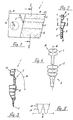
- the vehicle door shown schematically in FIG. 1 is intended to be a front, side door 1 of a passenger car (not shown further). It is hinged to the A-pillar of the vehicle body with its front door edge 1a by means of hinges which cannot be recognized.
- the vehicle door 1 which shows its inside, shows a fragment of a window frame 1b.
- the inside of the vehicle door is divided into a front section adjacent to the door edge 1a and a rear section.
- a crank 2 for lifting and lowering the window pane and a pulling and holding handle are arranged in the front section.
- the rear section of the inside of the door serves as padding and can be deformed while consuming energy. It essentially has three horizontally running parallel sections 4, 5 and 6. These sections 4, 5 and 6 are adjacent to an undetectable vehicle seat or a person taking a seat on it.
- the section 6 lies approximately at the level of the pelvic area of the vehicle occupant, the section 5 in the area of the abdomen and the section 4 finally in the area of the chest.
- this rear part of the inside of the vehicle consists of a one-piece deformation plate 7 designed as a hollow chamber structure, which has different hollow chamber profiles for the individual sections 4, 5, 6.
- the hollow chamber profile of section 6, which is assigned to the pelvic area of the vehicle occupant, is designed to be the stiffest.
- the stiffness of section 4 for the chest area is somewhat lower and, finally, section 5 for the abdomen area has the lowest stiffness.
- the number of the transverse webs 8 is intended to illustrate the degree of the respective rigidity in FIG. 2.
- the deformation plate 7 On the inside of the vehicle, the deformation plate 7 has a cover film 9, which conveys a pleasing appearance.
- a continuous hollow chamber can be seen in the area of section 5.
- this hollow chamber it is possible, as shown in FIG. 5, to stiffen this hollow chamber by means of a wave-shaped support part 10, which points with its wave crests to the vehicle occupant.
- this support part 10 has predetermined bending points 11 on its flanks.
- the lower rigidity in the abdomen area is made possible by long, easily deformable crosspieces 12.
- the carrier plate 7 ' is designed as a separate component to which a door inner paneling 13 is subsequently attached. In this construction, however, it must be ensured that the door inner panel 13 has sufficient strength to prevent the webs 12 from being able to penetrate through them before they break off.
- Such a deformation plate 7 enables a choice of material detached from the cladding 13. In addition, it allows greater freedom in the choice of its manufacturing process.
- FIG. 4 This is illustrated in FIG. 4.
- a molded body 15 recognizable from plastic, which is constructed symmetrically along the axis 16 and includes a deformation plate for the left door and a deformation plate for the right door.
- This molded body 15 has been produced by a blow molding process, and the two deformation plates are obtained by subsequent separation along the line 16. In this way, the deformation plates can be produced particularly cheaply.
Description
Die Erfindung bezieht sich auf eine seitliche Fahrzeugtür, insbesondere für Personenkraftwagen nach dem Oberbegriff des Hauptanspruchs (Siehe z.B die DE-A-2 409 619 oder die GB-A-1 441 598).The invention relates to a side vehicle door, especially for passenger cars according to the preamble of the main claim (see e.g. DE-A-2 409 619 or GB-A-1 441 598).
Bei einem Autounfall ist der Seitenaufprall für den Fahrzeuginsassen besonders kritisch. Die Stoßfront des gegnerischen Fahrzeuges dringt bei dieser Unfallart in die Tür ein und schiebt dabei sehr steife Einbauteile, wie Türöffnungs- und Fensterhebemechanismus vor sich her. Andererseits fällt durch die Beschleunigung des Aufpralls der Fahrzeuginsasse gegen die Türinnenseite und kann sich dabei erheblich durch die eindringenden Bauteile verletzen. Aus diesem Grunde werden Fahrzeugtüren an ihrer Innenseite gepolstert. Allerdings vermag die Polsterung heutiger Fahrzeuge nur geringe Kräfte aufzunehmen und vermindert das Verletzungsrisiko nicht wesentlich.In a car accident, the side impact is particularly critical for the vehicle occupant. The impact front of the opposing vehicle penetrates the door in this type of accident and pushes very stiff built-in parts, such as the door opening and window lifting mechanism. On the other hand, the acceleration of the impact of the vehicle occupant falls against the inside of the door and can thereby be seriously injured by the penetrating components. For this reason, vehicle doors are padded on the inside. However, the upholstery of today's vehicles can only absorb low forces and does not significantly reduce the risk of injury.
Einen Schritt weiter geht die DE-A- 2 409 619, die an der Türinnenseite im Bereich der Brüstung ein eingelagertes Deformationsglied vorsieht. Dieses Deformationsglied ist in der Lage, die Energie des auftreffenden Fahrzeuginsassen unter Verformung aufzuzehren, und damit die Beschleunigungswerte seines Körpers herabzusetzen. Allerdings ist die Ausgestaltung der Vorveröffentlichung nur im Brustbereich des Fahrzeuginsassen wirksam, während die übrigen Körperregionen nach wie vor dem erhöhten Verletzungsrisiko ausgesetzt sind.DE-A-2 409 619 goes one step further and provides an embedded deformation element on the inside of the door in the area of the parapet. This deformation element is able to absorb the energy of the impacting vehicle occupant under deformation, and thus reduce the acceleration values of his body. However, the design of the prior publication is only effective in the chest area of the vehicle occupant, while the other body regions are still exposed to the increased risk of injury.
Aufgrund seiner Anatomie weist der menschliche Körper Regionen unterschiedlicher Widerstandsfestigkeit auf. So vermögen die starken Beckenknochen erheblich größere Kräfte aufzunehmen ohne zu brechen als beispielsweise der Brustbereich. Besonders schwach in diesem Sinne ist der Abdomen- oder Bauchbereich ausgebildet, in dem sich Körperorgane ohne nennenswerten Skelettschutz befinden.Due to its anatomy, the human body has regions of different resistance. The strong pelvic bones are able to absorb considerably greater forces without breaking than the chest area, for example. The abdomen or abdominal area is particularly weak in this sense, in which there are organs without significant skeletal protection.
Die derzeitigen Polsterungen von Fahrzeugtürinnenseiten nehmen auf diese Besonderheiten keine Rücksicht, da sie auf der gesamten Fläche im wesentlichen mit gleicher Steifigkeit ausgelegt sind (Siehe auch z.B. die GB-A-1 441 598). Auch das Deformationsglied nach der genannten Vorveröffentlichung berücksichtigt nicht die unterschiedliche Widerstandsfähigkeit der einzelnen Körperregionen. Wie bereits ausgeführt, wirkt sie lediglich im Brustbereich.The current upholstery on the inside of the vehicle door does not take these special features into account, since they are designed with essentially the same rigidity over the entire surface (see also e.g. GB-A-1 441 598). The deformation element according to the aforementioned prior publication also does not take into account the different resilience of the individual body regions. As already stated, it only works in the chest area.
Aufgabe der Erfindung ist es, eine gattungsgemäße Fahrzeugtür so auszugestalten, daß die deformierbare Türinnenseite der Anatomie des menschlichen Körpers besser gerecht wird.The object of the invention is to design a generic vehicle door so that the deformable inside of the door better meets the anatomy of the human body.
Die Aufgabe wird erfindungsgemäß gelöst mit den Merkmalen des Hauptanspruchs. Weitere Ausgestaltungen der Erfindung ergeben sich aus den Unteransprüchen.The object is achieved with the features of the main claim. Further refinements of the invention result from the subclaims.
Die Innenseite, die als Polsterung dient, weist bei der erfindungsgemäßen Fahrzeugtür im wesentlichen drei deformierbare Abschnitte auf mit unterschiedlichen Steifigkeiten. Im ersten und unteren Abschnitt, der dem Becken des Fahrzeuginsassens benachbart liegt, ist die höchste Steifigkeit vorgesehen. Eine geringere Steifigkeit sieht der obere, dem Brustbereich des Fahrzeuginsassens nächstliegende Abschnitt vor. Schließlich ist der mittlere Bereich der Fahrzeuginnentür besonders weich ausgelegt, um den Abdomenbereich des Fahrzeuginsassens abfangen zu können.The inside, which serves as padding, has essentially three deformable sections with different stiffnesses in the vehicle door according to the invention. The highest stiffness is provided in the first and lower section, which is adjacent to the pelvis of the vehicle occupant. The upper section closest to the chest area of the vehicle occupant provides less rigidity. Finally, the middle area of the vehicle interior door is designed to be particularly soft in order to be able to intercept the abdomen area of the vehicle occupant.
In einer zweckmäßigen Ausgestaltung geht die Erfindung von der Überlegung aus, daß große Fahrzeuginsassen als Fahrer den Sitz weiter nach hinten verstellen gegenüber kleinen Fahrzeuginsassen. Außerdem ist im allgemeinen davon auszugehen, daß große Fahrzeuginsassen eine größere Masse aufweisen und damit bei einem Seitenaufprall mit höherer Kraft gegen die Türinnenseite geschleudert werden. Die Türinnenseite wird diesem Umstand dadurch gerecht, daß sich die deformierbaren Abschnitte zum hinteren Türrand hin in ihren Steifigkeiten erhöhen.In an expedient embodiment, the invention is based on the consideration that large vehicle occupants as the driver adjust the seat further back compared to small vehicle occupants. In addition, it can generally be assumed that large vehicle occupants have a larger mass and are therefore thrown against the inside of the door with greater force in the event of a side impact. The inside of the door does justice to this fact that the deformable sections increase their stiffness towards the rear door edge.
Als besonders vorteilhaft hat es sich erwiesen, die Innenseite als eine strukturierte Deformationsplatte auszulegen. Diese Deformationsplatte ist mit einer als Türinnenverkleidung dienenden Deckfolie versehen. Dabei kann die Deckfolie und die Deformationsplatte als einstückiges oder integriertes Formteil ausgebildet sein. In diesem Fall läßt sich diese Baueinheit besonders einfach als Kunststoffschaumteil herstellen.It has proven to be particularly advantageous to design the inside as a structured deformation plate. This deformation plate is provided with a cover film which serves as the interior door lining. The cover film and the deformation plate can be designed as a one-piece or integrated molded part. In this case, this unit can be produced particularly easily as a plastic foam part.
Es könnte doch auch zweckmäßig sein, die Deformationsplatte als getrenntes Bauteil auszulegen, das sich beispielsweise im Blasverfahren als Kunststoffteil herstellen läßt. Wählt man dieses Herstellungsverfahren, besteht die Möglichkeit, bei entsprechender Gestaltung in einem Arbeitsgang sowohl die Deformationsplatte für die linke als auch für die rechte Fahrzeugtür aufzuformen.It could also be expedient to design the deformation plate as a separate component that can be produced, for example, in a blowing process as a plastic part. If one chooses this manufacturing process, it is possible, with the appropriate design, to mold both the deformation plate for the left and for the right vehicle door in one work step.
Ungeachtet der einzelnen Herstellungsmöglichkeiten kann das Formteil, je nach Anforderung, in allen gängigen Materialien, wie Thermoplaste, Aluminium, Kohle- und Polyamidfaser verstärkte Harze usw. ausgeführt sein.Regardless of the individual manufacturing possibilities, the molded part can, depending on requirements, be made in all common materials, such as thermoplastics, aluminum, carbon and polyamide fiber reinforced resins, etc.
Zweckmäßigerweise weist die Deformationsplatte eine Hohlkammerstruktur auf, deren Hohlkammerquerschnitte sich rechteckig, kreisförmig, elliptisch, dreieckig, rautenförmig usw. ausbilden lassen. Die Form des Hohlkörperquerschnitts richtet sich dabei wiederum allein nach den jeweils gestellten Anforderungen. Durch die Verwendung einer Hohlkammerstruktur lassen sich die benötigten Steifigkeiten über die Aussparungen abstimmen. Dabei gleicht das Kraft-Weg-Verhalten von Hohlkammerstrukturen einer konstanten Kennung, wodurch eine optimale Energieaufnahme über einen großen Verformungsweg gewährleistet ist. Im Gegensatz zu einem völlig ausgeschäumten Polster gehen Hohlkammerstrukturen erst bei sehr großen Umformungsgraden auf Block. Desweiteren läßt sich die Hohlkammerstruktur im Vergleich zu einer Vollschaumausführung leichter und billiger ausführen. Darüber hinaus verschaffen Hohlkammerstrukturen bei entsprechender Auslegung Platz für die Türeinbauteile, wie Fensterheber usw.The deformation plate expediently has a hollow chamber structure, the hollow chamber cross sections of which can be formed rectangular, circular, elliptical, triangular, diamond-shaped, etc. The shape of the hollow body cross-section in turn depends solely on the particular requirements. By using a hollow chamber structure, the required stiffness can be coordinated with the recesses. The force-displacement behavior of hollow chamber structures is similar to a constant identifier, which ensures optimal energy absorption over a large deformation path. In contrast to a completely foamed upholstery, hollow chamber structures only go into block at very high degrees of deformation. Furthermore, the hollow chamber structure can be compared to one Make the full foam version lighter and cheaper. In addition, if designed appropriately, hollow chamber structures provide space for the door components, such as window regulators, etc.
Schließlich läßt sich durch definierte Soll-Knickstellen in den einzelnen Kammerwänden des Hohlprofils das Deformationsverhalten der Türinnenseite noch genauer einstellen.Finally, the deformation behavior of the inside of the door can be set even more precisely by means of defined nominal kinks in the individual chamber walls of the hollow profile.
Weitere vorteilhafte Ausgestaltungen der Erfindung ergeben sich aus der nachfolgenden Beschreibung mehrerer Ausführungsbeispiele und der dazugehörigen Zeichnung. Es zeigt:
- Fig. 1
- eine seitliche Fahrzeugtür von innen gesehen;
- Fig. 2
- die Fahrzeugtür im Schnitt II-II nach Fig. 1;
- Fig. 3
- eine ähnliche Schnittdarstellung wie Fig. 2 einer weiteren Ausgestaltung einer Fahrzeugtür in vergrößertem Maßstab;
- Fig. 4
- die einheitliche Ausgestaltung einer Deformationsplatte für die linke und rechte Fahrzeugtür und
- Fig. 5
- ein Stützteil in der Hohlkammerstruktur mit Soll-Knickstellen entsprechend dem Schnitt V-V nach Fig. 2.
- Fig. 1
- a side vehicle door seen from the inside;
- Fig. 2
- the vehicle door in section II-II of FIG. 1;
- Fig. 3
- a sectional view similar to Figure 2 of a further embodiment of a vehicle door on an enlarged scale.
- Fig. 4
- the uniform design of a deformation plate for the left and right vehicle doors and
- Fig. 5
- a support part in the hollow chamber structure with predetermined kinks according to the section VV of FIG. 2nd
Die in Fig. 1 schematisch dargestellte Fahrzeugtür soll eine vordere, seitliche Tür 1 eines nicht weiter dargestellten Personenkraftwagens sein. Sie ist dabei über nicht erkennbare Scharniere mit ihrem vorderen Türrand 1a an der A-Säule der Fahrzeugkarosserie angelenkt. Außerdem läßt die Fahrzeugtür 1, die ihre Innenseite zeigt, bruchstückhaft einen Fensterrahmen 1b erkennen.The vehicle door shown schematically in FIG. 1 is intended to be a front, side door 1 of a passenger car (not shown further). It is hinged to the A-pillar of the vehicle body with its front door edge 1a by means of hinges which cannot be recognized. In addition, the vehicle door 1, which shows its inside, shows a fragment of a window frame 1b.
Die Innenseite der Fahrzeugtür ist aufgeteilt in einen vorderen, dem Türrand 1a benachbarten Abschnitt und einen hinteren Abschnitt. Im vorderen Abschnitt sind eine Kurbel 2 für das Heben und Senken der Fensterscheibe und ein Zuzieh- und Haltegriff angeordnet. Der hintere Abschnitt der Türinnenseite dient als Polsterung und läßt sich unter Energieverzehr deformieren. Er weist im wesentlichen drei horizontal verlaufende parallele Abschnitte 4, 5 und 6 auf. Diese Abschnitte 4, 5 und 6 liegen benachbart eines nicht erkennbaren Fahrzeugsitzes bzw. einer darauf Platz nehmenden Person. Dabei liegt der Abschnitt 6 in etwa in der Höhe des Beckenbereichs des Fahrzeuginsassen, der Abschnitt 5 im Bereich des Abdomens und der Abschnitt 4 schließlich im Bereich der Brust.The inside of the vehicle door is divided into a front section adjacent to the door edge 1a and a rear section. In the front section, a crank 2 for lifting and lowering the window pane and a pulling and holding handle are arranged. The rear section of the inside of the door serves as padding and can be deformed while consuming energy. It essentially has three horizontally running
Wie Fig. 2 zeigt, besteht dieser hintere Teil der Fahrzeuginnenseite aus einer einstückigen, als Hohlkammerstruktur ausgebildeten Deformationsplatte 7, die für die einzelnen Abschnitte 4, 5, 6 unterschiedliche Hohlkammerprofile aufweist. Dabei ist das Hohlkammerprofil des Abschnitts 6, das dem Beckenbereich des Fahrzeuginsassens zugeordnet ist, am steifesten ausgelegt. Die Steifigkeit des Abschnittes 4 für den Brustbereich liegt demgegenüber etwas niedriger und schließlich hat der Abschnitt 5 für den Abdomenbereich die geringste Steifigkeit. Den Grad der jeweiligen Steifigkeit sollen in Fig. 2 die Anzahl der Querstege 8 verdeutlichen. Zur Fahrzeuginnenseite weist die Deformationsplatte 7 eine Deckfolie 9 auf, die ein gefälliges Aussehen vermittelt.As shown in FIG. 2, this rear part of the inside of the vehicle consists of a one-piece deformation plate 7 designed as a hollow chamber structure, which has different hollow chamber profiles for the
Nach Fig. 2 ist im Bereich des Abschnittes 5 eine durchgehende Hohlkammer erkennbar. Es ist jedoch möglich, wie Fig. 5 zeigt, diese Hohlkammer durch ein wellenförmiges Stützteil 10 zu versteifen, das mit seinen Wellenbergen zum Fahrzeuginsassen zeigt. Für ein definiertes Verformungsverhalten weist dieses Stützteil 10 an seinen Flanken Soll-Knickstellen 11 auf.2, a continuous hollow chamber can be seen in the area of
Die Innenseite der Fahrzeugtür 1' nach Fig. 3, von der auch abschnittsweise ein Türaußenblech 14 angedeutet ist, hat einen etwas anderen Aufbau. Zunächst einmal wird die geringere Steifigkeit im Abdomenbereich durch lange leicht verformbare Querstege 12 ermöglicht. Des weiteren ist die Trägerplatte 7' als getrenntes Bauteil ausgelegt, an dem nachträglich eine Türinnenverkleidung 13 befestigt wird. Bei diesem Aufbau ist jedoch darauf zu achten, daß die Türinnenverkleidung 13 eine ausreichende Festigkeit aufweist, um zu verhindern, daß die Stege 12, bevor sie abbrechen, durch sie hindruchstoßen können. Eine derartige Deformationsplatte 7 ermöglicht eine Materialwahl losgelöst von der Verkleidung 13. Außerdem läßt sie eine größere Freiheit in der Wahl ihres Herstellungsverfahrens zu.The inside of the vehicle door 1 'according to FIG. 3, of which an
In Fig. 4 wird dies verdeutlicht. Hier ist ein Formkörper 15; aus Kunststoff erkennbar, der entlang der Achse 16 symmetrisch aufgebaut ist und eine Deformationsplatte für die linke Tür und eine Deformationsplatte für die rechte Tür beinhaltet. Dieser Formkörper 15 ist durch ein Blasformverfahren hergestellt worden, und durch nachträgliches Trennen entlang der Linie 16 werden die beiden Deformationsplatten erhalten. Auf diese Weise lassen sich die Deformationsplatten besonders günstig herstellen.This is illustrated in FIG. 4. Here is a molded
Claims (7)
- A side vehicle door, in particular for passenger vehicles, the inner side of which, facing a vehicle seat, is designed so as to be deformable in the case of impact of the body of an occupant of the vehicle seat, at least in sections, under energy dissipation, characterised in that the rigidity of the energy-dissipating sections (4, 5, 6) is adapted to the differing capacity for resistance of the individual areas of the body of the occupant of the vehicle adjacent thereto, and in the abdominal area of the occupant of the vehicle has lower values and in the pelvic and chest areas has higher values.
- A vehicle door according to Claim 1, with a vehicle seat which is adjustable in longitudinal direction of the vehicle, characterised in that the differing rigidities of the inner side increase towards the rear rim of the door.
- A vehicle door according to Claim 1 or 2, characterised in that the inner side of the vehicle door (1) is constructed as a structured deformation plate (7, 7') lined with a cover film (9).
- A vehicle door according to Claim 3, characterised in that the inner side is formed by an integrated shaped part.
- A vehicle door according to Claim 3, characterised in that the deformation plate (7') is provided as a separate component from the cover film (9).
- A vehicle door according to one of Claims 4 or 5, characterised in that the deformation plate (7,7') has a hollow chambered structure.
- A vehicle door according to Claim 6, characterised in that the hollow-chambered structure provides a support piece (10) with defined nominal break sites (11).
Applications Claiming Priority (2)
| Application Number | Priority Date | Filing Date | Title |
|---|---|---|---|
| DE19863615436 DE3615436A1 (en) | 1986-05-07 | 1986-05-07 | SIDE VEHICLE DOOR |
| DE3615436 | 1986-05-07 |
Publications (3)
| Publication Number | Publication Date |
|---|---|
| EP0244579A2 EP0244579A2 (en) | 1987-11-11 |
| EP0244579A3 EP0244579A3 (en) | 1989-11-29 |
| EP0244579B1 true EP0244579B1 (en) | 1991-06-12 |
Family
ID=6300339
Family Applications (1)
| Application Number | Title | Priority Date | Filing Date |
|---|---|---|---|
| EP87102551A Expired - Lifetime EP0244579B1 (en) | 1986-05-07 | 1987-02-24 | Side vehicle door |
Country Status (3)
| Country | Link |
|---|---|
| US (1) | US4786100A (en) |
| EP (1) | EP0244579B1 (en) |
| DE (2) | DE3615436A1 (en) |
Cited By (1)
| Publication number | Priority date | Publication date | Assignee | Title |
|---|---|---|---|---|
| DE102008033623A1 (en) | 2008-07-17 | 2010-01-21 | Volkswagen Ag | Door inner module for vehicle side door, comprises inner cladding part which has recess for storage compartment, and attachment part has functional area, where deformation structure is integrated in functional area |
Families Citing this family (56)
| Publication number | Priority date | Publication date | Assignee | Title |
|---|---|---|---|---|
| US4890877A (en) * | 1988-07-12 | 1990-01-02 | General Motors Corporation | Energy absorption system for vehicle door and method of making |
| DE4020309A1 (en) * | 1989-06-27 | 1991-01-10 | Mazda Motor | IMPACT ENERGY ABSORBING CONSTRUCTION FOR VEHICLES |
| JPH0349110U (en) * | 1989-09-20 | 1991-05-13 | ||
| US5040335A (en) * | 1991-03-18 | 1991-08-20 | Davidson Textron Inc. | Inner panel assembly with integral energy absorber |
| CH684834A5 (en) * | 1991-08-12 | 1995-01-13 | Alusuisse Lonza Services Ag | Impact carrier for vehicle doors. |
| JP3127667B2 (en) * | 1992-07-02 | 2001-01-29 | トヨタ自動車株式会社 | Door trim shock absorbing structure |
| JPH0625015U (en) * | 1992-09-04 | 1994-04-05 | 三ツ星ベルト株式会社 | Impact resistant automotive door trim |
| US5290087A (en) * | 1992-10-19 | 1994-03-01 | Prince Corporation | Armrest with impact dependent dimension |
| US5395135A (en) * | 1992-11-02 | 1995-03-07 | Ford Motor Company | Energy absorbing vehicle door and side panels |
| FR2720983B1 (en) † | 1994-06-08 | 1996-08-02 | Plasto Sa | Double wall composite trim for automotive. |
| US5636866A (en) * | 1994-09-21 | 1997-06-10 | Kojima Press Industry Co., Ltd. | Shock absorbing structure for motor vehicle |
| DE4441777C2 (en) * | 1994-11-24 | 2002-11-28 | Holm Singer | Method for impact energy absorption and space enlargement for vehicles (CIS) and device therefor |
| US5577794A (en) * | 1994-12-12 | 1996-11-26 | General Motors Corporation | Push-out target vehicle side door |
| US5482344A (en) * | 1994-12-23 | 1996-01-09 | Ford Motor Company | Deployable vehicle door trim panel |
| US5536060A (en) * | 1995-02-17 | 1996-07-16 | General Motors Corporation | Reinforced vehicle door |
| US5641195A (en) * | 1995-04-05 | 1997-06-24 | Ford Motor Company | Trim component having energy absorbing feature |
| US5549349A (en) * | 1995-05-01 | 1996-08-27 | Chrysler Corporation | Side impact protection system |
| US5588692A (en) * | 1995-10-11 | 1996-12-31 | General Motors Corporation | Push-out vehicle side door |
| US5709407A (en) * | 1995-10-13 | 1998-01-20 | Chrysler Corporation | Energy absorbing vehicle trim molding |
| US5603548A (en) * | 1995-10-16 | 1997-02-18 | General Motors Corporation | Push-out vehicle side door |
| JP3186563B2 (en) * | 1996-01-31 | 2001-07-11 | トヨタ自動車株式会社 | Impact energy absorbing member |
| US5795013A (en) * | 1996-06-20 | 1998-08-18 | Honda Giken Kogyo Kabushiki Kaisha | Energy absorbing trim, and methods of constructing and utilizing same |
| CA2182542A1 (en) * | 1996-08-01 | 1998-02-02 | Koichi Yoshino | Shock absorbing wall construction |
| FR2758115B1 (en) * | 1997-01-08 | 1999-04-02 | Rockwell Lvs | VEHICLE DOOR WITH PASSENGER PUSH-BUTTON FOR PASSENGER SAFETY |
| US6056349A (en) * | 1997-06-09 | 2000-05-02 | Aluminum Company Of America | Vehicle door having improved side crash resistance and associated method |
| JP3285141B2 (en) * | 1997-11-19 | 2002-05-27 | 河西工業株式会社 | Automotive interior parts and method of manufacturing the same |
| JPH11334506A (en) * | 1998-05-26 | 1999-12-07 | Toyota Motor Corp | Shock absorbing structure for vehicle door |
| US6149853A (en) * | 1998-08-03 | 2000-11-21 | Visteon Global Technologies, Inc. | Method for manufacturing interior door panels having concealed voids at the junction of integrally molded energy absorbers |
| US5944373A (en) * | 1998-08-18 | 1999-08-31 | Aluminum Company Of America | Lightweight tailgate assembly |
| US6049952A (en) * | 1998-09-10 | 2000-04-18 | Chrysler Corporation | Energy absorbing trim component fastening system |
| DE19846419A1 (en) * | 1998-10-08 | 2000-04-13 | Volkswagen Ag | Module, for the inside of a vehicle door, consists of a hard material inner lining with a cut-out and an insert |
| US6164716A (en) * | 1998-12-18 | 2000-12-26 | Daimlerchrysler Corporation | Energy dissipating body panel assembly |
| US20010054814A1 (en) * | 1999-12-10 | 2001-12-27 | Bridgestone Corporation | Impact absorbing member and head protective member |
| JP3873565B2 (en) * | 2000-02-29 | 2007-01-24 | マツダ株式会社 | Automotive door |
| US6550846B1 (en) | 2002-06-05 | 2003-04-22 | Ford Global Technologies, Inc. | Aluminum automotive door assembly |
| US6672642B1 (en) | 2002-06-11 | 2004-01-06 | Alcoa Inc. | Hybrid tailgate |
| US6983967B2 (en) * | 2002-08-12 | 2006-01-10 | Leon Plastics, Inc. | Armrest with side impact resistance feature |
| US20060261635A1 (en) * | 2005-05-23 | 2006-11-23 | Jay Winborn | Automobile door assemblies |
| US7222910B1 (en) | 2005-08-30 | 2007-05-29 | Ford Global Technologies, Llc | Multi-function armrest for automotive vehicle |
| US7708313B2 (en) * | 2005-09-01 | 2010-05-04 | International Automotive Components Group North America, Inc. | Plastic basket countermeasure for door side impact |
| US7357444B2 (en) * | 2006-03-06 | 2008-04-15 | International Automotive Components Group North America, Inc. | Tunable geometry for energy absorbing foam to lower peak load during side impact |
| US20070222256A1 (en) * | 2006-03-23 | 2007-09-27 | Jeffrey Valentage | Hybrid door core and trim module with integrated components |
| US20070267889A1 (en) * | 2006-03-23 | 2007-11-22 | Flendrig Joseph G M | Door assembly with core module having integrated belt line reinforcement |
| US20070222257A1 (en) * | 2006-03-23 | 2007-09-27 | Joseph Gustaaf Marie Flendrig | Core module for door assembly having integrated reinforcements |
| US20070220811A1 (en) * | 2006-03-23 | 2007-09-27 | Joseph Gustaaf Marie Flendrig | Door assembly with integrated window sealing system |
| WO2007111787A1 (en) * | 2006-03-23 | 2007-10-04 | Exxonmobil Chemical Patents Inc. | Door core module |
| US20070220812A1 (en) * | 2006-03-23 | 2007-09-27 | Jeffrey Valentage | Door core module |
| US20070222249A1 (en) * | 2006-03-23 | 2007-09-27 | Jeffrey Valentage | Interior trim panel with integrated living hinged components |
| US8152218B2 (en) * | 2008-05-13 | 2012-04-10 | Ford Global Technologies, Llc | Integral pelvic impact energy-absorbing pre-crush protective construction for vehicle door |
| WO2010135442A2 (en) * | 2009-05-19 | 2010-11-25 | Inteva Products Llc. | Carrier supported pull-cup |
| FR2971189B1 (en) * | 2011-02-03 | 2014-10-24 | Eurostyle Systems | EQUIPMENT PIECE WITH SOFT SPRING |
| JP5983043B2 (en) * | 2012-05-30 | 2016-08-31 | ブラザー工業株式会社 | Image reading apparatus and cutting apparatus |
| US9193247B2 (en) * | 2012-10-05 | 2015-11-24 | Ford Global Technologies, Llc | Vehicle door trim panel shut face feature to reduce deflection |
| JP6156291B2 (en) * | 2014-09-01 | 2017-07-05 | トヨタ自動車株式会社 | Vehicle door structure |
| US10093263B2 (en) * | 2015-07-16 | 2018-10-09 | Ford Global Technologies, Llc | Energy absorbing instrument panel component |
| US10336276B2 (en) | 2017-01-05 | 2019-07-02 | Ford Global Technologies, Llc | Energy absorber with varying stiffness |
Family Cites Families (15)
| Publication number | Priority date | Publication date | Assignee | Title |
|---|---|---|---|---|
| DE2127724C3 (en) * | 1971-06-04 | 1975-06-05 | Ford-Werke Ag, 5000 Koeln | Vehicle door, in particular for passenger vehicles |
| DE2158709A1 (en) * | 1971-11-26 | 1973-05-30 | Daimler Benz Ag | DOOR FOR PASSENGER CARS |
| GB1372752A (en) * | 1972-01-11 | 1974-11-06 | Chrysler Uk | Vehicle doors |
| AU470440B2 (en) * | 1973-02-28 | 1976-03-18 | Nissan Motor Company Limited | Vehicle door |
| GB1441598A (en) * | 1973-11-27 | 1976-07-07 | Ford Motor Co | Vehicle side impact protection |
| DE2426705C2 (en) * | 1974-06-01 | 1985-04-25 | Daimler-Benz Ag, 7000 Stuttgart | Door for vehicles, in particular for passenger cars |
| FR2273690A1 (en) * | 1974-06-04 | 1976-01-02 | British Leyland Uk Ltd | MEANS FOR ABSORBING ENERGY, INTENDED TO BE PLACED INSIDE VEHICLES TO PROTECT PASSENGERS IN THE EVENT OF A SHOCK |
| DE2724017A1 (en) * | 1977-05-27 | 1978-12-07 | Daimler Benz Ag | EDGE PROTECTION OF VEHICLES |
| FR2424825A1 (en) * | 1978-05-03 | 1979-11-30 | Renault | Vehicle side door - has hollow beams on inside at levels of thorax and pelvis to provide reinforcement |
| JPS5520A (en) * | 1978-05-12 | 1980-01-05 | Kureha Chem Ind Co Ltd | Production of peptide |
| JPS6044187B2 (en) * | 1979-09-08 | 1985-10-02 | 日産自動車株式会社 | Automotive plate material and its manufacturing method |
| JPS5647319A (en) * | 1979-09-21 | 1981-04-30 | Wako Chem Kk | Preparation of formed door panel for motorcar |
| DE3425777C2 (en) * | 1984-07-13 | 1986-10-02 | Daimler-Benz Ag, 7000 Stuttgart | Car door |
| DE3500392A1 (en) * | 1985-01-08 | 1986-07-10 | Gebr. Happich Gmbh, 5600 Wuppertal | UPHOLSTERY BODY FOR THE INTERIOR OF VEHICLES |
| JPS61207252A (en) * | 1985-03-12 | 1986-09-13 | Mazda Motor Corp | Knee protector for automobile |
-
1986
- 1986-05-07 DE DE19863615436 patent/DE3615436A1/en not_active Withdrawn
-
1987
- 1987-02-24 DE DE8787102551T patent/DE3770692D1/en not_active Expired - Lifetime
- 1987-02-24 EP EP87102551A patent/EP0244579B1/en not_active Expired - Lifetime
- 1987-05-07 US US07/046,688 patent/US4786100A/en not_active Expired - Fee Related
Non-Patent Citations (1)
| Title |
|---|
| Patent Abstracts of Japan, Band 5, N. 105 (M-77)(777), 8. Juli 1981 * |
Cited By (2)
| Publication number | Priority date | Publication date | Assignee | Title |
|---|---|---|---|---|
| DE102008033623A1 (en) | 2008-07-17 | 2010-01-21 | Volkswagen Ag | Door inner module for vehicle side door, comprises inner cladding part which has recess for storage compartment, and attachment part has functional area, where deformation structure is integrated in functional area |
| DE102008033623B4 (en) * | 2008-07-17 | 2020-10-08 | Volkswagen Ag | Inner door module for a vehicle side door |
Also Published As
| Publication number | Publication date |
|---|---|
| EP0244579A3 (en) | 1989-11-29 |
| US4786100A (en) | 1988-11-22 |
| DE3615436A1 (en) | 1987-11-12 |
| EP0244579A2 (en) | 1987-11-11 |
| DE3770692D1 (en) | 1991-07-18 |
Similar Documents
| Publication | Publication Date | Title |
|---|---|---|
| EP0244579B1 (en) | Side vehicle door | |
| EP0968889B2 (en) | Instrument panel | |
| DE19531982B4 (en) | Body structure for a motor vehicle | |
| DE19609945B4 (en) | Armrest assembly and armrest support for a vehicle door | |
| EP2018999B1 (en) | Energy absorber for use as collision protection in a motor vehicle | |
| DE4326270A1 (en) | Motor vehicle with a rigid floor structure | |
| DE19807581A1 (en) | Energy-absorbing device for vehicle seat | |
| DE2158709A1 (en) | DOOR FOR PASSENGER CARS | |
| DE3127172A1 (en) | DASHBOARD FOR A MOTOR VEHICLE | |
| DE3607855A1 (en) | Passenger cell of a motor vehicle | |
| DE19632488A1 (en) | Passenger motor vehicle with frame | |
| DE19721607A1 (en) | Side impact protection | |
| EP2585359B1 (en) | Body of a vehicle having a floor with a transverse extruded profile | |
| EP1300323A2 (en) | Vehicle body element with a large surface | |
| DE19945590B4 (en) | Body for a motor vehicle | |
| EP0806324B1 (en) | Motor vehicle door with side impact protection | |
| DE10032556A1 (en) | Vehicle body component in sandwich construction is compact unit enclosing passenger cell, with outer and inner skins, and internal stiffening structure and distance elements | |
| EP0031131B1 (en) | Utility vehicle with a capsule for the receipt of a driving mechanism, essentially aranged inside the driver's cab outline | |
| DE102020102612B4 (en) | Door assembly for a motor vehicle | |
| DE19501454A1 (en) | Vehicle door with protective anti=collision member | |
| DE69735544T2 (en) | SOUND ABSORPTION LAYER WITH INTEGRAL RIBBON STRUCTURE | |
| EP1608537B1 (en) | Shock-absorbing covering element for the interior of motor vehicles | |
| DE19840728B4 (en) | Headrest and method of making same | |
| DE19517782C1 (en) | Instrument panel for interior of motor vehicle | |
| DE102009005101B4 (en) | Safety device for a vehicle |
Legal Events
| Date | Code | Title | Description |
|---|---|---|---|
| PUAI | Public reference made under article 153(3) epc to a published international application that has entered the european phase |
Free format text: ORIGINAL CODE: 0009012 |
|
| AK | Designated contracting states |
Kind code of ref document: A2 Designated state(s): DE FR GB IT SE |
|
| PUAL | Search report despatched |
Free format text: ORIGINAL CODE: 0009013 |
|
| AK | Designated contracting states |
Kind code of ref document: A3 Designated state(s): DE FR GB IT SE |
|
| 17P | Request for examination filed |
Effective date: 19891021 |
|
| 17Q | First examination report despatched |
Effective date: 19901129 |
|
| GRAA | (expected) grant |
Free format text: ORIGINAL CODE: 0009210 |
|
| AK | Designated contracting states |
Kind code of ref document: B1 Designated state(s): DE FR GB IT SE |
|
| ET | Fr: translation filed | ||
| GBT | Gb: translation of ep patent filed (gb section 77(6)(a)/1977) | ||
| REF | Corresponds to: |
Ref document number: 3770692 Country of ref document: DE Date of ref document: 19910718 |
|
| ITF | It: translation for a ep patent filed |
Owner name: STUDIO JAUMANN |
|
| PLBE | No opposition filed within time limit |
Free format text: ORIGINAL CODE: 0009261 |
|
| STAA | Information on the status of an ep patent application or granted ep patent |
Free format text: STATUS: NO OPPOSITION FILED WITHIN TIME LIMIT |
|
| 26N | No opposition filed | ||
| EAL | Se: european patent in force in sweden |
Ref document number: 87102551.6 |
|
| PGFP | Annual fee paid to national office [announced via postgrant information from national office to epo] |
Ref country code: SE Payment date: 19970203 Year of fee payment: 11 |
|
| PGFP | Annual fee paid to national office [announced via postgrant information from national office to epo] |
Ref country code: DE Payment date: 19970210 Year of fee payment: 11 |
|
| PGFP | Annual fee paid to national office [announced via postgrant information from national office to epo] |
Ref country code: GB Payment date: 19970217 Year of fee payment: 11 |
|
| PGFP | Annual fee paid to national office [announced via postgrant information from national office to epo] |
Ref country code: FR Payment date: 19970228 Year of fee payment: 11 |
|
| PG25 | Lapsed in a contracting state [announced via postgrant information from national office to epo] |
Ref country code: GB Free format text: LAPSE BECAUSE OF NON-PAYMENT OF DUE FEES Effective date: 19980224 |
|
| PG25 | Lapsed in a contracting state [announced via postgrant information from national office to epo] |
Ref country code: SE Free format text: LAPSE BECAUSE OF NON-PAYMENT OF DUE FEES Effective date: 19980225 |
|
| PG25 | Lapsed in a contracting state [announced via postgrant information from national office to epo] |
Ref country code: FR Free format text: THE PATENT HAS BEEN ANNULLED BY A DECISION OF A NATIONAL AUTHORITY Effective date: 19980228 |
|
| GBPC | Gb: european patent ceased through non-payment of renewal fee |
Effective date: 19980224 |
|
| EUG | Se: european patent has lapsed |
Ref document number: 87102551.6 |
|
| PG25 | Lapsed in a contracting state [announced via postgrant information from national office to epo] |
Ref country code: DE Free format text: LAPSE BECAUSE OF NON-PAYMENT OF DUE FEES Effective date: 19981103 |
|
| REG | Reference to a national code |
Ref country code: FR Ref legal event code: ST |
|
| PG25 | Lapsed in a contracting state [announced via postgrant information from national office to epo] |
Ref country code: IT Free format text: LAPSE BECAUSE OF NON-PAYMENT OF DUE FEES;WARNING: LAPSES OF ITALIAN PATENTS WITH EFFECTIVE DATE BEFORE 2007 MAY HAVE OCCURRED AT ANY TIME BEFORE 2007. THE CORRECT EFFECTIVE DATE MAY BE DIFFERENT FROM THE ONE RECORDED. Effective date: 20050224 |