EP0244521B1 - Anlasser für Verbrennungsmotor - Google Patents
Anlasser für Verbrennungsmotor Download PDFInfo
- Publication number
- EP0244521B1 EP0244521B1 EP86303445A EP86303445A EP0244521B1 EP 0244521 B1 EP0244521 B1 EP 0244521B1 EP 86303445 A EP86303445 A EP 86303445A EP 86303445 A EP86303445 A EP 86303445A EP 0244521 B1 EP0244521 B1 EP 0244521B1
- Authority
- EP
- European Patent Office
- Prior art keywords
- starter
- contact
- coil
- bimetallic element
- temperature sensor
- Prior art date
- Legal status (The legal status is an assumption and is not a legal conclusion. Google has not performed a legal analysis and makes no representation as to the accuracy of the status listed.)
- Expired
Links
Images

Classifications
-
- F—MECHANICAL ENGINEERING; LIGHTING; HEATING; WEAPONS; BLASTING
- F02—COMBUSTION ENGINES; HOT-GAS OR COMBUSTION-PRODUCT ENGINE PLANTS
- F02N—STARTING OF COMBUSTION ENGINES; STARTING AIDS FOR SUCH ENGINES, NOT OTHERWISE PROVIDED FOR
- F02N11/00—Starting of engines by means of electric motors
- F02N11/08—Circuits specially adapted for starting of engines
- F02N11/087—Details of the switching means in starting circuits, e.g. relays or electronic switches
-
- F—MECHANICAL ENGINEERING; LIGHTING; HEATING; WEAPONS; BLASTING
- F02—COMBUSTION ENGINES; HOT-GAS OR COMBUSTION-PRODUCT ENGINE PLANTS
- F02N—STARTING OF COMBUSTION ENGINES; STARTING AIDS FOR SUCH ENGINES, NOT OTHERWISE PROVIDED FOR
- F02N15/00—Other power-operated starting apparatus; Component parts, details, or accessories, not provided for in, or of interest apart from groups F02N5/00 - F02N13/00
-
- H—ELECTRICITY
- H01—ELECTRIC ELEMENTS
- H01F—MAGNETS; INDUCTANCES; TRANSFORMERS; SELECTION OF MATERIALS FOR THEIR MAGNETIC PROPERTIES
- H01F27/00—Details of transformers or inductances, in general
- H01F27/40—Structural association with built-in electric component, e.g. fuse
- H01F27/402—Association of measuring or protective means
-
- H—ELECTRICITY
- H01—ELECTRIC ELEMENTS
- H01H—ELECTRIC SWITCHES; RELAYS; SELECTORS; EMERGENCY PROTECTIVE DEVICES
- H01H1/00—Contacts
- H01H1/50—Means for increasing contact pressure, preventing vibration of contacts, holding contacts together after engagement, or biasing contacts to the open position
- H01H1/504—Means for increasing contact pressure, preventing vibration of contacts, holding contacts together after engagement, or biasing contacts to the open position by thermal means
-
- F—MECHANICAL ENGINEERING; LIGHTING; HEATING; WEAPONS; BLASTING
- F02—COMBUSTION ENGINES; HOT-GAS OR COMBUSTION-PRODUCT ENGINE PLANTS
- F02N—STARTING OF COMBUSTION ENGINES; STARTING AIDS FOR SUCH ENGINES, NOT OTHERWISE PROVIDED FOR
- F02N11/00—Starting of engines by means of electric motors
- F02N11/10—Safety devices
-
- F—MECHANICAL ENGINEERING; LIGHTING; HEATING; WEAPONS; BLASTING
- F02—COMBUSTION ENGINES; HOT-GAS OR COMBUSTION-PRODUCT ENGINE PLANTS
- F02N—STARTING OF COMBUSTION ENGINES; STARTING AIDS FOR SUCH ENGINES, NOT OTHERWISE PROVIDED FOR
- F02N2200/00—Parameters used for control of starting apparatus
- F02N2200/06—Parameters used for control of starting apparatus said parameters being related to the power supply or driving circuits for the starter
- F02N2200/066—Relay temperature
-
- H—ELECTRICITY
- H01—ELECTRIC ELEMENTS
- H01F—MAGNETS; INDUCTANCES; TRANSFORMERS; SELECTION OF MATERIALS FOR THEIR MAGNETIC PROPERTIES
- H01F27/00—Details of transformers or inductances, in general
- H01F27/40—Structural association with built-in electric component, e.g. fuse
- H01F27/402—Association of measuring or protective means
- H01F2027/406—Temperature sensor or protection
Definitions
- the present invention relates to a starter for an internal combustion engine.
- the JOURNAL OF NIPPONDENSO TECHNICAL DISCLOSURE, No. 36-070, published July 15, 1984 discloses an engine starter that has a self-heating bimetallic element connected electrically in series to a starter switch and to be moved into contact with a first stationary contact electrically connected to a point between attracting and holding coils which form exciting coils for a plunger.
- the starter switch is connected to an electrical power source formed by a battery.
- the bimetallic element is heated to a predetermined temperature level sufficient to cause the bimetallic element to snap away from the first stationary contact into electrical contact with a second stationary contact which is grounded through a resistor.
- the starter requires two stationary contacts i.e. the first and second contacts associated with the bimetallic element. This disadvantageously increases the size of the temperature sensor formed by the bimetallic unit.
- One object of the present invention is to eliminate these problems and shortcomings.
- a starter for an internal combustion engine having a ring gear comprising a starter switch electrically connected to an electrical power source; a pinion axially movable into and out of meshing engagement with the ring gear; a plunger for moving the pinion towards the ring gear and having a first movable contact at one end; first and second stationary contacts both so positioned as to be contacted by the first movable contact; exciting coil means for moving the plunger towards the first and second stationary contacts, the exciting coil means comprising a first holding coil and a second attracting coil; a starter motor adapted to be energised when the first contact is moved into contact with the first and second stationary contacts forming an electrical connection therebetween, the starter motor being drivingly connected to the pinion; and a temperature sensor for detecting the temperature of one of the first and second coils; characterised in that the first and second coils have windings electrically connected in series at their one ends; a relay includes normally open contacts electrically connected in series to the electrical power source
- the bimetallic element of the temperature sensor is disposed adjacent one of the first and second coils of the plunger exciting coil means.
- the temperature sensor is electrically connected in series to the relay coil and the ground.
- an engine starter includes a motor 13 having an armature 13a mounted on a shaft 14 for rotation therewith.
- the shaft 14 is rotatably supported at one end by a motor housing and at the other end by a starter housing 22 and carries a spline tube 15 mounted for rotation with the shaft 14 and for axial movement with respect to the shaft 14.
- a uni-directional clutch 16 is mounted on the outer periphery of the spline tube 15 axially outwardly of a retainer 19 formed on the outer peripheral surface of the spline tube 15.
- a pinion 17 is rotatably mounted on the shaft 14 between the said other end thereof and the unidirectional clutch 16 and adapted to be drivingly connected to and disconnected from the spline tube 15 by the operation of the unidirectional clutch 16.
- a lever 21 is pivotally mounted by a pivot pin 21 a on the starter housing 22 and has an end engaged with a joint section 8 of a plunger 7 to be described later.
- the other end of the lever 21 is slidably engaged with an annular groove in the outer peripheral surface of the retainer 19 so that, when the lever 21 is pivoted clockwise (in Figure 1) by the plunger 7, the spline shaft 15 is axially moved on the shaft 14 leftwards to bring the pinion 17 into mesh with a ring gear 18 of an associated internal combustion engine (not shown) to start the engine.
- the plunger 7 is axially movably mounted in an annular bobbin 2 which is housed in a plunger casing on the starter housing 22.
- the plunger 7 has an annular flange 7d adjacent to the joint section 8 and a return spring 10 (a compression coil spring) around the plunger 7 is interposed between the flange 7d and one end of the casing 1.
- the end of the plunger 7 remote from the joint section 8 carries a movable contact 9 movable with the plunger 7 into and out of electrically conductive engagement with first and second stationary contacts 11 a and 11 b mounted on a magnet switch casing 11 fixed to the other end of the plunger casing 1.
- a part of the generally cylindrical outer peripheral wall of the plunger casing 1 is exposed at the top of the starter and is formed with a rectangular hole or opening 1 a in which a switch 4 mounted by means of a retainer member 5 and a cover member 6, as will be described in more detail later.
- Inner attracting coil 3a and an outer holding coil 3b are wound on the bobbin 2 and enclosed by the plunger casing 1, as shown in Figure 1.
- One end of the winding of the housing coil 3b is grounded.
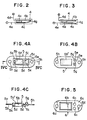
- the switch 4 which is of the normally closed type and forms a temperature sensor, may be for example, a self-holding, plastic type thermal protector manufactured by Matsushita Electric Industrial Co. Ltd., Japan. It includes a third stationary contact 4b connected by a lead 4d to a positive terminal and a bimetallic element 4c disposed in substantially parallel relationship with the stationary contact 4b and connected by another lead 4e to a negative terminal, as shown in Figure 2.
- a heater formed by a PTC element 4a is disposed between one end of the stationary contact 4b and the bimetallic element 4c.
- a movable contact 4g is secured to the free end of the bimetallic element 4c and normally held in electrically conductive engagement with the free end of the stationary contact 4b to close a circuit.
- the retainer member 5 by which the switch 4 is mounted on the plunger casing 1 is formed from an elastomeric material such as rubber and includes an outer peripheral flange section 5a of an arcuate cross-section suited for intimate and sealing engagement with the cylindrical outer surface of the plunger casing 1.
- a rectangular recess 5b is formed in the inner side of the retainer member 5 centrally thereof to receive and retain the switch 4 in the manner shown in Figure 1.
- the retainer member 5 is mounted on the plunger casing 1 with the recess 5b facing inwardly.
- a pair of protrusions 5d are formed integrally with the two opposed shorter sides of the rectangular recess 5b.
- a pair of generally cylindrical projections 5g on the outer side of the retainer member 5 in the flange section 5c thereof have through-holes 5e for the leads 4d and 4e of the switch 4.
- the recess 5b is laterally enlarged by notches or cutouts 5f formed in the longer sides of the recess 5b.
- a pair of screw holes 5h are formed in the longitudinal end portions of the flange 5a.
- the rectangular guide section 5c is slightly cut or recessed at 5i between one of the protrusions 5d and the lead holes 5e to provide space for the switch leads 4d and 4e extending from the recess 5b to the lead holes 5e.
- the cover member 6 by which the retainer member 5 is fixed to the plunger casing 1 is made of metal and serves to protect the retainer member 5. It is superposed upon the retainer member 5, as will be seen in Figure 1, and for this reason, includes an outer flange section 6a extending in face-to-face engagement with the flange 5a of the retainer member 5, a recess 6b snugly receiving the top or roof 5b' of the recess 5b of the retainer member 5, a first pair of through-holes 6c through which the projections 5g of the retainer member 5 extend outwardly, and a second pair of holes 6d formed in the flange section 6a in alignment with the screw holes 5h in the retainer member 5.
- the switch 4 For mounting the switch 4 on the plunger casing 1, the switch 4 is fitted into the recess 5b in the retainer member 5 with the two switch leads 4d and 4e extending through the groove 5i in the guide section 5c into and through the lead holes 5e.
- This assembly is mounted on the plunger casing 1 with the guide section 5c fitted into the opening 1 a.
- the cover member 6 is then placed on the retainer member 5 and fixed with the retainer member to the plunger casing 1 by means of screws 12, as shown in Figure 1.
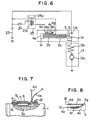
- the resiliency of the projections 5d urges the switch 4 into thermally conductive engagement with the outer peripheral surface of the outer holding coil 3b, as best seen in Figure 7.
- a space 5j is formed between the switch 4 and the inner surface of the roof of the recess 5b of the retainer member 5 to thermally isolate the outer surface of the switch 4 from the roof of the recess 5b of the retainer member 5. Since the cylindrical projections 5g are made of rubber, breakage of the switch leads 4d and 4e by repeated flexion is prevented.
- the retainer member 5 also serves to seal the opening 1a against water, dusts and so forth.
- the electrical circuit includes the first stationary contact 11 a which is electrically connected to the positive terminal of the battery 23, and the second stationary contact 11 b electrically connected through a field coil 13b to the armature 13a of the motor 13.
- the attracting coil 3a is electrically connected at one end to the second contact 11 b and to the holding coil 3b at the other end.
- a relay 25 includes normally open contacts 25a one of which is electrically connected to the positive terminal of the battery 23 and the other of which is electrically connected to the connection between the attracting and holding coils 3a and 3b.
- the lead 4d of the normally closed switch or temperature sensor 4 is electrically connected to one end of a coil 25b of the relay 25, the other end of the coil 25b being connected through a starter switch 24 to the positive terminal of the battery 23.
- the other switch lead 4e is grounded.
- the relay coil 25b is energised to close the normally open contacts 25a of the relay, so that DC current now passes through the relay 25 to the attracting coil 3a and the holding coil 3b.
- the coils 3a and 3b are energised to move the plunger 7 towards the first and second stationary contacts 11 a and 11 b.
- the plunger 7 pulls the upper end of the lever 21 engaged with the joint section 8 of the plunger 7, so that the lever 21 is rotated clockwise about the pivot pin 21 a to axially move the spline tube 15, the unidirectional clutch 16 and thus the pinion 17 towards the ring gear 18.
- a low-torque rotation of the motor 13 caused by the current passing through the attracting coil 3a cooperates with the axial thrust applied by the lever 21 to bring the pinion 17 into mesh with the ring gear 18.
- the axial thrust acts to move the plunger 7 until the movable contact 9 is brought into electrical contact with the first and second stationary contacts 11 a and 11 b to electrically connect them together.
- DC current flows to the motor 13 and the armature 13a rotates to drive the shaft 14.
- the rotation is transmitted by the spline tube 15 and the unidirectional clutch 16 to the pinion 17 which in turn drives the ring gear 18 to start the engine.
- the starter switch 24 opens to disconnect the relay coil 25b, so that the relay contacts 25a move to their normal open positions whereby the attracting and holding coils 3a and 3b are isolated.
- the return spring 10 moves the plunger 7 and the lever 21 to their initial positions and the pinion 17 and ring gear 18 are disengaged.
- the normally closed switch or temperature sensor 4 is designed to be opened when the temperature of the holding coil 3b reaches substantially 100 ° C.
- This temperature is chosen because the temperature sensor 4 must be kept closed for a time (typically, two minutes) sufficient to start the engine, but the sensor 4 should be opened in good time (less than about five minutes) to prevent damage to the unidirectional clutch 16 and the starter motor 13 by overrunning.
- the temperature of the holding coil 3b reaches about 100 ° C by continuous supply of current to the coil for five minutes.
- the PTC heater 4a is immediately heated due to the PTC characteristic thereof to maintain the temperature of the bimetallic element higher than the temperature (about 80°C) at which the bimetallic element 4c resumes its initial position. Therefore, the normally closed switch 4 is kept open even if the temperature of the deenergised holding coil 3b drops (by natural radiation) below the temperature at which the bimetallic element 4c resumes its initial position.
- the saturation current passing through the PTC heater 4a at this time is about 15mA which is much less than the current (zA) at which the relay 25 is operated.
- the PTC heater 4a of the normally closed switch 4 is deenergised to allow the bimetallic element 4c to cool by radiation of heat through the holding coil 3b, the retainer member 5 and the cover member 6.
- the bimetallic element returns to its normally closed position to move the movable contact 4g into contact with the stationary contact 4b, so that the starter is once again ready for use about 10 seconds after the starter switch 24 is turned off.
- the starter switch 24 is repeatedly turned on and off either when the pinion 17 is not well engaged with the ring gear 18 or when the movable contact 9 on the plunger 7 is not brought into a good electrically conductive contact with the first and second stationary contacts 11 a and 11 b, the attracting coil 3a is supplied with current. However, because of the high current flowing, the attracting coil 3a is heated rapidly and the normally closed switch 4, is heated by the heat produced in both the attracting and holding coils 3a and 3b. Acordingly, the electrical supply to the attracting and holding coils 3a and 3b is interrupted for the reasons
- the normally closed switch or temperature sensor 4 is disposed in contact with the outer periphery of the holding coil 3b.
- the holding coil 3b may alternatively be disposed radially inwardly of the attracting coil 3a and the temperature sensor 4 may be disposed in contact with or adjacent to the outer peripheral surface of the outer attracting coil 3a.
- the PTC heater 4a is replaced by a heating coil 4f wound around the bimetallic element 4c and electrically connected between the stationary contact 4b and the bimetallic element 4c.
- the coil 4f is energised to keep the bimetallic element 4c at a temperature higher than that at which the bimetallic element is returned to the closed position.
Landscapes
- Engineering & Computer Science (AREA)
- Power Engineering (AREA)
- Chemical & Material Sciences (AREA)
- Combustion & Propulsion (AREA)
- Mechanical Engineering (AREA)
- General Engineering & Computer Science (AREA)
- Thermally Actuated Switches (AREA)
- Connection Of Motors, Electrical Generators, Mechanical Devices, And The Like (AREA)
Claims (7)
Priority Applications (1)
| Application Number | Priority Date | Filing Date | Title |
|---|---|---|---|
| EP86303445A EP0244521B1 (de) | 1984-11-08 | 1986-05-07 | Anlasser für Verbrennungsmotor |
Applications Claiming Priority (2)
| Application Number | Priority Date | Filing Date | Title |
|---|---|---|---|
| JP59236317A JPS61116071A (ja) | 1984-11-08 | 1984-11-08 | スタ−タ |
| EP86303445A EP0244521B1 (de) | 1984-11-08 | 1986-05-07 | Anlasser für Verbrennungsmotor |
Publications (2)
| Publication Number | Publication Date |
|---|---|
| EP0244521A1 EP0244521A1 (de) | 1987-11-11 |
| EP0244521B1 true EP0244521B1 (de) | 1989-05-03 |
Family
ID=26104171
Family Applications (1)
| Application Number | Title | Priority Date | Filing Date |
|---|---|---|---|
| EP86303445A Expired EP0244521B1 (de) | 1984-11-08 | 1986-05-07 | Anlasser für Verbrennungsmotor |
Country Status (1)
| Country | Link |
|---|---|
| EP (1) | EP0244521B1 (de) |
Cited By (2)
| Publication number | Priority date | Publication date | Assignee | Title |
|---|---|---|---|---|
| DE102015207986A1 (de) * | 2015-04-30 | 2016-11-03 | Robert Bosch Gmbh | Startvorrichtung für eine Brennkraftmaschine |
| CN108603480A (zh) * | 2015-12-04 | 2018-09-28 | Seg汽车德国有限公司 | 电磁继电器、特别是用于起动装置的起动继电器 |
Families Citing this family (6)
| Publication number | Priority date | Publication date | Assignee | Title |
|---|---|---|---|---|
| DE3922492A1 (de) * | 1989-07-08 | 1991-01-17 | Bosch Gmbh Robert | Starterschutzschaltung |
| IT1249838B (it) * | 1991-10-15 | 1995-03-28 | Magneti Marelli Spa | Sistema di avviamento per un motore a combustione interna. |
| US7650865B2 (en) * | 2007-05-07 | 2010-01-26 | Honda Motor Company, Ltd. | Power equipment apparatus having engine with electric starter motor and manual starter mechanism |
| DE102010039044A1 (de) * | 2010-08-09 | 2012-02-09 | Robert Bosch Gmbh | Starter für eine Brennkraftmaschine eines Kraftfahrzeuges und Verfahren zum Herstellen eines solchen Starters |
| US9347415B2 (en) * | 2014-01-24 | 2016-05-24 | GM Global Technology Operations LLC | Driver output encoding systems and methods |
| DE102018109263A1 (de) | 2018-04-18 | 2019-10-24 | Seg Automotive Germany Gmbh | Starterrelais für eine Startvorrichtung |
Family Cites Families (2)
| Publication number | Priority date | Publication date | Assignee | Title |
|---|---|---|---|---|
| DE3002232A1 (de) * | 1980-01-23 | 1981-07-30 | Robert Bosch Gmbh, 7000 Stuttgart | Schalteinrichtung fuer elektrische andrehvorrichtungen fuer brennkraftmaschinen |
| DE8223614U1 (de) * | 1982-08-21 | 1985-05-09 | Limitor AG, 8022 Zürich | Bimetallschutzschalter |
-
1986
- 1986-05-07 EP EP86303445A patent/EP0244521B1/de not_active Expired
Non-Patent Citations (1)
| Title |
|---|
| Journal of Nippondenso Technical Disclosure, No.36-070, published July 15,1984. * |
Cited By (3)
| Publication number | Priority date | Publication date | Assignee | Title |
|---|---|---|---|---|
| DE102015207986A1 (de) * | 2015-04-30 | 2016-11-03 | Robert Bosch Gmbh | Startvorrichtung für eine Brennkraftmaschine |
| CN108603480A (zh) * | 2015-12-04 | 2018-09-28 | Seg汽车德国有限公司 | 电磁继电器、特别是用于起动装置的起动继电器 |
| CN108603480B (zh) * | 2015-12-04 | 2020-09-08 | Seg汽车德国有限公司 | 电磁继电器、特别是用于起动装置的起动继电器 |
Also Published As
| Publication number | Publication date |
|---|---|
| EP0244521A1 (de) | 1987-11-11 |
Similar Documents
| Publication | Publication Date | Title |
|---|---|---|
| US4674344A (en) | Engine starter | |
| US4389692A (en) | Overload-protected switching apparatus for electrical starter system for combustion engines | |
| KR930004816B1 (ko) | 냉장고 압축기 전동기 시스템 및 전동기 보호기 | |
| US4399423A (en) | Miniature electric circuit protector | |
| US6380831B1 (en) | Starter motor magnetic switch having auxiliary relay | |
| EP0771947B1 (de) | Anlasser mit Überhitzungsschutz | |
| US5053908A (en) | Psc motor start system | |
| EP1143475B1 (de) | Energieversorgungsanschluss-Struktur eines Anlasserschalters | |
| EP0244521A1 (de) | Anlasser für Verbrennungsmotor | |
| KR101450882B1 (ko) | 리셋 모터 보호기 | |
| GB1594334A (en) | Thermal protection for electric motors | |
| US4237508A (en) | Electrical control | |
| US5515229A (en) | Overcurrent protector with overheat prevention means | |
| US6356047B1 (en) | Starting device for electric motors, which includes a PTC resistor and a relay in series | |
| US4355458A (en) | Method of making an electrical control | |
| US5596307A (en) | Thermostat | |
| KR100709951B1 (ko) | 전동 모터 제어 장치 | |
| JPH02290142A (ja) | 車輌用スタータ保護装置 | |
| JPH0674778B2 (ja) | スタ−タ | |
| JPS63259160A (ja) | スタ−タ | |
| JP3775610B2 (ja) | スタータのマグネットスイッチ励磁端子 | |
| KR100642117B1 (ko) | 전동기용 시동 장치 | |
| KR20000038286A (ko) | 차량의 시동전동기 과열방지장치 | |
| CA1167715A (en) | Glow plug control device for diesel engines | |
| JPH0624114Y2 (ja) | 防水型ブレーカ |
Legal Events
| Date | Code | Title | Description |
|---|---|---|---|
| PUAI | Public reference made under article 153(3) epc to a published international application that has entered the european phase |
Free format text: ORIGINAL CODE: 0009012 |
|
| 17P | Request for examination filed |
Effective date: 19870406 |
|
| AK | Designated contracting states |
Kind code of ref document: A1 Designated state(s): FR GB IT |
|
| 17Q | First examination report despatched |
Effective date: 19880212 |
|
| GRAA | (expected) grant |
Free format text: ORIGINAL CODE: 0009210 |
|
| AK | Designated contracting states |
Kind code of ref document: B1 Designated state(s): FR GB IT |
|
| ET | Fr: translation filed | ||
| ITF | It: translation for a ep patent filed | ||
| REG | Reference to a national code |
Ref country code: GB Ref legal event code: 746 |
|
| ITPR | It: changes in ownership of a european patent |
Owner name: OFFERTA DI LICENZA AL PUBBLICO |
|
| REG | Reference to a national code |
Ref country code: FR Ref legal event code: DL |
|
| PLBI | Opposition filed |
Free format text: ORIGINAL CODE: 0009260 |
|
| 26 | Opposition filed |
Opponent name: ROBERT BOSCH GMBH Effective date: 19900130 |
|
| ITTA | It: last paid annual fee | ||
| PLBN | Opposition rejected |
Free format text: ORIGINAL CODE: 0009273 |
|
| STAA | Information on the status of an ep patent application or granted ep patent |
Free format text: STATUS: OPPOSITION REJECTED |
|
| 27O | Opposition rejected |
Effective date: 19910514 |
|
| REG | Reference to a national code |
Ref country code: GB Ref legal event code: IF02 |
|
| PGFP | Annual fee paid to national office [announced via postgrant information from national office to epo] |
Ref country code: GB Payment date: 20040505 Year of fee payment: 19 |
|
| PGFP | Annual fee paid to national office [announced via postgrant information from national office to epo] |
Ref country code: FR Payment date: 20040510 Year of fee payment: 19 |
|
| PG25 | Lapsed in a contracting state [announced via postgrant information from national office to epo] |
Ref country code: IT Free format text: LAPSE BECAUSE OF NON-PAYMENT OF DUE FEES;WARNING: LAPSES OF ITALIAN PATENTS WITH EFFECTIVE DATE BEFORE 2007 MAY HAVE OCCURRED AT ANY TIME BEFORE 2007. THE CORRECT EFFECTIVE DATE MAY BE DIFFERENT FROM THE ONE RECORDED. Effective date: 20050507 Ref country code: GB Free format text: LAPSE BECAUSE OF NON-PAYMENT OF DUE FEES Effective date: 20050507 |
|
| GBPC | Gb: european patent ceased through non-payment of renewal fee |
Effective date: 20050507 |
|
| PG25 | Lapsed in a contracting state [announced via postgrant information from national office to epo] |
Ref country code: FR Free format text: LAPSE BECAUSE OF NON-PAYMENT OF DUE FEES Effective date: 20060131 |
|
| REG | Reference to a national code |
Ref country code: FR Ref legal event code: ST Effective date: 20060131 |