EP0244035A1 - Method and device for producing marking lines on a mat of mineral fibres containing a binding agent - Google Patents
Method and device for producing marking lines on a mat of mineral fibres containing a binding agent Download PDFInfo
- Publication number
- EP0244035A1 EP0244035A1 EP87200792A EP87200792A EP0244035A1 EP 0244035 A1 EP0244035 A1 EP 0244035A1 EP 87200792 A EP87200792 A EP 87200792A EP 87200792 A EP87200792 A EP 87200792A EP 0244035 A1 EP0244035 A1 EP 0244035A1
- Authority
- EP
- European Patent Office
- Prior art keywords
- roller
- mineral fiber
- fiber web
- heating
- marking
- Prior art date
- Legal status (The legal status is an assumption and is not a legal conclusion. Google has not performed a legal analysis and makes no representation as to the accuracy of the status listed.)
- Granted
Links
- 239000011230 binding agent Substances 0.000 title claims abstract description 15
- 238000000034 method Methods 0.000 title claims description 16
- 229910052500 inorganic mineral Inorganic materials 0.000 title abstract 7
- 239000011707 mineral Substances 0.000 title abstract 7
- 238000010438 heat treatment Methods 0.000 claims abstract description 87
- 230000002093 peripheral effect Effects 0.000 claims abstract description 12
- 238000000354 decomposition reaction Methods 0.000 claims abstract description 10
- 230000000694 effects Effects 0.000 claims abstract description 5
- 239000002557 mineral fiber Substances 0.000 claims description 84
- 239000000463 material Substances 0.000 claims description 15
- 238000004519 manufacturing process Methods 0.000 claims description 9
- 239000011810 insulating material Substances 0.000 claims description 2
- 239000000835 fiber Substances 0.000 abstract description 9
- 239000002184 metal Substances 0.000 abstract description 2
- 238000005096 rolling process Methods 0.000 abstract 1
- 230000035515 penetration Effects 0.000 description 9
- 238000012546 transfer Methods 0.000 description 7
- 230000015572 biosynthetic process Effects 0.000 description 5
- 238000013461 design Methods 0.000 description 4
- 238000003860 storage Methods 0.000 description 3
- KXGFMDJXCMQABM-UHFFFAOYSA-N 2-methoxy-6-methylphenol Chemical group [CH]OC1=CC=CC([CH])=C1O KXGFMDJXCMQABM-UHFFFAOYSA-N 0.000 description 2
- 239000010425 asbestos Substances 0.000 description 2
- 230000004323 axial length Effects 0.000 description 2
- 238000010276 construction Methods 0.000 description 2
- 238000001816 cooling Methods 0.000 description 2
- 238000005265 energy consumption Methods 0.000 description 2
- 238000005516 engineering process Methods 0.000 description 2
- 238000007373 indentation Methods 0.000 description 2
- 239000005011 phenolic resin Substances 0.000 description 2
- 229920001568 phenolic resin Polymers 0.000 description 2
- 229910052895 riebeckite Inorganic materials 0.000 description 2
- 230000001360 synchronised effect Effects 0.000 description 2
- 230000003313 weakening effect Effects 0.000 description 2
- 230000006978 adaptation Effects 0.000 description 1
- 230000015556 catabolic process Effects 0.000 description 1
- 239000002131 composite material Substances 0.000 description 1
- 239000004020 conductor Substances 0.000 description 1
- 230000001276 controlling effect Effects 0.000 description 1
- 230000001186 cumulative effect Effects 0.000 description 1
- 230000006735 deficit Effects 0.000 description 1
- 238000006731 degradation reaction Methods 0.000 description 1
- 238000011982 device technology Methods 0.000 description 1
- 238000002845 discoloration Methods 0.000 description 1
- 239000002706 dry binder Substances 0.000 description 1
- 230000002349 favourable effect Effects 0.000 description 1
- 238000007654 immersion Methods 0.000 description 1
- 230000006698 induction Effects 0.000 description 1
- 239000012774 insulation material Substances 0.000 description 1
- 238000002372 labelling Methods 0.000 description 1
- 238000003475 lamination Methods 0.000 description 1
- 238000012423 maintenance Methods 0.000 description 1
- 230000000149 penetrating effect Effects 0.000 description 1
- 238000003825 pressing Methods 0.000 description 1
- 230000005855 radiation Effects 0.000 description 1
- 230000001105 regulatory effect Effects 0.000 description 1
- 239000002344 surface layer Substances 0.000 description 1
- 238000003466 welding Methods 0.000 description 1
- 238000004804 winding Methods 0.000 description 1
Images

Classifications
-
- E—FIXED CONSTRUCTIONS
- E04—BUILDING
- E04D—ROOF COVERINGS; SKY-LIGHTS; GUTTERS; ROOF-WORKING TOOLS
- E04D13/00—Special arrangements or devices in connection with roof coverings; Protection against birds; Roof drainage; Sky-lights
- E04D13/16—Insulating devices or arrangements in so far as the roof covering is concerned, e.g. characterised by the material or composition of the roof insulating material or its integration in the roof structure
- E04D13/1606—Insulation of the roof covering characterised by its integration in the roof structure
- E04D13/1612—Insulation of the roof covering characterised by its integration in the roof structure the roof structure comprising a supporting framework of roof purlins or rafters
- E04D13/1625—Insulation of the roof covering characterised by its integration in the roof structure the roof structure comprising a supporting framework of roof purlins or rafters with means for supporting the insulating material between the purlins or rafters
-
- B—PERFORMING OPERATIONS; TRANSPORTING
- B44—DECORATIVE ARTS
- B44B—MACHINES, APPARATUS OR TOOLS FOR ARTISTIC WORK, e.g. FOR SCULPTURING, GUILLOCHING, CARVING, BRANDING, INLAYING
- B44B5/00—Machines or apparatus for embossing decorations or marks, e.g. embossing coins
- B44B5/02—Dies; Accessories
- B44B5/028—Heated dies
-
- B—PERFORMING OPERATIONS; TRANSPORTING
- B44—DECORATIVE ARTS
- B44B—MACHINES, APPARATUS OR TOOLS FOR ARTISTIC WORK, e.g. FOR SCULPTURING, GUILLOCHING, CARVING, BRANDING, INLAYING
- B44B7/00—Machines, apparatus or hand tools for branding, e.g. using radiant energy such as laser beams
-
- E—FIXED CONSTRUCTIONS
- E04—BUILDING
- E04B—GENERAL BUILDING CONSTRUCTIONS; WALLS, e.g. PARTITIONS; ROOFS; FLOORS; CEILINGS; INSULATION OR OTHER PROTECTION OF BUILDINGS
- E04B1/00—Constructions in general; Structures which are not restricted either to walls, e.g. partitions, or floors or ceilings or roofs
- E04B1/62—Insulation or other protection; Elements or use of specified material therefor
- E04B1/74—Heat, sound or noise insulation, absorption, or reflection; Other building methods affording favourable thermal or acoustical conditions, e.g. accumulating of heat within walls
- E04B1/76—Heat, sound or noise insulation, absorption, or reflection; Other building methods affording favourable thermal or acoustical conditions, e.g. accumulating of heat within walls specifically with respect to heat only
- E04B1/7654—Heat, sound or noise insulation, absorption, or reflection; Other building methods affording favourable thermal or acoustical conditions, e.g. accumulating of heat within walls specifically with respect to heat only comprising an insulating layer, disposed between two longitudinal supporting elements, e.g. to insulate ceilings
- E04B1/7658—Heat, sound or noise insulation, absorption, or reflection; Other building methods affording favourable thermal or acoustical conditions, e.g. accumulating of heat within walls specifically with respect to heat only comprising an insulating layer, disposed between two longitudinal supporting elements, e.g. to insulate ceilings comprising fiber insulation, e.g. as panels or loose filled fibres
- E04B1/7662—Heat, sound or noise insulation, absorption, or reflection; Other building methods affording favourable thermal or acoustical conditions, e.g. accumulating of heat within walls specifically with respect to heat only comprising an insulating layer, disposed between two longitudinal supporting elements, e.g. to insulate ceilings comprising fiber insulation, e.g. as panels or loose filled fibres comprising fiber blankets or batts
-
- E—FIXED CONSTRUCTIONS
- E04—BUILDING
- E04D—ROOF COVERINGS; SKY-LIGHTS; GUTTERS; ROOF-WORKING TOOLS
- E04D13/00—Special arrangements or devices in connection with roof coverings; Protection against birds; Roof drainage; Sky-lights
- E04D13/16—Insulating devices or arrangements in so far as the roof covering is concerned, e.g. characterised by the material or composition of the roof insulating material or its integration in the roof structure
-
- E—FIXED CONSTRUCTIONS
- E04—BUILDING
- E04B—GENERAL BUILDING CONSTRUCTIONS; WALLS, e.g. PARTITIONS; ROOFS; FLOORS; CEILINGS; INSULATION OR OTHER PROTECTION OF BUILDINGS
- E04B1/00—Constructions in general; Structures which are not restricted either to walls, e.g. partitions, or floors or ceilings or roofs
- E04B1/62—Insulation or other protection; Elements or use of specified material therefor
- E04B1/74—Heat, sound or noise insulation, absorption, or reflection; Other building methods affording favourable thermal or acoustical conditions, e.g. accumulating of heat within walls
- E04B2001/741—Insulation elements with markings, e.g. identification or cutting template
Definitions
- the invention relates to a method for applying marking lines to a mineral fiber web containing binder, according to the preamble of claim 1.
- the marking lines to be applied there run in the longitudinal direction of the mineral fiber web, that is to say in its transport or production direction.
- a penetration marking is generated in such a way that a sharply focused flame or a sharply focused hot air jet 0 with a temperature of, for example, 600 ° C. is directed onto the surface of the mineral fiber web, which in its core area the binder on the surface of the mineral fiber web to its decomposition temperature warmed and so discolored.
- a marking line running parallel to the edge in the longitudinal direction of the web it is therefore only necessary to arrange a corresponding hot air nozzle or flame lance above the running mineral fiber web.
- a roller as a heating device.
- this heating device in the form of a roller is not used to apply marking lines, but rather deep into the material of the M i. to generate penetrating tack points by locally softening the mineral fibers and thus welding them together.
- the circumferential surface of the roller has rows of openings through which hot gas at a high temperature, as a rule up to 1000 ° C., emerges in a lance-shaped manner.
- the peripheral surface of the roller lies on the surface of the mineral fiber web and the roller rotates at a speed which corresponds to the transport speed of the mineral fiber web.
- a hot gas outlet through a row of holes is only permitted if it lies in the region of the lower vertex of the roller, so that the hot gas lances into the mineral fiber web from each opening and forms tack points.
- the depth of penetration can be further promoted by the negative pressure generated on the opposite side of the mineral fiber web.
- Such a device is not used to apply marking lines and is also not suitable for generating marking lines which practically do not influence the behavior of the mineral fiber material at the marking point.
- the large penetration depth desired in the known case can be reduced by throttling the hot gas supply, but it is considerable in any case if by a local hot gas flow so much energy is to be introduced during the contact time that there is a rich discoloration.
- the lateral limitation of the area of action of the hot gas is difficult to control, especially since the action takes place in the course of the rotation of the roller and thus with a changing direction.
- lateral flow portions play a role, which in the edge region of the marking still partially decompose the binder and thus lead to an unsharp boundary of the marking.
- the invention has for its object to provide a method and an apparatus which enable the application of marking lines running transversely to the side edges on a surface of a mineral fiber web in the simplest and most reliable manner possible with a shallow depth of penetration of the decomposition phenomena allow the application of clearly delimited marking lines at exact and constant distances from each other.
- the roller can be rotated at a peripheral speed which deviates slightly from the transport speed of the mineral fiber web, in order to compensate for such small inaccuracies due to the contact conditions between the roller and the mineral fiber web.
- the roller according to claim 2 is pressed into the surface of the mineral fiber web to form a trough.
- a V produces ER improvement of the conductive heat transfer from the heating zone to the mineral fibers.
- the trough formation associated with the indentation results in an extension of the contact time between the heating zone and mineral fibers and thus also an improvement in the heat transfer.
- the heat transfer can thus be adapted to the need for the formation of a clean marking without excessive heat input into the mineral fiber web: at a very slow transport speed, the roller is only slightly pressed and thus the contact pressure and the contact path are reduced, so that the desired heat input takes place with regard to the relatively long contact time available at low transport speed, while at high transport speed the heat transfer in the short time available is increased accordingly by increasing the contact pressure and lengthening the contact path.
- the heat input into the mineral fiber web can also be completely or additionally influenced by controlling the temperature of the heating zones.
- the thermal load on the mineral fiber web at the point of contact with the heating zones on the other hand a relatively narrow optimal temperature range, which should be maintained as far as possible.
- the different setting of the penetration depth of the roller into the surface of the mineral fiber web enables a corresponding adjustment of the heat input without the temperature of the heating zones having to leave the optimal operating range.
- the measure of claim 4 also enables a considerable simplification of the structural design of a device required for carrying out the method, since a rotary drive can be omitted for operation and at most a simple rotary drive is required for preheating the roller in order to ensure uniform heating to ensure the heating zones distributed over the circumference of the roller.
- the measure of claim 5 results in broken, so to speak broken lines. These generally serve their purpose, and make it possible to work with individual, shorter, spaced-apart heating zones which, with regard to their smaller linear expansion, avoid problems with addition of the thermal expansion in the longitudinal direction. In addition, the energy consumption is reduced and any impairment of the material consistency by tensile or compressive loading of the fibers in the winding is avoided by the fact that sectionally completely unaffected material is present.
- a device which is particularly suitable for carrying out the method according to the invention is characterized in detail by the characterizing features of claim 6.
- Heating rods form a particularly favorable constructive possibility for forming the heating zones required according to the method.
- Straight heating rods can be used to form straight line markings; however, other markings such as rasters, monograms or the like can also be generated if the heating rods are shaped in accordance with the respectively desired marking contour.
- the measures of claim 7 ensure that energy losses due to heat radiation or heat conduction from the heating rods are minimized, while at the same time a particularly bordering the heating rods through the good thermal insulation material of the holder results in a sharp delimitation of the heating zones and ensures clean edges of the marking lines.
- the heating rods protrude a small amount from the circumferential surface of the roller, the air surrounding the heating rods ensures cooling of the mineral fiber mat adjacent to the marking strips rials during the marking and thus promotes a clean formation of the edges of the marking lines. Furthermore, especially when the roller is pressed deeper into the mineral fiber web, the entrainment effect of the mineral fiber material on the roller increases, since protruding edges of the heating rods favor the entrainment effect.
- heating elements can be heated by embedded electrical tubular heating elements, there is a constructive freedom of design for the heating elements.
- a commercially available tubular heating element can be used, which results in low procurement costs and high operational reliability, without the outside ' contour of which would restrict the free movement of the heating elements.
- any type of suitable heating device including a contactless one, e.g. B. induction heating can be used as long as it is ensured that the desired heating can take place locally in the heating zones.
- a particularly advantageous design results from the use of an inner support body for the roller in the form of a cylindrical polygon.
- Each straight surface of the polygon can be a support for the holder and the internals of a heating element in a structurally simple manner.
- the drive speed of the roller can be synchronized with that of the conveyor or production belt in a simple manner by using a DC motor for driving the roller.
- an electric motor with a freewheel which is expediently designed as a three-phase motor, is preferably provided in the heating phase for the continuous slow rotation of the roller at an uncritical speed moderate heating of the heating elements, and its free running allows the motor to be overtaken as soon as the roller lies on the mineral fiber web and is driven by it at increased speed. With each interruption in operation, the electric motor then continues to rotate the lifted roller in order to ensure that the heating elements are always heated uniformly.
- the bearing frame of the roller is held in a positively adjustable position in its height by means of an actuator.
- the pressing conditions of the roller on the mineral fiber web can be fine-tuned at any time in such a way that the markings are optimally formed as a function of the current transport speed of the mineral fiber web.
- the actuator expediently has at least one threaded spindle, which can be driven, for example, by an electric stepper motor and thus ensures problem-free fine adjustment and its maintenance by remote control.
- the threaded spindles preferably engage a holding frame for the lifting and lowering storage frame, which is also designed to be raised and lowered. According to claim 14, this holding frame is connected to the storage frame via a pressure medium drive and the latter can be moved between an operating position and a rest position by the pressure medium drive.
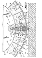
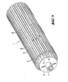
- Fig.-1 denotes a roller, as shown in Fig. 2 enlarged with details and in Fig. 3 schematically simplified perspective.
- Fig. 1 only the left end of the roller 1 is illustrated in the example, it being understood that there is a corresponding bearing of the roller at the opposite end.
- 2 denotes a shaft, which is connected to the roller 1 and serves to support it.
- the roller 1 is supported on the shaft 2 on a bearing frame 3 by means of bearings 4 on both sides. Outside the bearing 4, the shaft 2 projects into an electrical connection box 5 in which, in a known manner, a schematically illustrated slip ring 6 supplies the rotating parts of the roller with a power supply 1 is done.
- the roller 1 can be rotated in the bearing 4 via the shaft 2.
- an electric motor 7 is provided, which is mounted on the bearing frame 3 and drives a drive gear 9, which is connected to the shaft 2 in a rotationally fixed manner, with an output pinion 8 via a toothed belt or the like. In this way, the roller 1 can be rotated in the bearings 4.
- the storage rack 3 is guided up and down on columns 10 of a stationary portal, generally designated 11.
- a holding frame 12 with a cross member 13 is guided up and down on the columns 10.
- the bearing frame 3 is held on the holding frame 12 via pressure medium drives 14 in the form of, for example, pneumatic cylinders 15 which are mounted on the crossmember 13 and whose piston rods 16 act on the bearing frame 3 at 17.
- pressure medium drives 14 in the form of, for example, pneumatic cylinders 15 which are mounted on the crossmember 13 and whose piston rods 16 act on the bearing frame 3 at 17.
- the holding frame 12 is in turn connected via actuators 18 to a cross member 19 of the fixed portal 11.
- the actuators 18, for example in the form of threaded spindles 20, are actuated by an electric motor 21, for example in the form of a stepping motor and gear 22.
- the height of the crossmember 13 and the holding frame 12 can be finely adjusted in a desired position via the actuating drives 18.
- the piston rod 16 of the pressure medium drives 14 is extended, this results in a corresponding specific height position of the roller 1.
- the roller 1 can be lowered into this predetermined operating position or raised to a rest position. without changing the position of the holding frame 12 and thus canceling the set fine adjustment.
- the lower region of the roller 1 is shown in an end view and partly in section in the operating position.
- the roller 1 has a support body 23 in the form of a polygon, in the example in the form of a 20-corner, on the flat lateral surfaces 24 of which holders 25 for heating rods 26 are held by screws 27.
- the heating rods 26 have a bearing body 28 arranged in the interior of the holder 25 and also marking ribs 30 protruding from the peripheral surface of the roller 1, designated 29.
- the heating rods 26 consist of a suitable, good heat-conducting metal and have in the area of their bearing body 28 a round recess 31 in the example for receiving conventional tubular heaters 32 - similar to heating coils from immersion heaters.
- the heating rods 26 are divided in a plane 33 radial to the axis of the roller 1, the parts 26a and 26b of the heating rods 26 thus formed being connected to one another by suitable countersunk screws 34 and 35.
- the tubular heaters 32 After the tubular heaters 32 have been installed in the recess 31 of the two open parts 26a and 26b of the heating rods 26, the heating rods 26 are preassembled by inserting the screws 34 and 35 and inserted into the holder 25. Then the holders 25 are provided on their circumferential outer side with cover plates 36 which overlap shoulders 37 of the bearing body 28 of each heating element 26 and thus hold it securely in the holder 25.
- the holder 25 and the cover plates 36 consist of a suitable, poorly heat-conducting material such as a fibrous or fibrous press material based on asbestos or asbestos substitute in order to avoid heat losses of the heating rods 26 and the areas of the peripheral surface 29 on both sides of the marking ribs 30 to protect against heating and heat transfer to the mineral fiber material of the mineral fiber web designated 38. In this way, all sides of the heating rods 26 lying within the peripheral surface 29 of the roller 1 are surrounded by heat-insulating material.
- Each heating rod 26 has a recess 39 for receiving an earth cable. At least one of the heating rods 26 also has a recess 40 in the vicinity of its marking rib 30 for receiving a thermal sensor.
- the temperature control using the thermal sensor and the power supply to the tubular heater 32 is carried out via the slip rings 6 (see FIG. 1).
- temperature control using thermal sensors can also be dispensed with, and instead only the power supply to the tubular heating elements 32 can be regulated. In stationary operation, a certain temperature then results which is suitable for producing the markings, the optimum formation of the markings being able to be set by the degree of impression of the roller 1 in the mineral fiber web 38.
- the marking ribs 30 of the heating rods 26 and possibly the heating rods themselves extend only over part of the axial length of the roller 1, so that a plurality of marking ribs 30 form an interrupted line along a surface line of the roller 1 and at an axial distance are arranged from each other. If the length of the heating rods 26 is limited to the axial extent of the marking ribs 30, this results in a plurality of individual, shorter heating rods with easily controllable thermal expansions.
- the heating rods 26 can then be connected to one another through lines or a correspondingly circumferentially insulated piece of tubular heater 32 which connects the heating rods 26 approximately in an arc shape.
- the heating rods 26 pass over the entire axial length of the roller 1 and only between the protruding sections of the heating rods 26 designated as marking ribs 30, the gaps required to interrupt the marking are present, a very robust and stable construction results, in which the Tubular heating elements 32 are embedded in the heating rods 26 over their entire length.
- the mineral fiber web 38 is preferably of a type such as is explained in the context of the priority-establishing German patent application P 36 12 858.9-25.
- it may be an unclad mineral fiber web 38 with a width of 1200 mm, a nominal thickness of 100 mm and a length of 6 m.
- the bulk density may be between 10 and 30 kg / m, in particular between 14 3 and 25 kg / m, and in the specific example case 18 kg / m.
- Particularly suitable as a binder is phenolic resin in a proportion of 6 to 7% by weight of the dry binder in the product, the binder content of phenolic resin being 6.6% by weight (dry) in the example.
- the roller 1 In operation, with the piston rods 16 retracted, the roller 1 is set in rotation by the electric motor 7 above the surface of the mineral fiber web 38 denoted by 41, the heating rods 26 being preheated to a desired temperature, optionally monitored by the thermal sensors, by supplying current to the tubular heating elements 32.
- the rotation in the preheating phase ensures uniform heat losses of the individual heating rods 26 and marking ribs 30 and thus their uniform heating without individual temperature control on each individual heating rod 26.
- the piston rods 16 are extended and the roller 1 is lowered onto the surface 41 of the mineral fiber web 38, by means of the electric motor 21 and the actuators 18 can be used to fine-tune the height of the roller 1 over the mineral fiber web 38.
- the setting is appropriately chosen so that the marking ribs 30 on the circumference of the roller 1 press the surface 41 of the mineral fiber web 38 to form a trough 42.
- the surface 41 of the mineral fiber web 38 is typically uncovered, that is to say is formed by the mineral fiber tangle itself; however, the surface 41 can also have a lamination, for example in the form of a fleece based on mineral fibers or of other fibers.
- the marking rib 30 has a temperature of typically of the order of 400 ° C. and produces a zone of the decomposition of the binder in the mineral fiber web 38, indicated by dash-dotted lines, which is discolored.
- marking lines are formed on the surface 41 of the mineral fiber web 38, which extend transversely to the side edges of the mineral fiber web 41.
- the roller 1 can be continuously driven synchronously with the transport speed of the mineral fiber web 38.
- a DC motor is then expediently used as the electric motor 7.
- the electric motor 7 uses a three-phase motor, which is connected via a freewheel 44 to the output pinion 8, such that when the roller 1 is driven from the mineral fiber web 38, the rotational speed of the roller 1 can overtake that of the electric motor 7.
- the drive by the electric motor 7 is used exclusively to maintain a minimum rotational speed which is not critical in terms of the rotational speed in the raised rest position when the drive is removed from the mineral fiber web 38, in order to ensure uniform heating of the heating rods 26.
- the heat transfer conditions between the marking ribs 30 and the surface 41 of the mineral fiber web 38 can be adjusted in the manner described to form optimal marking lines. With a given transport speed and consistency of the mineral fiber web 38, however, such a fine adjustment can also be dispensed with, since it is then possible to work with a fixed presetting of the impression behavior of the roller 1 into the surface 41 of the mineral fiber web 38. In this way, the construction for mounting the roller 1 can be significantly simplified.
- the pressure medium drives 14 can be depressurized in the operating position, so that the roller simply with its own weight on the Mineral fiber web 38 rests.
- excessive penetration can be avoided by the fact that the marking ribs 30 do not protrude from the undisturbed circumferential surface 29 of the roller 1 by a few millimeters, in the example, approximately 8 mm, but rather lie within the undisturbed circumferential surface 29, so that these - for example in the form of cover plates 36 - helping to carry the weight and thus avoiding excessive local penetration.
- the illustrated embodiment with marking ribs 30 protruding from the peripheral surface 29 is particularly well suited for driving the roller 1 from the mineral fiber web 38.
Abstract
Description
Die Erfindung-betrifft ein.Verfahren zum Aufbringen von Markierungslinien auf eine bindemittelhaltige Mineralfaserbahn, nach dem Oberbegriff des Anspruchs 1.The invention relates to a method for applying marking lines to a mineral fiber web containing binder, according to the preamble of
Ein solches Verfahren ist aus der DE-OS 32 29 601 bekannt. Die dort aufzubringenden Markierungslinien verlaufen in Längsrichtung der Mineralfaserbahn, also in deren Transport- oder Produktionsrichtung. Zur Vermeidung eines Farbstoffauftrages mit relativ aufwendiger Aufbringtechnik, Materialverbrauch und möglicherweise Beeinflussung des Brandverhaltens wird eine Einbrandmarkierung in der Weise erzeugt, daß eine scharf gebündelte Flamme oder ein scharf gebündelter Heißluftstrahl 0 mit einer Temperatur von beispielsweise 600 C auf die Oberfläche der Mineralfaserbahn gerichtet wird, der in seinem Kernbereich das Bindemittel an der Oberfläche der Mineralfaserbahn auf seine Zersetzungstemperatur erwärmt und so verfärbt. Zur Erzeugung einer in Längsrichtung der Bahn randparallel durchlaufenden Markierungslinie ist somit lediglich die Anordnung einer entsprechenden Heißluftdüse oder Flammenlanze über der laufenden Mineralfaserbahn erforderlich.Such a method is known from DE-OS 32 29 601. The marking lines to be applied there run in the longitudinal direction of the mineral fiber web, that is to say in its transport or production direction. In order to avoid the application of a dye with a relatively complex application technique, material consumption and possibly influencing the fire behavior, a penetration marking is generated in such a way that a sharply focused flame or a sharply focused hot air jet 0 with a temperature of, for example, 600 ° C. is directed onto the surface of the mineral fiber web, which in its core area the binder on the surface of the mineral fiber web to its decomposition temperature warmed and so discolored. To generate a marking line running parallel to the edge in the longitudinal direction of the web, it is therefore only necessary to arrange a corresponding hot air nozzle or flame lance above the running mineral fiber web.
Ein solches Vorgehen ist jedoch auf die Anbringung randparalleler Markierungslinien beschränkt; zur Erzeugung von senkrecht zu den seitlichen Rändern verlaufenden Markierungslinien könnte die Heißluftdüse oder dergleichen nicht mehr stationär angeordnet werden, sondern müßte quer über die Mineralfaserbahn traversieren und dabei mit der Mineralfaserbahn mitbewegt werden, was jedoch zur Erzielung definitiver und gleichbleibender Markierungsabstände erheblichen anlagen- und insbesondere steuerungstechnischen Aufwand erfordern würde. Weiterhin erzeugt eine derartige Flamme oder ein solcher Heißluftstrahl nicht nur eine auf den unmittelbaren Oberflächenbereich begrenzte Zersetzung des Bindemittels, sondern zeigt zwangsläufig auch eine nicht unerhebliche Tiefenwirkung. Dadurch entsteht an der Markierungslinie eine mehr oder weniger weit in die Mineralfaserbahn eindringende Zone, in der kein Bindemittel wirksam ist. Dies ist im bekannten Fall unschädlich, da diese Zone in Längsrichtung der Bahn verläuft und somit keinen quer zur Richtung der Markierungslinie wirkenden Kräften ausgesetzt ist. Da derartige Mineralfaserbahnen in aller Regel zu einem Wickel aufgerollt und in Rollenform gelagert und transportiert werden, treten jedoch an quer zur Längserstreckung der Mineralfaserbahn liegenden bindemittelfreien Zonen Kräfte auf: Liegt die Markierungsseite im Wickel außen, so tendiert das Material an der Markierungslinie zur Klaffung, liegt sie innen, tendiert das Material zur Kompression. Hierdurch kann sich durch teilweise Auflösung des Faserverbundes im Bereich der Markierungslinie bei Zugkräften bzw. durch im Bereich der Markierungslinie erhöht auftretende Walkarbeit bei einwirkenden Druckkräften eine Schwächung des Produktes ergeben. Eine solche Schwächung ist insbesondere dann unerwünscht, wenn das Material anschließend an das Öffnen der Rolle mit homogener, plattenähnlicher Konsistenz vorliegen soll, wie dies gemäß der parallelen deutschen Patentanmeldung 36 12 858.9-25 der Fall ist.However, such a procedure is limited to the application of marking lines parallel to the edge; To generate marking lines running perpendicular to the lateral edges, the hot air nozzle or the like could no longer be arranged in a stationary manner, but would have to traverse across the mineral fiber web and thereby be moved along with the mineral fiber web, which, however, requires considerable plant and, in particular, control technology to achieve definitive and constant marking distances Would require effort. Furthermore, such a flame or such a hot air jet not only produces a decomposition of the binder that is limited to the immediate surface area, but inevitably also shows a not inconsiderable depth effect. This creates a zone on the marking line that penetrates more or less deeply into the mineral fiber web and in which no binding agent is effective. This is harmless in the known case, since this zone runs in the longitudinal direction of the web and is therefore not exposed to any forces acting transversely to the direction of the marking line. Since mineral fiber webs of this type are generally rolled up into a roll and stored and transported in roll form, forces occur, however, in binder-free zones lying transversely to the longitudinal extension of the mineral fiber web: if the marking side lies in the roll on the outside, the material tends to gap at the marking line inside, the material tends to compress. As a result, partial disintegration of the fiber composite in the area of the marking line in the case of tensile forces or increased flexing work occurring in the area of the marking line pressure forces result in a weakening of the product. Such weakening is particularly undesirable if the material is to be present after the opening of the roll with a homogeneous, plate-like consistency, as is the case according to the parallel
Aus der DE-OS 34 46 406 ist es bekannt, als Heizeinrichtung eine Walze zu verwenden. Diese Heizeinrichtung in Form einer Walze dient jedoch nicht dazu, Markierungslinien aufzubringen, sondern tief in das Material der Mi-. neralfaserbahn eindringende Heftpunkte dadurch zu erzeugen, daß die Mineralfasern lokal erweicht und so miteinander verschweißt werden-. Hierzu weist die Umfangsoberfläche der Walze Reihen von Öffnungen auf, durch die o Heißgas mit hoher Temperatur in der Regel bis zu 1000 C lanzenförmig austritt. Die Umfangsoberfläche der Walze liegt auf der Oberfläche der Mineralfaserbahn auf, und die Walze dreht sich mit einer solchen Geschwindigkeit, die der Transportgeschwindigkeit der Mineralfaserbahn entspricht. Ein Heißgasaustritt durch eine Lochreihe wird nur dann zugelassen, wenn diese im Bereich des unteren Scheitelpunkts der Walze liegt, so daß das Heißgas aus jeder Öffnung lanzenartig in die Mineralfaserbahn hineinsticht und Heftpunkte bildet. Die Eindringtiefe kann dabei durch an der gegenüberliegenden Seite der Mineralfaserbahn erzeugten Unterdruck weiter gefördert werden.From DE-OS 34 46 406 it is known to use a roller as a heating device. However, this heating device in the form of a roller is not used to apply marking lines, but rather deep into the material of the M i. to generate penetrating tack points by locally softening the mineral fibers and thus welding them together. For this purpose, the circumferential surface of the roller has rows of openings through which hot gas at a high temperature, as a rule up to 1000 ° C., emerges in a lance-shaped manner. The peripheral surface of the roller lies on the surface of the mineral fiber web and the roller rotates at a speed which corresponds to the transport speed of the mineral fiber web. A hot gas outlet through a row of holes is only permitted if it lies in the region of the lower vertex of the roller, so that the hot gas lances into the mineral fiber web from each opening and forms tack points. The depth of penetration can be further promoted by the negative pressure generated on the opposite side of the mineral fiber web.
Eine solche Vorrichtung dient nicht zum Anbringen von Markierungslinien, und ist auch nicht zur Erzeugung von Markierungslinien geeignet, welche das Verhalten des Mineralfasermaterials an der Markierungsstelle praktisch nicht beeinflussen. Die im bekannten Fall gewünschte große Eindringtiefe kann zwar durch Drosselung der Heißgaszufuhr vermindert werden, sie ist jedoch in jedem Falle erheblich, wenn durch eine lokale Heißgasströmung während der Berührungszeit so viel Energie eingetragen werden soll, daß sich eine satte Verfärbung ergibt. Darüber hinaus ist die seitliche Begrenzung des Einwirkungsbereiches des Heißgases schwierig zu beherrschen, zumal die Einwirkung im Zuge der Drehung der Walze und somit mit sich ändernder Richtung erfolgt. Gerade bei einer Heißgasströmung mit zur Verminderung der Eindringtiefe minimiertem Gasdurchsatz fallen seitliche Strömungsanteile ins Gewicht, welche im Randbereich der Markierung noch teilweise Zersetzung des Bindemittels bewirken und somit zu einer unscharfen Begrenzung der Markierung führen.Such a device is not used to apply marking lines and is also not suitable for generating marking lines which practically do not influence the behavior of the mineral fiber material at the marking point. The large penetration depth desired in the known case can be reduced by throttling the hot gas supply, but it is considerable in any case if by a local hot gas flow so much energy is to be introduced during the contact time that there is a rich discoloration. In addition, the lateral limitation of the area of action of the hot gas is difficult to control, especially since the action takes place in the course of the rotation of the roller and thus with a changing direction. Especially in the case of a hot gas flow with a gas throughput minimized to reduce the penetration depth, lateral flow portions play a role, which in the edge region of the marking still partially decompose the binder and thus lead to an unsharp boundary of the marking.
Ausgehend vom Stand der Technik nach der DE-OS 32 29 601 liegt der Erfindung die Aufgabe zugrunde, ein Verfahren und eine Vorrichtung zu schaffen, welche das Aufbringen von quer zu den Seitenrändern_verlaufenden Markierungslinien auf eine Oberfläche einer Mineralfaserbahn auf möglichst einfache und betriebssichere Weise ermöglichen und bei geringer Eindringtiefe der Zersetzungserscheinungen eine Anbringung sauber begrenzter Markierungslinien in exakten und gleichbleibenden Abständen voneinander ermöglichen.Starting from the prior art according to DE-OS 32 29 601, the invention has for its object to provide a method and an apparatus which enable the application of marking lines running transversely to the side edges on a surface of a mineral fiber web in the simplest and most reliable manner possible with a shallow depth of penetration of the decomposition phenomena allow the application of clearly delimited marking lines at exact and constant distances from each other.
Die Lösung dieser Aufgabe erfolgt verfahrenstechnisch durch die kennzeichnenden Merkmale des Anspruchs 1 und vorrichtungstechnisch durch die kennzeichnenden Merkmale des Anspruchs 6.This object is achieved in terms of process technology by the characterizing features of
Dabei wird zunächst auf das Konzept der Verwendung einer Walze gemäß der DE-OS 34 46 406 zurückgegriffen, die auf der Mineralfaserbahn aufliegt. Anstelle einer Verwendung von Heißgas für die lokale Zersetzung des Bindemittels wird jedoch die Oberfläche der Walze lokal erwärmt. Eine solche scharf begrenzte, achsparallele linienförmige Heizzone entsprechend erhöhter Temperatur ergibt eine durch Konduktion mit einem entsprechend steilen Tempera- turabfall in das wärmedämmende Mineralfasermaterial hinein, so daß die Zone der Zersetzung auf einen flachen Oberflächenbereich beschränkt bleibt. Darüber hinaus fällt auch zur Seite hin die Wärmeeinwirkung stark ab, zumal eine Kühlung durch benachbarte unbeheizte Zonen an der Umfangsoberfläche der Walze erfolgen kann, so daß sich eine scharf begrenzte Kontur ergibt. Infolge der konstruktiven umfangsseitigen Abstände der Heizzonen auf der Umfangsoberfläche der Walze und der synchronen Geschwindigkeit von Mineralfaserbahn und Umfangsoberfläche der Walze ergeben sich stets gleichbleibende Abstände der Markierungslinien. Allerdings kann sich je nach den Eingrif.fsverhältnissen zwischen der Walze und der Oberfläche der Mineralfaserbahn ein gegenseitiger Abstand der Markierungslinien auf der Mineralfaserbahn ergeben, der vom umfangsseitigen Abstand der Heizzonen an der Oberfläche der Walze geringfügig abweicht; eine solche Abweichung zwischen benachbarten Markierungslinien ist kaum meßbar, sie kann sich jedoch.über eine Vielzahl von Markierungslinien hinweg zu einer Größe addieren, die dann ins Gewicht fällt, wenn etwa der 20-fache Nennabstand der Markierungslinien durch Abzählen von 20 Markierungslinien ermittelt werden soll: Hierbei könnte sich anstelle des theoretischen Wertes von 20 x 100 mm = 2 m ein abweichender Abstand von beispielsweise 1,96 m ergeben. Um auch solche minimalen, sich jedoch addierenden Abweichungen auszuschließen, kann die Walze mit einer Umfangsgeschwindigkeit gedreht werden, die geringfügig von der Transportgeschwindigkeit der Mineralfaserbahn abweicht, um auf diese Weise solche kleinen Ungenauigkeiten durch die Anlageverhältnisse zwischen Walze und Mineralfaserbahn auszugleichen.First, the concept of using a roller according to DE-OS 34 46 406, which rests on the mineral fiber web, is used. Instead of using hot gas for the local decomposition of the binder, however, the surface of the roller is locally heated. Such a sharply delimited, axially parallel, linear heating zone corresponding to an increased temperature results in a by conduction with a correspondingly steep T empera- turabfall into the heat-insulating mineral fiber material, so that the zone of decomposition is limited to a flat surface region. In addition, the influence of heat also drops sharply to the side, especially since cooling can take place through adjacent unheated zones on the circumferential surface of the roller, so that there is a sharply defined contour. As a result of the structural circumferential distances of the heating zones on the circumferential surface of the roller and the synchronous speed of the mineral fiber web and the circumferential surface of the roller, there are always constant distances between the marking lines. However, depending on the conditions of engagement between the roller and the surface of the mineral fiber web, there may be a mutual distance between the marking lines on the mineral fiber web, which deviates slightly from the circumferential distance of the heating zones on the surface of the roller; Such a deviation between adjacent marking lines is hardly measurable, but it can add up across a large number of marking lines to a size that is important if the nominal distance of the marking lines is to be determined by counting 20 marking lines: Instead of the theoretical value of 20 x 100 mm = 2 m, this could result in a different distance of, for example, 1.96 m. In order to also exclude such minimal, but cumulative, deviations, the roller can be rotated at a peripheral speed which deviates slightly from the transport speed of the mineral fiber web, in order to compensate for such small inaccuracies due to the contact conditions between the roller and the mineral fiber web.
Da der Energieentzug aus den beheizten Zonen auf dasjenige Maß beschränkt ist, welches zu einer örtlich sauber begrenzten Zersetzung des Bindemittels in einer lediglich flachen Oberflächenschicht erforderlich ist, wird der Energieverbrauch minimiert.Since the withdrawal of energy from the heated zones is limited to that level which only results in a locally cleanly limited decomposition of the binder flat surface layer is required, energy consumption is minimized.
In besonders bevorzugter Ausgestaltung der Erfindung wird die Walze gemäß Anspruch 2 zur Bildung einer Mulde in die Oberfläche der Mineralfaserbahn eingedrückt. Durch den damit einhergehenden Anlagedruck ergibt sich eine Ver- besserung des konduktiven Wärmeübergangs von der Heizzone auf die Mineralfasern. Weiterhin ergibt die mit der Eindrückung einhergehende Muldenbildung eine Verlängerung der Anlagezeit zwischen Heizzone und Mineralfasern und damit ebenfalls eine Verbesserung des Wärmeübergangs. Bei einer bestimmten Transportgeschwindigkeit der Mineralfaserbahn läßt sich somit der Wärmeübergang dem Bedürfnis der Bildung einer sauberen Markierung ohne zu starkem Wärmeeintrag in die Mineralfaserbahn anpassen: Bei sehr langsamer Transportgeschwindigkeit erfolgt nur ein geringer Andruck der Walze und damit eine Verminderung des Anpreßdruckes sowie des Berührungsweges, so daß der gewünschte Wärmeeintrag im Hinblick auf die bei geringer Transportgeschwindigkeit zur Verfügung stehende relativ lange Berührungszeit erfolgt, während'bei hoher Transportgeschwindigkeit der Wärmeübergang in der kurzen zur Verfügung stehenden Zeit durch Erhöhung des Anpreßdruckes und Verlängerung des Berührungsweges entsprechend vergrößert wird. Da die Markierung zweckmäßig bereits auf dem Produktionsband erfolgt, dessen Geschwindigkeit von den Produktionsbedingungen diktiert ist, ergibt sich somit ein Freiheitsgrad der Anpassung der Markierungsbedingungen an die jeweilige Produktionsgeschwindigkeit derart, daß unter allen auftretenden Produktionsgeschwindigkeiten ein ausreichender, aber kein zu starker Wärmeeintrag in die Mineralfaserbahn erfolgt. Selbstverständlich läßt sich der Wärmeeintrag in die Mineralfaserbahn auch durch Steuerung der Temperatur der Heizzonen ganz oder ergänzend beeinflussen. Jedoch gibt es unter dem Gesichtspunkt der Wärmebelastung der Walze einerseits und der Wärmebelastung der Mineralfaserbahn an der Berührungsstelle mit den Heizzonen andererseits einen relativ engen optimalen Temperaturbereich, der möglichst beibehalten werden sollte. Die unterschiedliche Einstellung der Eindringtiefe der Walze in die Oberfläche der Mineralfaserbahn ermöglicht eine entsprechende Anpassung des Wärmeeintrages, ohne daß die Temperatur der Heizzonen den optimalen Betriebsbereich verlassen muß.In a particularly preferred embodiment of the invention, the roller according to
Insbesondere bei fest vorgegebener Produktionsgeschwindigkeit einer bestimmten Mineralfaserbahn mit gleichbleibender Rohdichte und gleichbleibendem Bindemittelgehalt oder auch bei frei wählbarer Transportgeschwindigkeit der Mineralfaserbahn kann ein Bedarf für eine Anpassung des Wärmeeintrages an unterschiedliche Bedingungen entfallen oder in einem engeren Bereich alleine durch Temperatursteuerung befriedigt werden. In einem solchen -Falle ist eine besonders einfache konstruktive Ausgestaltung der Vorrichtung dadurch möglich, daß die Walze durch Eigengewicht auf der Mineralfaserbahn aufliegt. Maßnahmen zur variablen Gewichtsabstützung im Betrieb können dadurch entfallen, wenn das Gewicht der Walze der vorgegebenen Transportgeschwindigkeit bzw. letztere dem Gewicht der Walze angepaßt wird. Bei Bedarf kann das wirksame Gewicht der Walze durch Gegengewicht auf einen gewünschten verminderten Wert austariert werden.In particular with a fixed production speed of a certain mineral fiber web with a constant bulk density and a constant binder content or also with a freely selectable transport speed of the mineral fiber web, there may be no need to adapt the heat input to different conditions or, in a narrower area, be satisfied solely by temperature control. In such a case, a particularly simple structural design of the device is possible in that the roller rests on the mineral fiber web by its own weight. Measures for variable weight support during operation can be omitted if the weight of the roller is adapted to the specified transport speed or the latter to the weight of the roller. If necessary, the effective weight of the roller can be counterbalanced to a desired reduced value.
Die Maßnahme des Anspruchs 4 ermöglicht ebenfalls eine erhebliche Vereinfachung des konstruktiven Aufbaus einer zur Durchführung des Verfahrens erforderlichen Vorrichtung, da für den Betrieb ein Drehantrieb entfallen kann und allenfalls in einer abgehobenen Ruhestellung der Walze für deren Vorheizung ein einfacher Drehantrieb erforderlich ist, um eine gleichmäßige Aufheizung der über den Umfang der Walze verteilt angeordneten Heizzonen zu gewährleisten.The measure of claim 4 also enables a considerable simplification of the structural design of a device required for carrying out the method, since a rotary drive can be omitted for operation and at most a simple rotary drive is required for preheating the roller in order to ensure uniform heating to ensure the heating zones distributed over the circumference of the roller.
Durch die Maßnahme des Anspruchs 5 ergeben sich unterbrochene, sozusagen gestrichelte Markierungslinien. Diese erfüllen in aller Regel ihren Zweck, und ermöglichen es, mit einzelnen kürzeren, im Abstand voneinander liegenden Heizzonen zu arbeiten, welche im Hinblick auf ihre geringere Längenausdehnung Probleme etwa mit einer Addition der Wärmedehnung in Längsrichtung vermeiden. Darüber hinaus vermindert sich der Energieverbrauch und sind jegliche Beeinträchtigungen der Materialkonsistenz durch Zug-oder Druckbelastung der Fasern im Wickel dadurch vermieden, daß abschnittsweise vollständig unbeeinflußtes Material vorliegt.The measure of claim 5 results in broken, so to speak broken lines. These generally serve their purpose, and make it possible to work with individual, shorter, spaced-apart heating zones which, with regard to their smaller linear expansion, avoid problems with addition of the thermal expansion in the longitudinal direction. In addition, the energy consumption is reduced and any impairment of the material consistency by tensile or compressive loading of the fibers in the winding is avoided by the fact that sectionally completely unaffected material is present.
Eine zur Durchführung des- erfindungsgemäßen Verfahrens besonders geeignete Vorrichtung zeichnet sich im einzelnen durch die kennzeichnenden Merkmale des Anspruchs 6 aus. Heizstäbe bilden dabei eine besonders günstige konstruktive Möglichkeit zur Bildung der verfahrensgemäß erforderlichen Heizzonen. Zur Bildung geradliniger Strichmarkierungen können geradlinig verlaufende Heizstäbe eingesetzt werden; jedoch können auch andere Markierungen wie Raster, Monogramme oder dergleichen erzeugt werden, wenn die Heizstäbe entsprechend der jeweils gewünschten Markierungskontur geformt sind.A device which is particularly suitable for carrying out the method according to the invention is characterized in detail by the characterizing features of
Durch die Maßnahmen des Anspruchs 7 wird erreicht, daß Energieverluste durch Wärmeabstrahlung oder Wärmeleitung von den Heizstäben minimiert werden, wobei zugleich eine insbesondere seitliche Einfassung der Heizstäbe durch den gut wärmedämmenden Werkstoff der Halter eine scharfe Begrenzung der Heizzonen ergibt und saubere Ränder der Markierungslinien gewährleistet.The measures of claim 7 ensure that energy losses due to heat radiation or heat conduction from the heating rods are minimized, while at the same time a particularly bordering the heating rods through the good thermal insulation material of the holder results in a sharp delimitation of the heating zones and ensures clean edges of the marking lines.
Wenn die Heizstäbe gemäß Anspruch 8 ein geringes Maß aus der Umfangsoberfläche der Walze herausstehen,-so sorgt die die Heizstäbe umgebende Luft für eine Kühlung des an die Markierunasstreifen angrenzenden Mineralfasermaterials während der Markierung und begünstigt so eine saubere Ausbildung der Ränder der Markierungslinien. Weiterhin erhöht sich insbesondere bei tiefer in die Mineralfaserbahn eingedrückter Walze die Mitnahmewirkung des Mineralfasermaterials auf die Walze, da vorstehende Kanten der Heizstäbe die Mitnahmewirkung begünstigen.If the heating rods protrude a small amount from the circumferential surface of the roller, the air surrounding the heating rods ensures cooling of the mineral fiber mat adjacent to the marking strips rials during the marking and thus promotes a clean formation of the edges of the marking lines. Furthermore, especially when the roller is pressed deeper into the mineral fiber web, the entrainment effect of the mineral fiber material on the roller increases, since protruding edges of the heating rods favor the entrainment effect.
Wenn die Heizstäbe gemäß Anspruch 9 durch eingebettete elektrische Rohrheizkörper beheizbar sind, so ergibt sich eine konstruktive Freizügigkeit der Gestaltung der Heizstäbe. Es kann ein handelsüblicher Rohrheizkörper verwendet werden, der geringe Beschaffungskosten und hohe Betriebszuverlässigkeit ergibt, ohne daß dessen Außen- ' kontur die konstruktive Freizügigkeit der Heizstäbe einschränken würde: Grundsätzlich ist jedoch jede Art einer geeigneten Heizeinrichtung, auch eine berührungslos, z. B. induktiv arbeitende Heizung einsetzbar, solange gewährleistet ist, daß die gewünschte Aufheizung lokal in den Heizzonen erfolgen kann.If the heating elements can be heated by embedded electrical tubular heating elements, there is a constructive freedom of design for the heating elements. A commercially available tubular heating element can be used, which results in low procurement costs and high operational reliability, without the outside ' contour of which would restrict the free movement of the heating elements. In principle, however, any type of suitable heating device, including a contactless one, e.g. B. induction heating can be used as long as it is ensured that the desired heating can take place locally in the heating zones.
Eine konstruktiv besonders zweckmäßige Ausführung ergibt sich gemäß Anspruch 10 durch Verwendung eines inneren Tragkörpers für die Walze in Form eines zylindrischen Vielecks. Jede gerade Fläche des Polygons kann in konstruktiv einfacher Weise Träger für den Halter und die Einbauten eines Heizstabes sein.A particularly advantageous design results from the use of an inner support body for the roller in the form of a cylindrical polygon. Each straight surface of the polygon can be a support for the holder and the internals of a heating element in a structurally simple manner.
Eine Synchronisation der Antriebsgeschwindigkeit der Walze mit derjenigen des Transport- oder Produktionsbandes kann in einfacher Weise dadurch erfolgen, .daß für den Antrieb der Walze ein Gleichstrommotor verwendet wird. Wenn jedoch gemäß Anspruch 4 eine drehende Mitnahme der Walze an der Mineralfaserbahn erfolgt, so ist gemäß Anspruch 11 bevorzugt ein zweckmäßig dann als Drehstrommotor ausgebildeter Elektromotor mit Freilauf vorgesehen, der in der Aufheizphase für eine kontinuierliche langsame Drehung der Walze mit unkritischer Drehzahl zur gleichmäßigen Aufheizung der Heizstäbe sorgt, und dessen Freilauf ein Überholen des Motors gestattet, sobald.die Walze auf der Mineralfaserbahn anliegt und von dieser mit erhöhter Geschwindigkeit angetrieben wird. Bei jeder Betriebsunterbrechung dreht der Elektromotor dann die abgehobene Walze weiter, um eine stets gleichmäßige Aufheizung der Heizstäbe sicherzustellen.The drive speed of the roller can be synchronized with that of the conveyor or production belt in a simple manner by using a DC motor for driving the roller. However, if, according to claim 4, the roller is rotated on the mineral fiber web, an electric motor with a freewheel, which is expediently designed as a three-phase motor, is preferably provided in the heating phase for the continuous slow rotation of the roller at an uncritical speed moderate heating of the heating elements, and its free running allows the motor to be overtaken as soon as the roller lies on the mineral fiber web and is driven by it at increased speed. With each interruption in operation, the electric motor then continues to rotate the lifted roller in order to ensure that the heating elements are always heated uniformly.
Insbesondere bei einer selektiv starken Eindrückung der Walze in die Mineralfaserbahn gemäß Anspruch 2 zur Anpassung an unterschiedliche Transportgeschwindigkeiten der Mineralfaserbahn ist gemäß Anspruch 12 vorgesehen, daß das Lagergestell der Walze in seiner Höhenlage mittels eines Stelltriebs positiv lageeinstellbar gehalten ist. Auf diese Weise kann jederzeit eine Feinjustage der Eindrückverhältnisse der Walze an der Mineralfaserbahn so erfolgen, daß sich eine optimale Ausbildung der Markierungen in Abhängigkeit von der momentanen Transportgeschwindigkeit der Mineralfaserbahn ergibt.Particularly in the case of a selectively strong indentation of the roller into the mineral fiber web according to
Zweckmäßig weist der Stelltrieb gemäß Anspruch 13 wenigstens eine Gewindespindel auf, die beispielsweise durch einen elektrischen Schrittmotor angetrieben werden kann und so ferngesteuert eine problemlose Feinjustage und deren Aufrechterhaltung gewährleistet. Die Gewindespindeln greifen bevorzugt an einem ebenfalls heb- und senkbar ausgebildeten Haltegestell für das heb- und senkbare Lagergestell an. Gemäß Anspruch 14 ist dieses Haltegestell über einen Druckmittelantrieb mit dem Lagergestell verbunden und letzteres durch den Druckmittelantrieb zwischen einer Betriebsstellung und einer Ruhestellung bewegbar. Auf diese Weise kann, auch für Nothalt, eine schnelle, ferngesteuerte Schaltung der Walze zwischen abgesenkter Betriebsstellung und angehobener Ruhestellung erfolgen, während die Feinjustage der Relativstellung der Walze zur Mineralfaserbahn in der Betriebsstellung durch den Stelltrieb erfolgt, dessen Position bei Betriebspausen oder sonstigen Unterbrechungen nicht geändert werden muß.The actuator expediently has at least one threaded spindle, which can be driven, for example, by an electric stepper motor and thus ensures problem-free fine adjustment and its maintenance by remote control. The threaded spindles preferably engage a holding frame for the lifting and lowering storage frame, which is also designed to be raised and lowered. According to
Weitere Einzelheiten, Merkmale und Vorteile der Erfindung ergeben sich aus der nachfolgenden Beschreibung eines Ausführungsbeispiels anhand der Zeichnung.Further details, features and advantages of the invention result from the following description of an embodiment with reference to the drawing.
Es zeigt
- Fig. 1 eine Seitenansicht eines Endbereiches einer erfindungsgemäßen Vorrichtung,
- Fig. 2 eine teilweise im Schnitt gehaltene Stirnansicht eines Teiles der Walze einer erfindungsgemäßen Vorrichtung in ihrer Anlage an die Oberfläche der Mineralfaserbahn, und
- Fig. 3 eine schematisch vereinfachte perspektivische Darstellung der Walze gemäß Fig. 2.
- 1 is a side view of an end region of a device according to the invention,
- Fig. 2 is a partially sectioned end view of part of the roller of a device according to the invention in its contact with the surface of the mineral fiber web, and
- 3 shows a schematically simplified perspective illustration of the roller according to FIG. 2.
In Fig.-l ist mit 1 eine Walze bezeichnet, wie sie in Fig. 2 vergrößert mit Einzelheiten und in Fig. 3 schematisch vereinfacht perspektivisch dargestellt ist. In Fig.. 1 ist lediglich das im Beispielsfalle linke Ende der Walze 1 veranschaulicht, wobei es sich versteht, daß eine entsprechende Lagerung der Walze am gegenüberliegenden Ende vorliegt. In Fig. 1 ist weiter mit 2 eine Welle bezeichnet, welche mit der Walze 1 verbunden ist und zu deren Lagerung dient. Die Lagerung der Walze 1 über die Welle 2 erfolgt an einem Lagergestell 3 über beidseitige Lager 4. Außerhalb der Lager 4 ragt die Welle 2 in einen elektrischen Anschlußkasten 5, in dem in bekannter Weise über schematisch veranschaulichte Schleifringe 6 eine Stromversorgung der drehenden Teile der Walze 1 erfolgt.In Fig.-1, 1 denotes a roller, as shown in Fig. 2 enlarged with details and in Fig. 3 schematically simplified perspective. In Fig. 1 only the left end of the
Die Walze 1 ist über die Welle 2 im Lager 4 drehbar. Als Drehantrieb ist ein Elektromotor 7 vorgesehen, der am Lagergestell 3 gelagert ist und mit einem Abtriebsritzel 8 über einen Zahnriemen oder dergleichen ein mit der Welle 2 drehfest verbundenes Antriebszahnrad 9 antreibt. Auf diese Weise kann die Walze 1 in den Lagern 4 in Drehbewegung versetzt werden.The
Das Lagergestell 3 ist an Säulen 10 eines insgesamt mit 11 bezeichneten stationären Portals auf- und abbeweglich geführt. In entsprechender Weise ist ein Haltegestell 12 mit einer Traverse 13 auf- und abbeweglich an den Säulen 10 geführt. Das Lagergestell 3 ist am Haltegestell 12 über Druckmittelantriebe 14 in Form beispielsweise von Pneumatikzylindern 15 gehalten, die an der Traverse 13 gelagert sind und deren Kolbenstangen 16 bei 17 an dem Lagergestell 3 angreifen. Bei feststehendem Haltegestell 12 führt somit ein Einzug der Kolbenstangen 16 in die Druckmittelzylinder 15 hinein zu einem Anheben des Lagergestells 3 samt Walze 1, so daß dieses in einer angehobenen Ruhestellung zu liegen kommt, während in der veranschaulichten abgesenkten Stellung des Lagergestells 3 die Betriebsstellung vorliegt, welche in Fig. 2 näher veranschaulicht ist.The
Das Haltegestell 12 ist seinerseits über Stelltriebe 18 mit einer Traverse 19 des ortsfesten Portales 11 verbunden. Die Stelltriebe 18 beispielsweise in Form von Gewindespindeln 20 werden über einen Elektromotor 21 beispielsweise in Form eines Schrittschaltmotors und Getriebe 22 betätigt. Über die Stelltriebe 18 kann die Höhenlage der Traverse 13 und des Haltegestelles 12 in einer gewünschten Stellung feinjustiert werden. Bei ausgefahrener Kolbenstange 16 der Druckmittelantriebe 14 ergibt sich dadurch eine entsprechende bestimmte Höhenlage der Walze 1. Durch Betätigung der Druckmittelantriebe 14 kann die Walze 1 in diese vorbestimmte Betriebsstellung abgesenkt oder in eine Ruhestellung angehoben werden, ohne daß das Haltegestell 12 in seiner Lage verändert und damit die eingestellte Feineinstellung aufgehoben wird.The holding
In Fig. 2 ist der untere Bereich der Walze 1 in einer Stirnansicht und teilweise im Schnitt in der Betriebsstellung dargestellt. Wie daraus ersichtlich ist, weist die Walze 1 einen Tragkörper 23 in Form eines Polygons, im Beispielsfalle in Form eines 20-Ecks, auf, an dessen ebenen Mantelflächen 24 Halter 25 für Heizstäbe 26 über Schrauben 27 gehalten sind. Die Heizstäbe 26 weisen einen im Inneren der Halter 25 angeordneten Lagerkörper 28 sowie aus der mit 29 bezeichneten Umfangsoberfläche der Walze 1 vorstehende Markierungsrippen 30 auf. Die Heizstäbe 26 bestehen aus einem geeigneten, gut wärmeleitenden Metall und weisen im Bereich ihres Lagerkörpers 28 eine im Beispielsfalle runde Ausnehmung 31 für eine Aufnahme von üblichen Rohrheizkörpern 32 - ähnlich Heizschlangen von Tauchsiedern - auf. Zur Montage der Rohrheizkörper 32 sind die Heizstäbe 26 in einer zur Achse der Walze 1 radialen Ebene 33 geteilt ausgebildet, wobei die so gebildeten Teile 26a und 26b der Heizstäbe 26 durch geeignete Senkkopfschrauben 34 und 35 miteinander verbunden sind. Nach der Montage der Rohrheizkörper 32 in der Ausnehmung 31 der beiden offenen Teilen 26a und 26b der Heizstäbe 26 werden die Heizstäbe 26 durch Einsetzen der Schrauben 34 und 35 vormontiert und in die Halter 25 eingeschoben. Sodann werden die Halter 25 an ihrer umfangsseitigen Außenseite mit Abdeckplatten 36 versehen, welche Schultern 37 des Lagerkörpers 28 jedes Heizstabes 26 übergreifen und diesen so sicher im Halter 25 halten.In Fig. 2 the lower region of the
Die Halter 25 sowie die Abdeckplatten 36 bestehen aus einem geeigneten, schlecht wärmeleitenden Werkstoff wie einem faserigen oder faserhaltigen Preßstoff auf der Basis von Asbest oder Asbestsubstitut, um Wärmeverluste der Heizstäbe 26 zu vermeiden sowie die Bereiche der Umfangsoberfläche 29 zu beiden Seiten der Markierungsrippen 30 vor Aufheizung und Wärmeabgabe an das Mineralfasermaterial der mit 38 bezeichneten Mineralfaserbahn zu schützen. Auf diese Weise sind sämtliche innerhalb der Umfangsoberfläche 29 der Walze 1 liegenden Seiten der Heizstäbe 26 von wärmedämmendem Material umgeben.The
Jeder Heizstab 26 weist eine Ausnehmung 39 für die Aufnahme eines Erdungskabels auf. Wenigstens einer der Heizstäbe 26 weist darüber hinaus eine Ausnehmung 40 in der Nachbarschaft seiner Markierungsrippe 30 für die Aufnahme eines Thermofühlers auf. Die Temperaturregelung anhand der Thermofühler sowie die Stromversorgung der Rohrheizkörper 32 erfolgt über die Schleifringe 6 (vgl. Fig. l). Infolge der Feinsteuerung der optimalen Ausbildung der Markierungen durch unterschiedlichen Andruck der Walze 1 auf der Mineralfaserbahn 38 kann eine Temperaturregelung anhand von Thermofühlern jedoch auch entfallen, und statt dessen lediglich die Stromzufuhr zu den Rohrheizkörpern 32 geregelt werden. Im stationären Betrieb ergibt sich dann eine bestimmte Temperatur, die zur Erzeugung der Markierungen geeignet ist, wobei die optimale Ausbildung der Markierungen durch den Grad der Eindrückung der Walze 1 in die Mineralfaserbahn 38 eingestellt werden kann.Each
Wie aus Fig. 3 ersichtlich ist, reichen die Markierungsrippen 30 der Heizstäbe 26 und gegebenenfalls die Heizstäbe selbst nur über einen Teil der axialen Länge der Walze 1, so daß mehrere Markierungsrippen 30 eine unterbrochene Linie entlang einer Mantellinie der Walze 1 bilden und im axialen Abstand voneinander angeordnet sind. Wenn die Länge der Heizstäbe 26 auf die axiale Erstreckung der Markierungsrippen 30 begrenzt ist, so ergibt sich eine Mehrzahl einzelner, kürzerer Heizstäbe mit leicht zu beherrschenden Wärmeausdehnungen.As can be seen from Fig. 3, the marking
Die Verbindung der Heizstäbe 26 untereinander kann dann durch Leitungen oder ein entsprechend umfangsseitig gedämmtes Stück des Rohrheizkörpers 32 erfolgen, welches die Heizstäbe 26 etwa in Bogenform verbindet. Wenn andererseits die Heizstäbe 26 über die gesamte axiale Länge der Walze 1 durchgehen und lediglich zwischen den als Markierungsrippen 30 bezeichneten vorstehenden Abschnitten der Heizstäbe 26 die zur Unterbrechung der Markierung erforderlichen Lücken vorhanden sind, so ergibt sich eine sehr robuste und stabile Konstruktion, bei der die Rohrheizkörper 32 über ihre gesamte Länge in den Heizstäben 26 eingebettet sind.The
Die Mineralfaserbahn 38 ist bevorzugt von einer solchen Art, wie sie im Rahmen der prioritätsbegründenden deutschen Patentanmeldung P 36 12 858.9-25 erläutert ist. Es möge sich im Beispielsfalle somit um eine unkaschierte Mineralfaserbahn 38 mit einer Breite von 1200 mm, einer Nenndicke von 100 mm und einer Länge von 6 m handeln. Die Rohdichte möge zwischen 10 und 30 kg/m , insbesondere zwischen 143und 25 kg/m , und im konkreten Beispielsfalle bei 18 kg/m liegen. Als Bindemittel kommt insbesondere Phenolharz in einem Anteil von 6 bis 7 Gew.-% des trokkenen Bindemittels im Produkt in Frage, wobei im Beispielsfalle der Bindemittelgehalt an Phenolharz bei 6,6 Gew.-% (trocken) liegen möge. Hinsichtlich der Eigenschaften und der Verwendung einer solchen Mineralfaserbahn 38 sowie hinsichtlich sonstiger Einzelheiten darf auf die prioritätsbegründende Patentanmeldung P 36 12 858.9-25 vollinhaltlich Bezug genommen werden.The
Im Betrieb wird die Walze 1 bei eingefahrenen Kolbenstangen 16 oberhalb der mit 41 bezeichneten Oberfläche der Mineralfaserbahn 38 durch den Elektromotor 7 in Drehung versetzt, wobei die Heizstäbe 26 durch Stromzufuhr zu den Rohrheizkörpern 32 auf eine gewünschte, gegebenenfalls durch die Thermofühler überwachte Temperatur vorgewärmt werden. Die Drehung in der Vorwärmphase gewährleistet gleichmäßige Wärmeverluste der einzelnen Heizstäbe 26 und Markierungsrippen 30 und damit deren gleichförmige Aufwärmung ohne individuelle Temperaturregelung an jedem einzelnen Heizstab 26. Zu Produktionsbeginn-werden die Kolbenstangen 16 ausgefahren und die Walze 1 auf die Oberfläche 41 der Mineralfaserbahn 38 abgesenkt, wobei mittels des Elektromotors 21 und der Stelltriebe 18 eine Feineinstellung der Höhenlage der Walze 1 über der Mineralfaserbahn 38 erfolgen.kann. Die Einstellung wird dabei zweckmäßig so gewählt, daß die Markierungsrippen 30 am Umfang der Walze 1 die Oberfläche 41 der Mineralfaserbahn 38 unter Bildung einer Mulde 42 eindrücken. Je tiefer die Mulde 42 bei einer gegebenen Mineralfaserbahn 38 eingedrückt wird, umso höher ist der Anpreßdruck und die Einwirkungsdauer zur Verbesserung des konduktiven Wärmeübergangs von der Markierungsrippe 30 auf das Mineralfasermaterial. Die Oberfläche 41 der Mineralfaserbahn 38 ist typischerweise unbedeckt, wird also durch die Mineralfaserwirrlage selbst gebildet; jedoch kann die Oberfläche 41 auch eine Kaschierung etwa in Form eines Vlieses auf Mineralfaserbasis oder aus anderen Fasern aufweisen.In operation, with the
Die Markierungsrippe 30 weist dabei eine Temperatur von typischerweise in der Größenordnung von 400 C auf und erzeugt eine bei 43 strichpunktiert angedeutete Zone der Zersetzung des Bindemittels in der Mineralfaserbahn 38, die verfärbt ist. Auf diese weise entstehen entsprechend dem aus Fig. 3 ersichtlichen Muster der Markierungsrippen 30 Markierungsstriche auf der Oberfläche 41 der Mineralfaserbahn 38, die sich quer zu den Seitenrändern der Mineralfaserbahn 41 erstrecken. Durch Feinjustage über den Stelltrieb 18 können die Wärmeübergangsbedingungen so gesteuert werden, daß sich eine optisch klar abgesetzte Markierung mit scharfen Rändern ergibt, ohne daß über eine flache Zersetzungszone 43 hinaus irgendeine Beeinträchtigung des Materials der Mineralfaserbahn 38 erfolgt.The marking
Über das Abtriebsritzel 8 und das Antriebszahnrad 9 kann ein dauernder Antrieb der Walze 1 synchron zur Transportgeschwindigkeit der Mineralfaserbahn 38 erfolgen. Zweckmäßig wird dann ein Gleichstrommotor als Elektromotor 7 eingesetzt. In der veranschaulichten Ausführungsform wird jedoch als Elektromotor 7.ein Drehstrommotor verwendet, der über einen Freilauf 44 mit dem Abtriebsritzel 8 verbunden ist, derart, daß bei Antrieb der Walze 1 von der Mineralfaserbahn 38 her die Drehgeschwindigkeit der Walze 1 diejenige des Elektromotors 7 überholen kann. Der Antrieb durch den Elektromotor 7 dient in diesem Falle ausschließlich zur Aufrechterhaltung einer von der Drehzahl her unkritischen Mindestdrehgeschwindigkeit in der angehobenen Ruhestellung bei Wegfall des Antriebs von der Mineralfaserbahn 38 her, um eine gleichförmige Aufheizung der Heizstäbe 26 zu gewährleisten.Via the output pinion 8 and the
Durch Betätigung des Stelltriebs 18 können die Wärme- übergangsbedingungen zwischen den.Markierungsrippen 30 und der Oberfläche 41 der Mineralfaserbahn 38 in der geschilderten Weise zur Bildung optimaler Markierungslinien eingestellt werden. Bei vorgegebener Transportgeschwindigkeit und Konsistenz der Mineralfaserbahn 38 kann jedoch auf eine solche Feinjustierung auch verzichtet werden, da dann mit einer festen Voreinstellung des Eindrückverhaltens der Walze 1 in die Oberfläche 41 der Mineralfaserbahn 38 gearbeitet werden kann. Auf diese Weise kann die Konstruktion zur Lagerung der Walze 1 wesentlich vereinfacht werden. Wenn darüber hinaus das Gewicht der Walze 1 so gehalten werden kann, daß sich alleine durch die Gewichtsbelastung der Oberfläche 41 der Mineralfaserbahn 38 durch das Gewicht der Walze l eine gewünschte Eindringtiefe ergibt, so können die Druckmittelantriebe 14 in der Betriebsstellung drucklos geschaltet werden, so daß die Walze l'einfach mit ihrem Eigengewicht auf der Mineralfaserbahn 38 aufliegt. Ein zu starkes Eindringen kann in diesem Falle dadurch vermieden werden, daß die Markierungsrippen 30 nicht um etliche Millimeter, im Beispielsfalle etwa 8 mm, aus der ungestörten Umfangsoberfläche 29 der Walze 1 herausragen, sondern innerhalb der ungestörten Umfangsoberfläche 29 liegen, so daß diese - etwa in Form der Abdeckplatten 36 - das Gewicht mitzutragen hilft und so ein zu starkes lokales Eindringen vermeidet. Die veranschaulichte Ausführung mit aus der Umfangsoberfläche 29 vorstehenden Markierungsrippen 30 eignet sich jedoch in besonders hervorragender Weise für einen Antrieb der Walze 1 von der Mineralfaserbahn 38 her.By actuating the
Claims (14)
dadurch gekennzeichnet,
characterized,
Priority Applications (1)
| Application Number | Priority Date | Filing Date | Title |
|---|---|---|---|
| AT87200792T ATE68418T1 (en) | 1986-04-16 | 1987-04-16 | METHOD AND DEVICE FOR APPLYING MARKING LINES TO A BINDER-CONTAINING MINERAL FIBER WEB. |
Applications Claiming Priority (2)
| Application Number | Priority Date | Filing Date | Title |
|---|---|---|---|
| DE3612858A DE3612858C1 (en) | 1986-04-16 | 1986-04-16 | Process for installing mineral fiber material in roll form in an elongated installation space delimited by side supports, and mineral fiber web suitable for carrying out the process, and process for its production |
| DE3612858 | 1986-04-16 |
Publications (3)
| Publication Number | Publication Date |
|---|---|
| EP0244035A1 true EP0244035A1 (en) | 1987-11-04 |
| EP0244035B1 EP0244035B1 (en) | 1991-10-16 |
| EP0244035B2 EP0244035B2 (en) | 1995-05-17 |
Family
ID=6298831
Family Applications (2)
| Application Number | Title | Priority Date | Filing Date |
|---|---|---|---|
| EP87200792A Expired - Lifetime EP0244035B2 (en) | 1986-04-16 | 1987-04-16 | Method and device for producing marking lines on a mat of mineral fibres containing a binding agent |
| EP87902501A Pending EP0266382A1 (en) | 1986-04-16 | 1987-04-16 | Process and device for applying marking lines to a binder-containing mineral fibre web |
Family Applications After (1)
| Application Number | Title | Priority Date | Filing Date |
|---|---|---|---|
| EP87902501A Pending EP0266382A1 (en) | 1986-04-16 | 1987-04-16 | Process and device for applying marking lines to a binder-containing mineral fibre web |
Country Status (12)
| Country | Link |
|---|---|
| EP (2) | EP0244035B2 (en) |
| AT (1) | ATE68418T1 (en) |
| CA (1) | CA1302155C (en) |
| CH (1) | CH660765A5 (en) |
| DE (1) | DE3612858C1 (en) |
| DK (1) | DK165398C (en) |
| ES (1) | ES2026895T5 (en) |
| FI (1) | FI875548A (en) |
| GR (1) | GR3002922T3 (en) |
| IE (1) | IE60391B1 (en) |
| IT (1) | IT1216923B (en) |
| WO (1) | WO1987006198A1 (en) |
Cited By (3)
| Publication number | Priority date | Publication date | Assignee | Title |
|---|---|---|---|---|
| EP0795424A1 (en) * | 1996-03-12 | 1997-09-17 | Pfleiderer Dämmstofftechnik GmbH & Co. | Device and method for producing markings on a product of mineral fibres |
| WO1998013541A1 (en) * | 1996-09-28 | 1998-04-02 | Deutsche Rockwool Mineralwoll-Gmbh | Insulating fiber material |
| WO1999029516A1 (en) * | 1997-12-05 | 1999-06-17 | Seeber Engineering Gmbh | Device for stamping distinguishing marks on moving parts |
Families Citing this family (6)
| Publication number | Priority date | Publication date | Assignee | Title |
|---|---|---|---|---|
| DE3908128A1 (en) * | 1989-03-13 | 1990-09-20 | Gruenzweig & Hartmann | THERMAL MARKING DEVICE FOR MINERAL WOOLWAYS AND METHOD FOR APPLYING MARKINGS |
| DE3928741A1 (en) * | 1989-08-30 | 1991-03-07 | Gruenzweig & Hartmann | SLOPED ROOF, ESPECIALLY OF OLD BUILDINGS, AND INSULATION SHEET FOR ITS INSULATION AND PROCESS FOR ITS PRODUCTION |
| DE4341433A1 (en) * | 1993-12-04 | 1995-06-08 | Joma Daemmstoffwerk Josef Mang | Building insulation board |
| DE4447681C2 (en) * | 1994-04-29 | 2000-05-31 | Gruenzweig & Hartmann | Facade insulation system |
| DE19903370A1 (en) * | 1999-01-28 | 2000-08-03 | Gruenzweig & Hartmann | Markings on mineral wool products in particular |
| US6644185B1 (en) * | 2000-11-06 | 2003-11-11 | Greydon Inc. | Flexographic rotary platen printing press |
Citations (5)
| Publication number | Priority date | Publication date | Assignee | Title |
|---|---|---|---|---|
| US3730081A (en) * | 1972-01-07 | 1973-05-01 | G Colledge | Rotory hot die embosser with tapered shaft and insulated embossing wheel |
| US4007767A (en) * | 1972-01-07 | 1977-02-15 | Colledgewood, Ltd. | Highspeed rotary branding process having increased die life |
| US4288968A (en) * | 1979-12-03 | 1981-09-15 | Fuji Machinery Co., Ltd. | End sealing device for a plastic film in a packaging apparatus |
| GB2084921A (en) * | 1980-09-12 | 1982-04-21 | Rexham Corp | Side sealing mechanism for a packaging machine |
| EP0101376A2 (en) * | 1982-08-09 | 1984-02-22 | Isover Saint-Gobain | Mat of insulating material, in particular a mineral-fibre felt, having a glued cover, and method of manufacturing, installing or laying said mat |
Family Cites Families (1)
| Publication number | Priority date | Publication date | Assignee | Title |
|---|---|---|---|---|
| DE3203624C2 (en) * | 1981-09-17 | 1990-02-15 | Deutsche Rockwool Mineralwoll-GmbH, 4390 Gladbeck | Board made of insulating materials, in particular mineral fibers |
-
1986
- 1986-04-16 DE DE3612858A patent/DE3612858C1/en not_active Expired
- 1986-07-08 CH CH2755/86A patent/CH660765A5/en not_active IP Right Cessation
-
1987
- 1987-04-07 IT IT8720016A patent/IT1216923B/en active
- 1987-04-16 WO PCT/EP1987/000208 patent/WO1987006198A1/en not_active Application Discontinuation
- 1987-04-16 ES ES87200792T patent/ES2026895T5/en not_active Expired - Lifetime
- 1987-04-16 EP EP87200792A patent/EP0244035B2/en not_active Expired - Lifetime
- 1987-04-16 CA CA000535041A patent/CA1302155C/en not_active Expired - Fee Related
- 1987-04-16 IE IE100187A patent/IE60391B1/en not_active IP Right Cessation
- 1987-04-16 AT AT87200792T patent/ATE68418T1/en not_active IP Right Cessation
- 1987-04-16 EP EP87902501A patent/EP0266382A1/en active Pending
- 1987-12-16 DK DK660787A patent/DK165398C/en not_active IP Right Cessation
- 1987-12-16 FI FI875548A patent/FI875548A/en not_active IP Right Cessation
-
1991
- 1991-10-17 GR GR91401486T patent/GR3002922T3/en unknown
Patent Citations (5)
| Publication number | Priority date | Publication date | Assignee | Title |
|---|---|---|---|---|
| US3730081A (en) * | 1972-01-07 | 1973-05-01 | G Colledge | Rotory hot die embosser with tapered shaft and insulated embossing wheel |
| US4007767A (en) * | 1972-01-07 | 1977-02-15 | Colledgewood, Ltd. | Highspeed rotary branding process having increased die life |
| US4288968A (en) * | 1979-12-03 | 1981-09-15 | Fuji Machinery Co., Ltd. | End sealing device for a plastic film in a packaging apparatus |
| GB2084921A (en) * | 1980-09-12 | 1982-04-21 | Rexham Corp | Side sealing mechanism for a packaging machine |
| EP0101376A2 (en) * | 1982-08-09 | 1984-02-22 | Isover Saint-Gobain | Mat of insulating material, in particular a mineral-fibre felt, having a glued cover, and method of manufacturing, installing or laying said mat |
Cited By (4)
| Publication number | Priority date | Publication date | Assignee | Title |
|---|---|---|---|---|
| EP0795424A1 (en) * | 1996-03-12 | 1997-09-17 | Pfleiderer Dämmstofftechnik GmbH & Co. | Device and method for producing markings on a product of mineral fibres |
| WO1998013541A1 (en) * | 1996-09-28 | 1998-04-02 | Deutsche Rockwool Mineralwoll-Gmbh | Insulating fiber material |
| WO1999029516A1 (en) * | 1997-12-05 | 1999-06-17 | Seeber Engineering Gmbh | Device for stamping distinguishing marks on moving parts |
| US6295923B1 (en) | 1997-12-05 | 2001-10-02 | Seeber Engineering Gmbh | Device with eccentric stamping wheel for stamping moving parts |
Also Published As
| Publication number | Publication date |
|---|---|
| CA1302155C (en) | 1992-06-02 |
| EP0266382A1 (en) | 1988-05-11 |
| DK165398C (en) | 1993-04-05 |
| EP0244035B1 (en) | 1991-10-16 |
| IT8720016A0 (en) | 1987-04-07 |
| FI875548A0 (en) | 1987-12-16 |
| DK660787A (en) | 1987-12-16 |
| DE3612858C1 (en) | 1987-10-01 |
| ATE68418T1 (en) | 1991-11-15 |
| DK165398B (en) | 1992-11-23 |
| EP0244035B2 (en) | 1995-05-17 |
| WO1987006198A1 (en) | 1987-10-22 |
| DK660787D0 (en) | 1987-12-16 |
| IT1216923B (en) | 1990-03-14 |
| ES2026895T3 (en) | 1992-05-16 |
| FI875548A (en) | 1987-12-16 |
| CH660765A5 (en) | 1987-06-15 |
| ES2026895T5 (en) | 1995-08-16 |
| GR3002922T3 (en) | 1993-01-25 |
| IE60391B1 (en) | 1994-07-13 |
| IE871001L (en) | 1987-10-16 |
Similar Documents
| Publication | Publication Date | Title |
|---|---|---|
| EP0089494B1 (en) | Method of and apparatus for embossing a flexible web | |
| DE2923067C2 (en) | Temperature holding hood for a strand cutting device | |
| EP0244035B2 (en) | Method and device for producing marking lines on a mat of mineral fibres containing a binding agent | |
| DE3216182C2 (en) | Calenders for paper and other material webs | |
| DE3713108C2 (en) | ||
| EP3822019B1 (en) | Device and method for applying a material layer to a surface area of a workpiece | |
| DE3908128A1 (en) | THERMAL MARKING DEVICE FOR MINERAL WOOLWAYS AND METHOD FOR APPLYING MARKINGS | |
| EP0694019B1 (en) | Device for releasing a product from a continuously circulating belt | |
| DE2721980C3 (en) | Embossing foil feed device for an embossing machine | |
| DE3337913A1 (en) | CONTINUOUSLY WORKING PRESS FOR PRESSING A PRELIMINARY MATERIAL RAIL | |
| EP0870610A1 (en) | Threading device for a rotary printing machine | |
| CH649316A5 (en) | METHOD AND DEVICE FOR CONNECTING HOLDING ELEMENTS OR STRAIGHT RAILS TO ANODES OR CATHODES. | |
| EP0795424A1 (en) | Device and method for producing markings on a product of mineral fibres | |
| DE3602523C1 (en) | Abutment for a pipe rolling mill | |
| DE2520462A1 (en) | PROCESS FOR CONTINUOUS PRODUCTION OF INSULATING SHELL BODIES AND DEVICE FOR CARRYING OUT THE PROCESS | |
| EP2789731A1 (en) | Device for thermally fixing a textile sheet comprised of a fusible material | |
| EP0179395A1 (en) | Coating device for a corrugated cardboard installation | |
| DE2935029B1 (en) | Method for moving the flame cutting unit or units during flame cutting and device therefor | |
| EP1218562A1 (en) | Method for heat treatment of metallic slugs | |
| DE2530871A1 (en) | METHOD AND DEVICE FOR THE CONTINUOUS PRODUCTION OF CORRUGATED SHEETS OR PANELS | |
| DE3033148A1 (en) | MACHINE FOR CUTTING TEXTILE MATERIAL ROLLS | |
| DE1704968A1 (en) | Method and device for the formation of a surface pattern | |
| DE3101222C2 (en) | Shear cylinders for clippers | |
| DE3001596C2 (en) | Crank gear | |
| WO2005113188A1 (en) | Method, device and installation for welding elements using the friction stir welding method |
Legal Events
| Date | Code | Title | Description |
|---|---|---|---|
| PUAI | Public reference made under article 153(3) epc to a published international application that has entered the european phase |
Free format text: ORIGINAL CODE: 0009012 |
|
| 17P | Request for examination filed |
Effective date: 19870515 |
|
| AK | Designated contracting states |
Kind code of ref document: A1 Designated state(s): ES GR |
|
| XX | Miscellaneous (additional remarks) |
Free format text: VERBUNDEN MIT 87902501.3/0266382 (EUROPAEISCHE ANMELDENUMMER/VEROEFFENTLICHUNGSNUMMER) DURCH ENTSCHEIDUNG VOM 16.12.88. |
|
| 17Q | First examination report despatched |
Effective date: 19890926 |
|
| GRAA | (expected) grant |
Free format text: ORIGINAL CODE: 0009210 |
|
| AK | Designated contracting states |
Kind code of ref document: B1 Designated state(s): AT BE CH ES FR GB GR IT LI LU NL SE |
|
| REF | Corresponds to: |
Ref document number: 68418 Country of ref document: AT Date of ref document: 19911115 Kind code of ref document: T |
|
| XX | Miscellaneous (additional remarks) |
Free format text: VERBUNDEN MIT 87902501.3/0266382 (EUROPAEISCHE ANMELDENUMMER/VEROEFFENTLICHUNGSNUMMER) DURCH ENTSCHEIDUNG VOM 16.12.88. |
|
| GBT | Gb: translation of ep patent filed (gb section 77(6)(a)/1977) | ||
| ITF | It: translation for a ep patent filed |
Owner name: SOCIETA' ITALIANA BREVETTI S.P.A. |
|
| ET | Fr: translation filed | ||
| PLBI | Opposition filed |
Free format text: ORIGINAL CODE: 0009260 |
|
| 26 | Opposition filed |
Opponent name: N.V. OWENS-CORNING S.A. Effective date: 19920707 |
|
| REG | Reference to a national code |
Ref country code: GR Ref legal event code: FG4A Free format text: 3002922 |
|
| NLR1 | Nl: opposition has been filed with the epo |
Opponent name: N.V. OWENS-CORNING S.A. |
|
| EPTA | Lu: last paid annual fee | ||
| EAL | Se: european patent in force in sweden |
Ref document number: 87200792.7 |
|
| PUAH | Patent maintained in amended form |
Free format text: ORIGINAL CODE: 0009272 |
|
| STAA | Information on the status of an ep patent application or granted ep patent |
Free format text: STATUS: PATENT MAINTAINED AS AMENDED |
|
| ITF | It: translation for a ep patent filed |
Owner name: SOCIETA' ITALIANA BREVETTI S.P.A. |
|
| 27A | Patent maintained in amended form |
Effective date: 19950517 |
|
| AK | Designated contracting states |
Kind code of ref document: B2 Designated state(s): AT BE CH ES FR GB GR IT LI LU NL SE |
|
| PG25 | Lapsed in a contracting state [announced via postgrant information from national office to epo] |
Ref country code: GR Free format text: THE PATENT HAS BEEN ANNULLED BY A DECISION OF A NATIONAL AUTHORITY Effective date: 19950609 |
|
| REG | Reference to a national code |
Ref country code: CH Ref legal event code: AEN |
|
| NLR2 | Nl: decision of opposition | ||
| GBTA | Gb: translation of amended ep patent filed (gb section 77(6)(b)/1977) |
Effective date: 19950621 |
|
| ET3 | Fr: translation filed ** decision concerning opposition | ||
| REG | Reference to a national code |
Ref country code: ES Ref legal event code: DC2A Kind code of ref document: T5 Effective date: 19950816 |
|
| REG | Reference to a national code |
Ref country code: GR Ref legal event code: FG4A Free format text: 3016412 |
|
| NLR3 | Nl: receipt of modified translations in the netherlands language after an opposition procedure | ||
| PGFP | Annual fee paid to national office [announced via postgrant information from national office to epo] |
Ref country code: GR Payment date: 19980430 Year of fee payment: 12 |
|
| REG | Reference to a national code |
Ref country code: GB Ref legal event code: IF02 |
|
| PGFP | Annual fee paid to national office [announced via postgrant information from national office to epo] |
Ref country code: SE Payment date: 20060330 Year of fee payment: 20 |
|
| PGFP | Annual fee paid to national office [announced via postgrant information from national office to epo] |
Ref country code: ES Payment date: 20060404 Year of fee payment: 20 |
|
| PGFP | Annual fee paid to national office [announced via postgrant information from national office to epo] |
Ref country code: GB Payment date: 20060410 Year of fee payment: 20 |
|
| PGFP | Annual fee paid to national office [announced via postgrant information from national office to epo] |
Ref country code: FR Payment date: 20060418 Year of fee payment: 20 |
|
| PGFP | Annual fee paid to national office [announced via postgrant information from national office to epo] |
Ref country code: CH Payment date: 20060421 Year of fee payment: 20 |
|
| PGFP | Annual fee paid to national office [announced via postgrant information from national office to epo] |
Ref country code: LU Payment date: 20060424 Year of fee payment: 20 Ref country code: BE Payment date: 20060424 Year of fee payment: 20 Ref country code: AT Payment date: 20060424 Year of fee payment: 20 |
|
| PGFP | Annual fee paid to national office [announced via postgrant information from national office to epo] |
Ref country code: NL Payment date: 20060427 Year of fee payment: 20 |
|
| PGFP | Annual fee paid to national office [announced via postgrant information from national office to epo] |
Ref country code: IT Payment date: 20060430 Year of fee payment: 20 |
|
| PG25 | Lapsed in a contracting state [announced via postgrant information from national office to epo] |
Ref country code: NL Free format text: LAPSE BECAUSE OF EXPIRATION OF PROTECTION Effective date: 20070416 |
|
| PG25 | Lapsed in a contracting state [announced via postgrant information from national office to epo] |
Ref country code: ES Free format text: LAPSE BECAUSE OF EXPIRATION OF PROTECTION Effective date: 20070417 |
|
| REG | Reference to a national code |
Ref country code: GB Ref legal event code: PE20 |
|
| REG | Reference to a national code |
Ref country code: CH Ref legal event code: PL |
|
| NLV7 | Nl: ceased due to reaching the maximum lifetime of a patent |
Effective date: 20070416 |
|
| EUG | Se: european patent has lapsed | ||
| REG | Reference to a national code |
Ref country code: ES Ref legal event code: FD2A Effective date: 20070417 |
|
| PG25 | Lapsed in a contracting state [announced via postgrant information from national office to epo] |
Ref country code: GB Free format text: LAPSE BECAUSE OF EXPIRATION OF PROTECTION Effective date: 20070415 |
|
| BE20 | Be: patent expired |
Owner name: *ISOVER SAINT-GOBAIN Effective date: 20070416 |