EP0244001A2 - Codeur hybride pour des signaux vidéo - Google Patents
Codeur hybride pour des signaux vidéo Download PDFInfo
- Publication number
- EP0244001A2 EP0244001A2 EP87200651A EP87200651A EP0244001A2 EP 0244001 A2 EP0244001 A2 EP 0244001A2 EP 87200651 A EP87200651 A EP 87200651A EP 87200651 A EP87200651 A EP 87200651A EP 0244001 A2 EP0244001 A2 EP 0244001A2
- Authority
- EP
- European Patent Office
- Prior art keywords
- operation unit
- image memory
- input
- adder
- output
- Prior art date
- Legal status (The legal status is an assumption and is not a legal conclusion. Google has not performed a legal analysis and makes no representation as to the accuracy of the status listed.)
- Granted
Links
- 230000009466 transformation Effects 0.000 claims abstract description 32
- 239000011159 matrix material Substances 0.000 claims description 54
- 230000000694 effects Effects 0.000 claims description 12
- 238000006073 displacement reaction Methods 0.000 claims description 4
- 230000006870 function Effects 0.000 claims description 4
- 230000015572 biosynthetic process Effects 0.000 claims description 2
- 238000005755 formation reaction Methods 0.000 claims 1
- 238000001914 filtration Methods 0.000 abstract description 15
- 230000009467 reduction Effects 0.000 abstract description 5
- 230000003044 adaptive effect Effects 0.000 abstract description 4
- 230000005540 biological transmission Effects 0.000 abstract description 4
- 238000013139 quantization Methods 0.000 description 9
- 230000008901 benefit Effects 0.000 description 2
- 230000006872 improvement Effects 0.000 description 2
- 238000000034 method Methods 0.000 description 2
- 230000008569 process Effects 0.000 description 2
- 101100001231 Caenorhabditis elegans aha-1 gene Proteins 0.000 description 1
- 238000006243 chemical reaction Methods 0.000 description 1
- 238000000354 decomposition reaction Methods 0.000 description 1
- 230000001934 delay Effects 0.000 description 1
- 238000010586 diagram Methods 0.000 description 1
- 230000008929 regeneration Effects 0.000 description 1
- 238000011069 regeneration method Methods 0.000 description 1
- 230000008054 signal transmission Effects 0.000 description 1
- 238000004088 simulation Methods 0.000 description 1
- 238000003756 stirring Methods 0.000 description 1
- 230000001629 suppression Effects 0.000 description 1
- 230000001131 transforming effect Effects 0.000 description 1
Images
Classifications
-
- H—ELECTRICITY
- H04—ELECTRIC COMMUNICATION TECHNIQUE
- H04N—PICTORIAL COMMUNICATION, e.g. TELEVISION
- H04N19/00—Methods or arrangements for coding, decoding, compressing or decompressing digital video signals
- H04N19/80—Details of filtering operations specially adapted for video compression, e.g. for pixel interpolation
- H04N19/82—Details of filtering operations specially adapted for video compression, e.g. for pixel interpolation involving filtering within a prediction loop
-
- H—ELECTRICITY
- H04—ELECTRIC COMMUNICATION TECHNIQUE
- H04N—PICTORIAL COMMUNICATION, e.g. TELEVISION
- H04N19/00—Methods or arrangements for coding, decoding, compressing or decompressing digital video signals
- H04N19/60—Methods or arrangements for coding, decoding, compressing or decompressing digital video signals using transform coding
- H04N19/61—Methods or arrangements for coding, decoding, compressing or decompressing digital video signals using transform coding in combination with predictive coding
Definitions
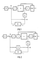
- the invention relates to a hybrid encoder for video signals, in which the data of a video picture are divided into data blocks of equal size, each data block is compared with the corresponding data block of the previous video picture by a subtractor and the corresponding data block of the previous video picture is taken from an image memory and in which the difference block obtained by the subtractor passes through a first operation unit, which subjects the difference block to a matrix transformation and in which this transformation is undone in a feedback path by a second operation unit with the inverse matrix, and the recovered difference block is fed to a first input of an adder , during the second input of the adder data blocks are supplied from the image memory and in which the output of the adder is connected to the data input of the image memory.
- a hybrid encoder with the specified features is described in a conference report (Draft version Document Sim 85/78 Report COST 211-bis Simulation Subgroup Meeting, Swiss, December 10 to 11, 1985) of the COST group.
- a basic circuit diagram of the known hybrid encoder is shown in FIG. 1.
- the main purpose of the coder shown is to convert the video data coming from a video data source into a signal with the lowest possible bit rate, with as little information loss as possible.
- Two coding principles - hence the name hybrid encoder - are used in this process: The interframe principle, in which the correlation between temporally successive video images (this term is used here for full and partial images) is used and the intra-frame principle, in which the correlation of the video data within a video image is used.
- the data must be prepared before the actual coding process.
- This processing is adopted in the hybrid coder of FIG. 1 by a functional unit PP (p re p rocessing).
- the data is transferred to the encoder in blocks.
- Such a video data block contains the data of certain pixels of a video image, which are interpreted as elements of a square number matrix (for the meaning of the terms used here in connection with number matrices, see Wigner, EP: Group Theory; Academic Press New York and London 1959, p. 1 -30).
- a data block can consist of the chrominance values of the first eight pixels of the first eight lines of a video image.
- the functional unit PP divides each video image into data blocks of the same size.
- the decomposition rule also contains the assignment of an identifier to each data block.
- the data block just given as an example could be symbolized and identified, for example, by b11 .
- Data blocks from successive video images that have the same identifier are referred to here as corresponding data blocks.
- a data block for example, the data block b11 to an input of a subtractor SR
- the corresponding data block - symbolized, for example, by b 11 - of the previous video image from an image memory BS is given to the other input of the subtractor SR.
- the subtractor SR forms the difference between two matrices (cf. Wigner lc, p. 7); this difference block is now subjected to further operations.
- the transformation by the unit F corresponds approximately to the Fourier transformation (more precisely, it is a special two-dimensional Fourier transformation) in the acoustic signal transmission: the block D11 can usually be coded with fewer binary digits than the block d11 .
- the transformed signal then passes through a quantizer Q, which again ensures data reduction.
- a buffer memory P is provided so that the entire signal can be transmitted to a receiver at a constant bit rate.
- a multiplexer MUX interleaves the useful signal read out from the buffer memory P with control information, which in the present case is below which are used to set a quantizer on the receiver side (these are adaptive quantizers).
- the signal is also looped back to the input of the hybrid encoder via a feedback path.
- the block D11 changed by the quantizer Q1 is regenerated by a regeneration unit (not shown) to such an extent that it matches the original block D11 except for rounding errors.
- the data block b 1 1 (except for rounding errors) at the output of the adder AR results in the video image just supplied via the processing unit PP.
- This data block is read into it via an input E of the image memory BS and takes on the role of the data block b 11 there , which is now deleted.
- bit rate reduction depends crucially on the design of the quantizer Q. If the quantization intervals are large, this also applies to the bit rate reduction, but the image quality is reduced in a particularly disruptive manner by the high quantization errors. For example, a checkerboard-like pattern can be created on the screen by dividing a video image into blocks stirs or there are constantly changing structures (artifacts) that can lead to the complete distortion of the reproduced image.
- adaptive quantizers i.e. quantizers whose characteristic is changed by the video signal.
- the effort is considerable, among other things, because additional information about the state of the quantizer has to be transmitted to the receiver.
- the invention has for its object to provide a hybrid encoder of the type mentioned, in which a reduction of the transmission bit rate is possible without having to accept the interference caused by quantization errors.
- This object is achieved in that the first operation unit is followed by a third operation unit, which performs a matrix operation with a low-pass character with the transformed blocks of the first operation unit, and in that a fourth operation unit is inserted between the aforementioned output of the image memory and the second input of the adder, with which a matrix operation is performed which has the same effect as the successive matrix operations of the first, third and second operation unit.
- the invention is based on the knowledge that - analogous to the acoustic case - one in his band wide restricted signal with lower bit rate can be transmitted over a given channel.
- the clipping of the frequency bandwidth of the video signal is noticeable on the screen by blurring. However, such blurring is less disturbing than the disturbances described above due to the quantization errors.
- FIG. 2 differs from FIG. 1 only by two operating units, namely T and FTI.
- the designations for the remaining units are the same as in FIG. 1.
- the operation unit T lies between the operation unit F and the quantizer Q, while the operation unit FTI deforms the output signal of the image memory BS in the sense explained below and then to an input of the Adders AR passes.
- the subtractor SR is supplied via the operation unit PP, while at the same time at the output A of the image memory BS the data block b 11 is present.
- the unit T which is assigned a matrix h, makes it the block h t a ⁇ 1d11ah , where h t means the matrix transposed to h (cf. Wigner lc, p. 23).
- a matrix operation with a low-pass character is carried out with the matrix h ; further details will be given below.
- the block specified last arrives at the operational unit IF, which brings about a transformation inverse to the transformation of the unit F; this means that the block ah t a ⁇ 1d11aha ⁇ 1 now appears at the output of the unit IF.
- the low-pass filtered blocks are read into the image memory BS, so an unsharp image is stored and also transmitted. This sharpness of formation is the price to be paid for the suppression of quantization errors.
- the quantizer Q can be a non-adaptive quantizer, for example, or can be omitted entirely if the bit rates are low enough.
- the operating unit F uses the matrix a to carry out a cosine transformation (cf., for example, Pratt, WK: Digital Image Processing; John Wiley & Sons 1978, pp. 242-247).
- the matrix a is therefore known to the person skilled in all details.
- a particularly simple matrix namely a diagonal matrix (cf. Wigner lc, p. 8), can be specified for h .
- Filter matrices that filter the blocks in the spatial area (acoustic analogue: time area) have the same structure as the following auxiliary matrix m :
- the second line of the matrix m From the second line of the matrix m , three elements - here 1, 0, 1 - are shifted one place to the right with every further line; all other elements of the line are zero.
- the first two elements of the first line and the last two elements of the last line consist of ones, while here, too, all other elements consist of zeros.
- the number of lines in the matrix m (it corresponds to the number of columns) is as large as the number of lines or number of columns in the blocks to be processed.
- the matrix w as the matrix with I as the unit matrix, for k less than 1 but greater than or equal to 0.5, a whole class of filter matrices with a low-pass character results.
- Each power of w also results in a matrix with a low-pass character.
- the low-pass filtering can be refined by changing the matrices h and w as a function of the signal, so that the filtering is carried out adaptively. Then, however, additional information must be transmitted to the receiver for decoding. This transmission of the additional information is indicated, for example, by connecting the unit T to the multiplexer MUS. The same connections also exist between the other units with a low-pass effect and the multiplexer MUX; however, they are not shown.
- the setting of, for example, the cut-off frequencies of the units with a low-pass effect depends on the fill level of the buffer memory P and on the so-called displacement vector, a variable which indicates the difference between successive video images due to the movement of the recorded objects and also from the image memory BS (indicated by the connection of the Unit PP with the image memory BS) is determined.
- Information about the fill level of the buffer memory P and the size of the displacement vector are also transmitted to the receiver for proper decoding.
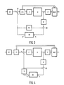
- FIG. 3 A variant of the hybrid encoder according to FIG. 2 is shown in FIG. 3.
- the matrix transformation with low-pass character takes place at the output of the subtractor SR by an operation unit FTI and then the transformation of the difference blocks into the wave number range with the unit F.
- the operation unit FTI at the output of the subtractor SR carries out the low-pass filtering in the spatial area, just like the second unit FTI, which transforms the data blocks from the image memory BS and feeds the adder AR.
- This variant has the advantage that two identical units FTI can be used in the hybrid encoder and therefore, for example, only one transformation matrix needs to be stored.
- Another variant, but not shown, with the same advantage is to have the operation unit F, which performs the Fourier transformation of the data blocks, immediately follow the unit PP in a circuit according to FIG. 2, that is to say the blocks already transformed to the subtractor SR feed. Then another unit T is to be substituted for the unit FTI, while the unit IF is omitted. In this way, only signals in the wave number space are processed in the loop.
- the low-pass filtering of the blocks of the video signal is carried out by a unit T1 before the difference is formed by the subtractor SR.
- Another unit T2 immediately follows the output of the image memory BS. Both units T1 and T2 carry out the low-pass filtering in the spatial area, that is to say contain matrices which formally correspond to the matrix w specified above or powers of these.
- the setting or control of the cut-off frequencies of the units T1 and T2 - as in the other variants with two low-pass units - is initially carried out in such a way that corresponding data blocks experience the same filtering; the cut-off frequencies are the same for both low-pass units.
- a further improvement in the quality of the transmitted images can be achieved without increasing the transmission bit rate if the low-pass effect of the unit T1 is less than the low-pass effect unit T2.
- a lower low-pass effect means, for example, a higher cut-off frequency; the low-pass effect of a unit becomes zero when the cutoff frequency becomes infinitely large.
- the limit frequencies of the units T1 and T2 are controlled, for example by the displacement vector, the limit frequency of the unit T1 must always be selected to be greater than the limit frequency of the unit T2.
- both units T1 and T2 have no effect, that is to say they have infinitely large cutoff frequencies.
- the following empirically found fact is important for the further reasoning: If one carries out the above-mentioned special, areal Fourier transformation with the data blocks coming from the unit PP and also carries out the same transformation with the data blocks that come from the image memory BS, then one finds that between the coefficients that are too high Frequencies (better: wavenumbers) and corresponding data blocks belong to each other, there is only a slight correlation.
- the high frequency components of the blocks that come from the unit PP are therefore statistically independent of the high frequency components of the data blocks that come from the image memory BS.
- the subtractor SR forms the difference between the two blocks, and the difference block is transformed by the unit F Fourier, larger values result for the high frequency components of the difference blocks - because of the statistical independence of the summands - than for each of the blocks alone.
- the high frequency component of the blocks that come from the image memory BS is damped by the unit T2 - which now has a finite cutoff frequency. This improves the image quality on the receiver side because unsuitable portions of the image are no longer used for coding on the transmitter side. Among other things, this leads to a smaller number of bits required for coding the differential blocks.
- the band of the signal to be coded is performed by the operation unit T1. It has to be done in such a way that the cut-off frequency of the unit T1 acting as a low-pass filter is above the cut-off frequency of the unit T2.
- the band limitation of the blocks coming from the unit PP reduces the annoying quantization noise at the expense of image sharpness; however, this disadvantage is less troublesome.
- the low-pass characteristic of the unit T2 is determined both from the degree of correlation between the coefficients of the blocks coming from the unit PP and the blocks coming from the image memory BS and from the low-pass characteristic of the unit T1.
- a variant of a hybrid decoder according to the invention essentially consists of part of the corresponding variant of the hybrid encoder.
- a hybrid decoder contains all units that are in the feedback loop of the corresponding hybrid encoder.
- the hybrid decoder contains, in addition to an input buffer memory, a unit IF for transforming the data blocks back into space, an adder AR an image memory BS and an operation unit FTI for filtering; all of these units are connected to one another in the same way as the corresponding units of the hybrid encoder according to FIG. 2.
- the output of the adder AR on the receiver side is at the same time the output of the hybrid decoder.
- the blocks present here are subjected to a further treatment, which essentially includes the resolution of the block structure, so that the signal can be made visible on a monitor as a result of video images.
Landscapes
- Engineering & Computer Science (AREA)
- Multimedia (AREA)
- Signal Processing (AREA)
- Compression Or Coding Systems Of Tv Signals (AREA)
Applications Claiming Priority (6)
| Application Number | Priority Date | Filing Date | Title |
|---|---|---|---|
| DE3613343 | 1986-04-19 | ||
| DE19863613343 DE3613343A1 (de) | 1986-04-19 | 1986-04-19 | Hybrid-codierer |
| DE3620424 | 1986-06-18 | ||
| DE19863620424 DE3620424A1 (de) | 1986-04-19 | 1986-06-18 | Hybrid-codierer |
| DE3638128 | 1986-11-08 | ||
| DE19863638128 DE3638128A1 (de) | 1986-11-08 | 1986-11-08 | Hybrid-codierer |
Publications (3)
| Publication Number | Publication Date |
|---|---|
| EP0244001A2 true EP0244001A2 (fr) | 1987-11-04 |
| EP0244001A3 EP0244001A3 (en) | 1990-10-10 |
| EP0244001B1 EP0244001B1 (fr) | 1994-01-05 |
Family
ID=27194287
Family Applications (1)
| Application Number | Title | Priority Date | Filing Date |
|---|---|---|---|
| EP87200651A Expired - Lifetime EP0244001B1 (fr) | 1986-04-19 | 1987-04-07 | Codeur hybride pour des signaux vidéo |
Country Status (3)
| Country | Link |
|---|---|
| EP (1) | EP0244001B1 (fr) |
| JP (1) | JPH0832041B2 (fr) |
| DE (1) | DE3788674D1 (fr) |
Cited By (5)
| Publication number | Priority date | Publication date | Assignee | Title |
|---|---|---|---|---|
| AU595872B2 (en) * | 1986-04-14 | 1990-04-12 | N.V. Philips Gloeilampenfabrieken | Image display |
| EP0396360A2 (fr) * | 1989-04-28 | 1990-11-07 | Victor Company Of Japan, Limited | Dispositif de codage intertrame par prédiction d'un signal vidéo |
| EP0414193A2 (fr) * | 1989-08-21 | 1991-02-27 | Mitsubishi Denki Kabushiki Kaisha | Codeur/décodeur à quantification adaptative |
| EP0784408A3 (fr) * | 1996-01-11 | 2000-08-16 | Fujitsu Limited | Codeur et décodeur vidéo |
| FR2828977A1 (fr) * | 2001-08-21 | 2003-02-28 | Nextream Sa | Dispositif et procede d'estimation du niveau de bruit, systeme de reduction de bruit et systeme de codage comprenant un tel dispositif |
Citations (1)
| Publication number | Priority date | Publication date | Assignee | Title |
|---|---|---|---|---|
| DE2703909A1 (de) * | 1975-09-18 | 1978-08-03 | Siemens Ag | Bilduebertragungsanlage |
-
1987
- 1987-04-07 EP EP87200651A patent/EP0244001B1/fr not_active Expired - Lifetime
- 1987-04-07 DE DE87200651T patent/DE3788674D1/de not_active Expired - Lifetime
- 1987-04-20 JP JP62097251A patent/JPH0832041B2/ja not_active Expired - Lifetime
Patent Citations (1)
| Publication number | Priority date | Publication date | Assignee | Title |
|---|---|---|---|---|
| DE2703909A1 (de) * | 1975-09-18 | 1978-08-03 | Siemens Ag | Bilduebertragungsanlage |
Non-Patent Citations (1)
| Title |
|---|
| PROCEEDINGS OF THE IEEE. vol. 73, no. 4, April 1985, NEW YORK US pages 671 - 688; H. SABRI ET AL.: "VIDEO CONFERENCING SYSTEMS" * |
Cited By (10)
| Publication number | Priority date | Publication date | Assignee | Title |
|---|---|---|---|---|
| AU595872B2 (en) * | 1986-04-14 | 1990-04-12 | N.V. Philips Gloeilampenfabrieken | Image display |
| EP0396360A2 (fr) * | 1989-04-28 | 1990-11-07 | Victor Company Of Japan, Limited | Dispositif de codage intertrame par prédiction d'un signal vidéo |
| EP0396360A3 (fr) * | 1989-04-28 | 1991-02-06 | Victor Company Of Japan, Limited | Dispositif de codage intertrame par prédiction d'un signal vidéo |
| US5089889A (en) * | 1989-04-28 | 1992-02-18 | Victor Company Of Japan, Ltd. | Apparatus for inter-frame predictive encoding of video signal |
| EP0414193A2 (fr) * | 1989-08-21 | 1991-02-27 | Mitsubishi Denki Kabushiki Kaisha | Codeur/décodeur à quantification adaptative |
| EP0414193A3 (en) * | 1989-08-21 | 1991-12-27 | Mitsubishi Denki Kabushiki Kaisha | Adaptive quantization coder/decoder |
| EP0784408A3 (fr) * | 1996-01-11 | 2000-08-16 | Fujitsu Limited | Codeur et décodeur vidéo |
| FR2828977A1 (fr) * | 2001-08-21 | 2003-02-28 | Nextream Sa | Dispositif et procede d'estimation du niveau de bruit, systeme de reduction de bruit et systeme de codage comprenant un tel dispositif |
| WO2003019947A1 (fr) * | 2001-08-21 | 2003-03-06 | Nextream France | Dispositif et procede pour evaluer un niveau de bruit, systeme de reduction de bruit et systeme de codage comprenant un tel dispositif |
| US7515638B2 (en) | 2001-08-21 | 2009-04-07 | Nextream France | Device and process for estimating noise level, noise reduction system and coding system comprising such a device |
Also Published As
| Publication number | Publication date |
|---|---|
| JPH0832041B2 (ja) | 1996-03-27 |
| EP0244001A3 (en) | 1990-10-10 |
| JPS631183A (ja) | 1988-01-06 |
| DE3788674D1 (de) | 1994-02-17 |
| EP0244001B1 (fr) | 1994-01-05 |
Similar Documents
| Publication | Publication Date | Title |
|---|---|---|
| DE3613343A1 (de) | Hybrid-codierer | |
| EP0201679B1 (fr) | Procédé de réduction de données d'images pour des signaux de télévision numériques | |
| DE69131533T2 (de) | Datenkompression unter Verwendung eines direkt gesteuerten Quantisierungsprediktors | |
| DE69015695T2 (de) | Einrichtung zur Transformationskodierung. | |
| DE69324090T2 (de) | Intraframefilter für Bildkompressionssysteme | |
| DE69434667T2 (de) | Adaptives codierungs-decodierungsverfahren mit variabler länge für bilddaten | |
| DE68906259T2 (de) | Gerät zur Diskret-Kosinus-Transform-Kodierung digitaler Videosignale. | |
| DE69322501T2 (de) | Verfahren und system zur videokompandierung | |
| DE3124653C2 (fr) | ||
| EP0346766A1 (fr) | Procédé pour la réduction d'artefacts d'enconbrement dans le codage de scène de vidéo par transformation en cosinus discrète avec débit de données réduit | |
| DE69106580T2 (de) | Codieranordnung mit einem Unterbandcoder und Sender mit der Codieranordnung. | |
| DE3542104C2 (de) | Anordnung zur digitalen Signalverarbeitung | |
| DE3426939C2 (de) | Vorrichtung für eine geschlossene prädiktive Quantisierung eines digitalen Vektorsignals | |
| DE3203852C2 (de) | Anordnung zur digitalen Filterung von digitalisierten Chrominanzsignalen in einem Digitalkomponenten-Fernsehsystem | |
| EP0255931B1 (fr) | Procédé de transmission d'un signal vidéo | |
| DE69527770T2 (de) | Bildkodierungsverfahren und -vorrichtung mit Schätzung der Datenmenge | |
| EP0244001B1 (fr) | Codeur hybride pour des signaux vidéo | |
| DE3334541C2 (fr) | ||
| DE69008731T2 (de) | Wortbreitenreduzierungssystem für videosignalverarbeitung und - übertragung. | |
| DE69230047T2 (de) | Fernsehsystem zum Übertragen von Bildsignalen in einem digitalen Format | |
| DE69611987T2 (de) | Übertragungssystem mit zeitabhängigen filterbänken | |
| DE4004857A1 (de) | Einrichtung zur bandbreitenreduzierenden codierung von videosignalen | |
| DE3726601C2 (fr) | ||
| DE3908865C2 (de) | Gerät zur Verarbeitung digitaler Signale | |
| EP0397912A1 (fr) | Méthode et montage pour obtenir le gradient des signaux de sortie d'un réseau donné pour traiter des signaux à temps discret en fonction des paramètres du circuit |
Legal Events
| Date | Code | Title | Description |
|---|---|---|---|
| PUAI | Public reference made under article 153(3) epc to a published international application that has entered the european phase |
Free format text: ORIGINAL CODE: 0009012 |
|
| AK | Designated contracting states |
Kind code of ref document: A2 Designated state(s): DE FR GB IT SE |
|
| PUAL | Search report despatched |
Free format text: ORIGINAL CODE: 0009013 |
|
| RHK1 | Main classification (correction) |
Ipc: H04N 7/13 |
|
| AK | Designated contracting states |
Kind code of ref document: A3 Designated state(s): DE FR GB IT SE |
|
| 17P | Request for examination filed |
Effective date: 19910404 |
|
| 17Q | First examination report despatched |
Effective date: 19920731 |
|
| GRAA | (expected) grant |
Free format text: ORIGINAL CODE: 0009210 |
|
| AK | Designated contracting states |
Kind code of ref document: B1 Designated state(s): DE FR GB IT SE |
|
| REF | Corresponds to: |
Ref document number: 3788674 Country of ref document: DE Date of ref document: 19940217 |
|
| ITF | It: translation for a ep patent filed | ||
| ITTA | It: last paid annual fee | ||
| GBT | Gb: translation of ep patent filed (gb section 77(6)(a)/1977) |
Effective date: 19940408 |
|
| ET | Fr: translation filed | ||
| PLBE | No opposition filed within time limit |
Free format text: ORIGINAL CODE: 0009261 |
|
| STAA | Information on the status of an ep patent application or granted ep patent |
Free format text: STATUS: NO OPPOSITION FILED WITHIN TIME LIMIT |
|
| 26N | No opposition filed | ||
| EAL | Se: european patent in force in sweden |
Ref document number: 87200651.5 |
|
| ITPR | It: changes in ownership of a european patent |
Owner name: CAMBIO RAGIONE SOCIALE;PHILIPS ELECTRONICS N.V. |
|
| REG | Reference to a national code |
Ref country code: FR Ref legal event code: CD |
|
| REG | Reference to a national code |
Ref country code: FR Ref legal event code: CD |
|
| REG | Reference to a national code |
Ref country code: GB Ref legal event code: IF02 |
|
| PGFP | Annual fee paid to national office [announced via postgrant information from national office to epo] |
Ref country code: GB Payment date: 20060425 Year of fee payment: 20 |
|
| PGFP | Annual fee paid to national office [announced via postgrant information from national office to epo] |
Ref country code: FR Payment date: 20060426 Year of fee payment: 20 |
|
| PGFP | Annual fee paid to national office [announced via postgrant information from national office to epo] |
Ref country code: SE Payment date: 20060427 Year of fee payment: 20 |
|
| PGFP | Annual fee paid to national office [announced via postgrant information from national office to epo] |
Ref country code: IT Payment date: 20060430 Year of fee payment: 20 |
|
| PGFP | Annual fee paid to national office [announced via postgrant information from national office to epo] |
Ref country code: DE Payment date: 20060619 Year of fee payment: 20 |
|
| REG | Reference to a national code |
Ref country code: GB Ref legal event code: PE20 |
|
| EUG | Se: european patent has lapsed | ||
| PG25 | Lapsed in a contracting state [announced via postgrant information from national office to epo] |
Ref country code: GB Free format text: LAPSE BECAUSE OF EXPIRATION OF PROTECTION Effective date: 20070406 |