EP0243759A2 - Dispositif d'obturation des embouchures des conduites des attelages automatiques - Google Patents
Dispositif d'obturation des embouchures des conduites des attelages automatiques Download PDFInfo
- Publication number
- EP0243759A2 EP0243759A2 EP87105311A EP87105311A EP0243759A2 EP 0243759 A2 EP0243759 A2 EP 0243759A2 EP 87105311 A EP87105311 A EP 87105311A EP 87105311 A EP87105311 A EP 87105311A EP 0243759 A2 EP0243759 A2 EP 0243759A2
- Authority
- EP
- European Patent Office
- Prior art keywords
- band
- coupling
- section
- line mouth
- mouth
- Prior art date
- Legal status (The legal status is an assumption and is not a legal conclusion. Google has not performed a legal analysis and makes no representation as to the accuracy of the status listed.)
- Granted
Links
Images
Classifications
-
- B—PERFORMING OPERATIONS; TRANSPORTING
- B61—RAILWAYS
- B61G—COUPLINGS; DRAUGHT AND BUFFING APPLIANCES
- B61G5/00—Couplings for special purposes not otherwise provided for
- B61G5/06—Couplings for special purposes not otherwise provided for for, or combined with, couplings or connectors for fluid conduits or electric cables
Definitions
- the invention relates to a device for covering the line mouth at the front end of a line coupling, which is accommodated in the coupling head of an automatic coupling for rail vehicles, with a longitudinally movable, flexible band, which has a portion serving as a protective flap, which in the uncoupled position of the coupling head in front of the
- the line mouth can be adjusted to cover it and can be removed during coupling processes from the line mouth to release it, the band being guided over at least one deflection point deflecting its longitudinal direction.
- the section of the band which can be adjusted in front of the line mouth as a protective flap in the uncoupled state requires special guidance and / or stiffening in order to be able to cover the line mouth reliably; Special springs and / or rods are required for this guidance or stiffening, which results in a complex and sensitive mechanism.
- the invention has for its object to design a device of the type mentioned in such a way that it avoids the shortcomings of the known devices, is particularly simple and requires little effort.
- the band is provided, at least in the region of its section serving as a protective flap, with an elastic transverse corrugation running transversely to its longitudinal direction, which is flattened in band parts located in the region of deflection points, and in that the serving as a protective flap Section of the tape is stable in front of the line mouth due to inherent rigidity.
- the sufficient inherent rigidity of the band is achieved by the transverse corrugation, which ensures that the band is held securely in front of the pipe mouth, even without special guiding and / or stiffening devices.
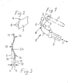
- Fig.l is a dash-dotted line coupling l is shown, which belongs to an automatic coupling of the usual type, not shown, and whose mouth 2, with which it can be coupled to a mating coupling, not shown, faces away from the viewer.
- a section 3 of a flexible band 4 in front of the mouth 2, the section 3 covers rougeei the mouth 2 and thus serves as a protective flap for this.
- the deflection point 5 has several bolts 6 between which the band 4 is passed and of a longitudinal extent in its section 3 in which extends perpendicular to the axial direction of the line coupling 1 a longitudinal direction running approximately parallel to and to the side of the line coupling 1 is deflected.
- the rear end of the band 4 is cut off and not shown; at this end one intervenes Actuating device by means of which the band can be moved in its longitudinal direction in accordance with the direction of the double arrow 7.
- the actuating device can have actuating levers which, when a mating clutch starts, pull the band 4 backwards against the spring force from the position shown until the section 3 slides off the mouth 2 and thus releases the latter for coupling.
- the actuating levers When uncoupling, the actuating levers are released from the counter clutch, and the spring force mentioned can advance the band 4 again into the position shown.
- the actuator can thus receive training as shown in the already mentioned DE-OS 34 35 779.
- section 3 can be guided solely through the deflection point 5 in front of the mouth 2 and that no further guiding and / or stiffening devices are required for the section 3; section 3 is thus held in front of the mouth 2 by its inherent rigidity.
- this In order to give the band 4 the required inherent rigidity, this must be designed at least in the region of its section 3 serving as a protective flap, as described below:
- the band 4 is provided, at least in the region of its section 3, with a transverse corrugation which is elastic or molded into the band 4; the transverse corrugation is illustrated in FIG. 2 by the reference number 8 by reference to the locations of its maximum, lateral and in the longitudinal direction of the band 4 shaped formations.
- the transverse corrugation 8 is formed from the band 4, ie the band 4 is flattened in the region of the deflection point 5 by the bolts 6, as is indicated in FIG. 1; as a result, the longitudinal direction of the band 4 in the deflection point 5 can be deflected easily. Outside the deflection point 5, the band 4 automatically resumes the transverse corrugation 8 due to its elasticity.
- the transverse corrugation 8 runs between lateral delimitation planes 9 and 10, and the lateral ones Edges ll and l2 of the band 4 are located between the delimitation planes 9 and l0 approximately in their central plane l3, the distances a and b of the edges ll and l2 to the delimitation planes 9 and l0 are thus approximately the same.
- the arches of the transverse corrugation 8 are designated in FIG.
- edges 11 and 12 of the band 4 lie in arc sections 14 and 16 directed away from the mouth 2. This design prevents the edges ll or l2 from coming into contact with the mouth 2 and damaging the sealing ring.
- the band 4 has the transverse corrugation 8 at least in the region of its section 3 which can be moved as a cover flap in front of the mouth 2.
- care must be taken to ensure that the band 4 has a reduced inherent rigidity in its area facing away from the section, that is to say it could buckle against the mouth 2 without any special precautions in particular when the section 3 is pushed forward.
- the band 4 can also be provided with the transverse corrugation 4 over its entire length, as a result of which it obtains an inherent stiffness in all of its regions outside the deflection point 5, which it automatically stretches and thus also holds suitable for transmitting thrust forces.
- the band 4 can also be deflected several times, it is only essential that the deflection point 5, which is located on the side of the mouth 2, directs and guides the section 3 in front of the mouth 2, the section 3 thus no further guidance or stiffening is required.
- the deflection point 5 may josei or the like instead of the bolt 6 with rollers. ver be seen, whereby the longitudinal displacement of the band 4 is facilitated.
- the device for covering the line mouth (2) at the front end of a line coupling (l) has a longitudinally movable, flexible band (4), a section (3) of the band (4) serving as a protective flap in the uncoupled state in front of the line mouth (2 ) is adjustable.
- the band (4) is provided at least in its section (3) with a transverse corrugation (8), by means of which it can be held in front of the mouth (2) with inherent rigidity. To deflect the longitudinal direction of the belt (4), the transverse corrugation (8) is flattened in a deflection point (5).
Landscapes
- Engineering & Computer Science (AREA)
- Mechanical Engineering (AREA)
- Clamps And Clips (AREA)
- Package Frames And Binding Bands (AREA)
- Quick-Acting Or Multi-Walled Pipe Joints (AREA)
- Guiding Agricultural Machines (AREA)
Priority Applications (1)
| Application Number | Priority Date | Filing Date | Title |
|---|---|---|---|
| AT87105311T ATE49389T1 (de) | 1986-05-02 | 1987-04-10 | Vorrichtung zum abdecken von leitungsmuendungen an selbsttaetigen kupplungen von schienenfahrzeugen. |
Applications Claiming Priority (2)
| Application Number | Priority Date | Filing Date | Title |
|---|---|---|---|
| DE3614876 | 1986-05-02 | ||
| DE3614876 | 1986-05-02 |
Publications (3)
| Publication Number | Publication Date |
|---|---|
| EP0243759A2 true EP0243759A2 (fr) | 1987-11-04 |
| EP0243759A3 EP0243759A3 (en) | 1988-04-20 |
| EP0243759B1 EP0243759B1 (fr) | 1990-01-10 |
Family
ID=6300012
Family Applications (1)
| Application Number | Title | Priority Date | Filing Date |
|---|---|---|---|
| EP87105311A Expired - Lifetime EP0243759B1 (fr) | 1986-05-02 | 1987-04-10 | Dispositif d'obturation des embouchures des conduites des attelages automatiques |
Country Status (4)
| Country | Link |
|---|---|
| EP (1) | EP0243759B1 (fr) |
| AT (1) | ATE49389T1 (fr) |
| DD (1) | DD269591A5 (fr) |
| DE (1) | DE3761365D1 (fr) |
Cited By (1)
| Publication number | Priority date | Publication date | Assignee | Title |
|---|---|---|---|---|
| CN113353117A (zh) * | 2021-07-19 | 2021-09-07 | 中车眉山车辆有限公司 | 一种自动车钩气路连接器的连通密封结构 |
Family Cites Families (1)
| Publication number | Priority date | Publication date | Assignee | Title |
|---|---|---|---|---|
| DE3435779A1 (de) * | 1984-09-28 | 1986-04-10 | Knorr-Bremse, 1000 Berlin und 8000 München | Vorrichtung zum abdecken von muendungen von leitungen in selbsttaetigen kupplungen von schienenfahrzeugen |
-
1987
- 1987-04-10 EP EP87105311A patent/EP0243759B1/fr not_active Expired - Lifetime
- 1987-04-10 AT AT87105311T patent/ATE49389T1/de not_active IP Right Cessation
- 1987-04-10 DE DE8787105311T patent/DE3761365D1/de not_active Expired - Lifetime
- 1987-04-30 DD DD87302296A patent/DD269591A5/de not_active IP Right Cessation
Cited By (1)
| Publication number | Priority date | Publication date | Assignee | Title |
|---|---|---|---|---|
| CN113353117A (zh) * | 2021-07-19 | 2021-09-07 | 中车眉山车辆有限公司 | 一种自动车钩气路连接器的连通密封结构 |
Also Published As
| Publication number | Publication date |
|---|---|
| EP0243759A3 (en) | 1988-04-20 |
| DD269591A5 (de) | 1989-07-05 |
| ATE49389T1 (de) | 1990-01-15 |
| DE3761365D1 (de) | 1990-02-15 |
| EP0243759B1 (fr) | 1990-01-10 |
Similar Documents
| Publication | Publication Date | Title |
|---|---|---|
| EP0711724B1 (fr) | Dispositif pour séparer des sections tubulaires perforées | |
| EP0274636A1 (fr) | Dispositif auxiliaire facilitant l'ouverture d'une fermeture à glissière pour vêtement de protection | |
| EP0271819B1 (fr) | Dispositif d'obturation d'une fente | |
| DE2240274C3 (de) | Ferngesteuerte Lenkvorrichtung für Fahrzeuge | |
| EP0243759B1 (fr) | Dispositif d'obturation des embouchures des conduites des attelages automatiques | |
| DE2246483B2 (de) | Verfahren zum Dämpfen des Geräusches der Schubdüse eines Strahltriebwerkes eines Luftfahrzeuges | |
| DE2456378B2 (de) | Schutzvorrichtung für eine Werkzeugmaschine | |
| EP0656449A2 (fr) | Dispositif, spécialement pour travailler à des canalisations | |
| EP0266630B1 (fr) | Dispositif pour aspirer des matières fibreuses | |
| DE19823857C1 (de) | Abgas-Absaugvorrichtung für eine Fahrzeughalle | |
| DD295605A5 (de) | Antriebsvorrichtung fuer ein band, dass eine last traegt, verbunden mit einer vorrichtung zum ablenken der last und zur fuehrung des bandes | |
| EP0150236B1 (fr) | Connexion pour une conduite de haute pression | |
| DE29511893U1 (de) | Abgasabsaugvorrichtung für Kraftfahrzeuge | |
| WO2003072277A1 (fr) | Dispositif deflecteur de bande destine a une enrouleuse | |
| EP0229087A1 (fr) | Tuyauterie souple | |
| DE69613180T2 (de) | Hilfsantriebsvorrichtung | |
| DE19502515C2 (de) | Abgas-Absaugschlauch mit Abtrennvorrichtung | |
| DE920403C (de) | Haltevorrichtung fuer Raketen | |
| EP0298508A1 (fr) | Installation pour l'alimentation pneumatique en fibres | |
| DE2219684C3 (de) | Rohrleitungskupplung für eine Mittelpufferkupplung von Schienenfahrzeugen | |
| DE1455228B2 (de) | Automatische Kupplung fur Eisenbahnfahrzeuge | |
| DE7909660U1 (de) | Höhenverstellbare und mit einer Auflaufeinrichtung versehene Zugdeichsel | |
| DE2029318C3 (fr) | ||
| DE2737136A1 (de) | Manschette | |
| EP0238436B1 (fr) | Entraînement pour un chariot de boucles |
Legal Events
| Date | Code | Title | Description |
|---|---|---|---|
| PUAI | Public reference made under article 153(3) epc to a published international application that has entered the european phase |
Free format text: ORIGINAL CODE: 0009012 |
|
| AK | Designated contracting states |
Kind code of ref document: A2 Designated state(s): AT BE CH DE FR IT LI SE |
|
| PUAL | Search report despatched |
Free format text: ORIGINAL CODE: 0009013 |
|
| AK | Designated contracting states |
Kind code of ref document: A3 Designated state(s): AT BE CH DE FR IT LI SE |
|
| 17P | Request for examination filed |
Effective date: 19880316 |
|
| 17Q | First examination report despatched |
Effective date: 19890615 |
|
| GRAA | (expected) grant |
Free format text: ORIGINAL CODE: 0009210 |
|
| AK | Designated contracting states |
Kind code of ref document: B1 Designated state(s): AT BE CH DE FR IT LI SE |
|
| REF | Corresponds to: |
Ref document number: 49389 Country of ref document: AT Date of ref document: 19900115 Kind code of ref document: T |
|
| ITF | It: translation for a ep patent filed | ||
| REF | Corresponds to: |
Ref document number: 3761365 Country of ref document: DE Date of ref document: 19900215 |
|
| ET | Fr: translation filed | ||
| RAP2 | Party data changed (patent owner data changed or rights of a patent transferred) |
Owner name: UNICUPLER GMBH |
|
| REG | Reference to a national code |
Ref country code: CH Ref legal event code: PUE Owner name: UNICUPLER GMBH |
|
| ITPR | It: changes in ownership of a european patent |
Owner name: CESSIONE;UNICUPLER GMBH |
|
| PLBE | No opposition filed within time limit |
Free format text: ORIGINAL CODE: 0009261 |
|
| STAA | Information on the status of an ep patent application or granted ep patent |
Free format text: STATUS: NO OPPOSITION FILED WITHIN TIME LIMIT |
|
| REG | Reference to a national code |
Ref country code: FR Ref legal event code: TP |
|
| 26N | No opposition filed | ||
| ITTA | It: last paid annual fee | ||
| EAL | Se: european patent in force in sweden |
Ref document number: 87105311.2 |
|
| REG | Reference to a national code |
Ref country code: CH Ref legal event code: PUE Owner name: UNICUPLER GMBH |
|
| REG | Reference to a national code |
Ref country code: FR Ref legal event code: TP |
|
| PGFP | Annual fee paid to national office [announced via postgrant information from national office to epo] |
Ref country code: FR Payment date: 20060420 Year of fee payment: 20 |
|
| PGFP | Annual fee paid to national office [announced via postgrant information from national office to epo] |
Ref country code: SE Payment date: 20060424 Year of fee payment: 20 Ref country code: AT Payment date: 20060424 Year of fee payment: 20 |
|
| PGFP | Annual fee paid to national office [announced via postgrant information from national office to epo] |
Ref country code: CH Payment date: 20060425 Year of fee payment: 20 |
|
| PGFP | Annual fee paid to national office [announced via postgrant information from national office to epo] |
Ref country code: BE Payment date: 20060426 Year of fee payment: 20 |
|
| PGFP | Annual fee paid to national office [announced via postgrant information from national office to epo] |
Ref country code: IT Payment date: 20060430 Year of fee payment: 20 |
|
| PGFP | Annual fee paid to national office [announced via postgrant information from national office to epo] |
Ref country code: DE Payment date: 20060626 Year of fee payment: 20 |
|
| REG | Reference to a national code |
Ref country code: CH Ref legal event code: PL |
|
| EUG | Se: european patent has lapsed | ||
| BE20 | Be: patent expired |
Owner name: *KNORR-BREMSE A.G. Effective date: 20070410 Owner name: *UNICUPLER G.M.B.H. Effective date: 20070410 |