EP0243549A2 - Leckabdichtung - Google Patents
Leckabdichtung Download PDFInfo
- Publication number
- EP0243549A2 EP0243549A2 EP86305259A EP86305259A EP0243549A2 EP 0243549 A2 EP0243549 A2 EP 0243549A2 EP 86305259 A EP86305259 A EP 86305259A EP 86305259 A EP86305259 A EP 86305259A EP 0243549 A2 EP0243549 A2 EP 0243549A2
- Authority
- EP
- European Patent Office
- Prior art keywords
- seals
- sealing clamp
- packing
- sealant
- packing seals
- Prior art date
- Legal status (The legal status is an assumption and is not a legal conclusion. Google has not performed a legal analysis and makes no representation as to the accuracy of the status listed.)
- Granted
Links
Images
Classifications
-
- F—MECHANICAL ENGINEERING; LIGHTING; HEATING; WEAPONS; BLASTING
- F16—ENGINEERING ELEMENTS AND UNITS; GENERAL MEASURES FOR PRODUCING AND MAINTAINING EFFECTIVE FUNCTIONING OF MACHINES OR INSTALLATIONS; THERMAL INSULATION IN GENERAL
- F16L—PIPES; JOINTS OR FITTINGS FOR PIPES; SUPPORTS FOR PIPES, CABLES OR PROTECTIVE TUBING; MEANS FOR THERMAL INSULATION IN GENERAL
- F16L23/00—Flanged joints
- F16L23/16—Flanged joints characterised by the sealing means
- F16L23/167—Flanged joints characterised by the sealing means in connection with the appearance or detection of leaks
-
- F—MECHANICAL ENGINEERING; LIGHTING; HEATING; WEAPONS; BLASTING
- F16—ENGINEERING ELEMENTS AND UNITS; GENERAL MEASURES FOR PRODUCING AND MAINTAINING EFFECTIVE FUNCTIONING OF MACHINES OR INSTALLATIONS; THERMAL INSULATION IN GENERAL
- F16L—PIPES; JOINTS OR FITTINGS FOR PIPES; SUPPORTS FOR PIPES, CABLES OR PROTECTIVE TUBING; MEANS FOR THERMAL INSULATION IN GENERAL
- F16L55/00—Devices or appurtenances for use in, or in connection with, pipes or pipe systems
- F16L55/16—Devices for covering leaks in pipes or hoses, e.g. hose-menders
- F16L55/168—Devices for covering leaks in pipes or hoses, e.g. hose-menders from outside the pipe
- F16L55/17—Devices for covering leaks in pipes or hoses, e.g. hose-menders from outside the pipe by means of rings, bands or sleeves pressed against the outside surface of the pipe or hose
- F16L55/172—Devices for covering leaks in pipes or hoses, e.g. hose-menders from outside the pipe by means of rings, bands or sleeves pressed against the outside surface of the pipe or hose the ring, band or sleeve being tightened by a tangentially arranged threaded pin and a nut
-
- F—MECHANICAL ENGINEERING; LIGHTING; HEATING; WEAPONS; BLASTING
- F16—ENGINEERING ELEMENTS AND UNITS; GENERAL MEASURES FOR PRODUCING AND MAINTAINING EFFECTIVE FUNCTIONING OF MACHINES OR INSTALLATIONS; THERMAL INSULATION IN GENERAL
- F16L—PIPES; JOINTS OR FITTINGS FOR PIPES; SUPPORTS FOR PIPES, CABLES OR PROTECTIVE TUBING; MEANS FOR THERMAL INSULATION IN GENERAL
- F16L55/00—Devices or appurtenances for use in, or in connection with, pipes or pipe systems
- F16L55/16—Devices for covering leaks in pipes or hoses, e.g. hose-menders
- F16L55/168—Devices for covering leaks in pipes or hoses, e.g. hose-menders from outside the pipe
- F16L55/175—Devices for covering leaks in pipes or hoses, e.g. hose-menders from outside the pipe by using materials which fill a space around the pipe before hardening
Definitions
- This invention concerns leak sealing and, in particular, packing seals for leak sealing clamps suitable for on line leak sealing.
- Pipeline leaks can occur in several places, such as between flange connections of pipeline ends, between a valve body and a bonnet flange on the pipeline and in the pipeline itself, say in a welded connection.
- Leak Sealing clamps usually made of steel have been used for many years to seal such leaks.
- Various means have been used for forming a seal between the steel clamps and the flanges or pipelines to which they have been fitted. These means usually involve the use. of a flexible metallic or non-metallic seal deformed by compression by the action of clamping bolts or by pipeline pressure but have not been entirely satisfactory.
- the object of this invention is to provide means suitable for sealing between sealing clamps and flanges or pipes, particularly when hot.
- packing seals are provided, suitable for use between a sealing clamp and a flange or pipe being sealed, which fit by compression as well as by bonding to surfaces.
- the preferred packing seals comprise woven or plaited mineral or synthetic fibrous materials impregnated with a thermosetting resin, particularly one that sets at high temperatures.
- suitable fibrous materials for making the packing seals of the invention include asbestos, carbon fibres and aramid fibres.
- suitable thermosetting resins include epoxides, esters, furanes, phenolic and urea formaldehyde resins.
- the preferred packing seal can, therefore, be compressed and the resin can bond it to metal surfaces.
- the preferred packing seals can be used on hot pipelines, whereby the resin will be set by heat from the pipeline.
- any suitable means may be used.
- One preferred means may be by injection of a sealant to compress the seal against a surface.
- the packing seals could be mounted on piston-like members, such as piston rings, with means for urging the piston-like members.in a desired direction.
- Sealing clamps are usually provided as two halves clamped together by bolts through lugs thereof and to accommodate packing seals according to the invention annular grooves may be provided in the inner face of the clamp. Two or more grooves will be provided for packing seals on each side of the leak. Preferably two pairs of packing seals will be provided.
- the sealing clamp may be provided with various ports for injection of sealant and/or pressure relief.
- Injection ports may be provided for compressing the packing seals by means of sealant unless mechanical compression is to be used.
- injection ports may be provided for injecting sealant between the seals of each pair and ports may be provided for pressure relief from a leaking pipeline or flange connection and then for injection of sealant into the leak itself.
- the latter ports will usually be centrally located so that one or more can be used for accurately locating a sealing clamp onto a pair of flanges by means. of a peg through the port to locate in a space between the flanges.
- the adjoining faces of connecting lugs of the sealing clamps may be provided with channels or grooves for sealant and those channels or grooves will be open to a source of sealant, say from between the seals of each pair of packing seals.
- the sealing clamps envisaged herein may also have caulking lips for deformation to meet any uneven contact with or out-of-roundness the pipeline or flanges thereof.
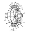
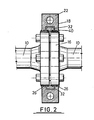
- a pair of pipes 10 connected by nuts and bolts 12 and 14 respectively through holes in facing flanged ends 16 of the pipes 10.
- a steel clamp ring 18 is fitted about the flanges 16. (The method of fitting will be described later)
- the clamp ring 18 is in two halves 18A, 18B connected by lug bolts 20 through lugs 22 of each ring half.
- the clamp ring halves 18A, 18B each have two pairs of annular grooves 24 in their surfaces facing the flanges 16. These annular grooves 24 receive packing seals 26 of woven mineral or synthetic fibre impregnated with a thermosetting resin. Access to the rear of the annular grooves 24 is provided by ports (not shown) through the clamp ring whereby sealant can be injected to force the packing seals 26 onto the flanges 16 and to improve the seal between the packing seals and the clamp ring. This may be particularly important should there be axial misalignment between the flanges or areas of corrosion of the flange surfaces resulting in out-of-roundness.
- the clamp ring 18 has further ports 30 for access between the packing seals of each pair, whereby sealant may be injected.
- sealant may be injected at the faces of lugs 22 are provided with a groove or channel 32 linking the spaces between the pairs of packing seals, whereby sealant injected via the ports 30 can also provide a seal between the adjoining lugs 22.
- the clamp ring also has a central annular channel 34 with further ports 38 giving access thereto for injection of sealant or to act as pressure relief ports.
- the ports 38 may also be used for accurate location of the clamp ring on the flange using dowels through one or more ports to locate in the space between the flanges.
- clamp ring 18 has a caulking lip 40 on each side which can be deformed by hammer blows onto the flange surface to prevent egress of sealant, say in an area of corrosion, if necessary.
- the clamp ring 18 is particularly suitable for on line sealing leaks in flange connections of pipelines, wherein the substance in the pipeline is hot. This will be apparent from the following exemplary prodecure for fitting the clamp ring 18 to the flanges 16.
- the outside diameter of the flanges 16 is accurately measured and the ring clamp inside diameter machined to a slightly larger size.
- the packing seals of woven mineral or synthetic fibre impregnated with high temperature thermosetting resin are then pressed into each of the annular grooves 24 leaving some of the packing proud of the surface of the ring. At each end of the ring halves the packing seal is cut flush therewith.
- the clamp ring halves 18A, B are then fitted onto the flange using a dowel through one of the ports 38 for accurate location, the dowel locating in the space between the flanges.
- the lug bolts 20 are then fitted and used to draw the two ring halves 18A, B into engagement applying a compressive loading to the abutting faces of the lugs.
- Thermosetting sealant is next injected into the ports leading to the annular grooves 24 so forcing the packing seals into compressive contact with the flanges. This compensates for any misalignment or surface irregularities of the flanges. Sealant is then injected into the space between each pair of annular grooves 24 via the ports 30 as well as into the channels 32. This sealant is maintained under pressure while heat from the pipeline. causes the packing seals to bond both to the flanges and to the clamp ring. After bonding the location dowel is removed.
- a suitable leak sealing compound is then injected into the central exhaust ports 38 to finally seal the leak or indeed any other suitable leak sealing process may be used that may be independent of the clamp ring.
- clamp ring 50 here shown is especially intended for use when pipeline flanges are misaligned.
- the clamp ring 50 based on that of Figures 1 and 2 and so similar features have been given the same reference numerals for'simplicity.
- the clamp ring is again in two halves connected by lug bolts through lugs thereof. However, it has only two packing seals 52.
- the packing seals 52 are of woven mineral or synthetic fibre impregnated with thermosetting resin. and are in annular grooves 54 of piston rings 56 themselves in annular grooves 58 of the clamp ring.
- the piston rings 56 are connected to screws 60 radially disposed about the clamp ring 50 whereby the packing seals can be forced into engagement with the flanges 16.
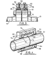
- FIG 4 a leak sealing box clamp 70 is shown fitted to a pipeline 72 leaking at a welded connection 74 therein.
- the box clamp 70 is in two halves only one of which is shown and that partially cutaway to reveal features of the clamp.
- the two halves have lugs 76 connected by lug bolts (not shown) and are relieved centrally at 80.
- the box clamp will be positioned over the pipeline with the leak more or less centrally provided that the areas of the pipeline to each side of the leak are not defective.
- the size of the central relieving may give sufficient latitude for positioning of the box to avoid having to seal on defective areas of the pipeline.
- the box clamp To each side of the area 80 the box clamp has a pair of annular grooves 82 in which are packing seals 84. Ports 86 give access to the grooves 82 for injection of sealant to force the seals 84 onto the pipeline and to the seal between the packing seals and the annular grooves.
- Further injection ports 88 are provided for injecting sealant into the spaces between the seal 84 of each pair and channels 90 linking these spaces.
- the ends of the box clamp 70 are provided with a caulking tip 92.
- the fitting process for the box clamp 70 is basically the same as for the clamp ring of Figure 1 and 2 except that the final injections of sealant is not required.
Landscapes
- Engineering & Computer Science (AREA)
- General Engineering & Computer Science (AREA)
- Mechanical Engineering (AREA)
- Gasket Seals (AREA)
- Glass Compositions (AREA)
- Flanged Joints, Insulating Joints, And Other Joints (AREA)
- Sealing Material Composition (AREA)
- External Artificial Organs (AREA)
Priority Applications (1)
| Application Number | Priority Date | Filing Date | Title |
|---|---|---|---|
| AT86305259T ATE62062T1 (de) | 1986-04-29 | 1986-07-08 | Leckabdichtung. |
Applications Claiming Priority (2)
| Application Number | Priority Date | Filing Date | Title |
|---|---|---|---|
| GB868610508A GB8610508D0 (en) | 1986-04-29 | 1986-04-29 | Leak sealing |
| GB8610508 | 1986-04-29 |
Publications (3)
| Publication Number | Publication Date |
|---|---|
| EP0243549A2 true EP0243549A2 (de) | 1987-11-04 |
| EP0243549A3 EP0243549A3 (en) | 1988-03-23 |
| EP0243549B1 EP0243549B1 (de) | 1991-03-27 |
Family
ID=10597069
Family Applications (1)
| Application Number | Title | Priority Date | Filing Date |
|---|---|---|---|
| EP86305259A Expired - Lifetime EP0243549B1 (de) | 1986-04-29 | 1986-07-08 | Leckabdichtung |
Country Status (5)
| Country | Link |
|---|---|
| EP (1) | EP0243549B1 (de) |
| AT (1) | ATE62062T1 (de) |
| CA (1) | CA1308043C (de) |
| DE (1) | DE3678433D1 (de) |
| GB (2) | GB8610508D0 (de) |
Cited By (10)
| Publication number | Priority date | Publication date | Assignee | Title |
|---|---|---|---|---|
| EP0600345A1 (de) * | 1992-12-01 | 1994-06-08 | FURMANITE GmbH | Leckabdichtungsvorrichtung für Rohrleitungen |
| EP0600344A1 (de) * | 1992-12-01 | 1994-06-08 | FURMANITE GmbH | Leckabdichtungsvorrichtung für Flanschverbindungen |
| CN102329907A (zh) * | 2011-09-30 | 2012-01-25 | 天津钢铁集团有限公司 | 一种新型热风阀法兰密封夹具及其使用方法 |
| WO2012094699A1 (en) * | 2011-01-12 | 2012-07-19 | Rheem Australia Pty Limited | A sealing arrangement for a solar collector enclosure |
| CN104548447A (zh) * | 2014-12-16 | 2015-04-29 | 陈云伟 | 一种带快速补漏装置的消防水带 |
| CN106895187A (zh) * | 2015-12-18 | 2017-06-27 | 中国石油天然气股份有限公司 | 阀门门盖带压堵漏工具 |
| CN112961691A (zh) * | 2021-02-08 | 2021-06-15 | 包头钢铁(集团)有限责任公司 | 一种干熄焦旁通流量中栓泄漏修复的方法 |
| CN114251528A (zh) * | 2021-11-08 | 2022-03-29 | 宋丽华 | 一种预警自处理式钢制管道连接辅助件 |
| CN119332040A (zh) * | 2024-10-23 | 2025-01-21 | 江苏沙钢钢铁有限公司 | 一种下密阀煤气泄漏处理装置 |
| IT202300018735A1 (it) * | 2023-09-12 | 2025-03-12 | Eram Tech S R L | Sistema di tenuta ausiliaria per collegamenti flangiati |
Families Citing this family (4)
| Publication number | Priority date | Publication date | Assignee | Title |
|---|---|---|---|---|
| GB2269870A (en) * | 1992-08-18 | 1994-02-23 | Caradon Terrain | Pipe coupling |
| WO2011082478A1 (en) * | 2010-01-08 | 2011-07-14 | Kerr Huber Industries, Inc. | Pipe repair device |
| WO2012062504A1 (en) | 2010-11-10 | 2012-05-18 | Exxonmobil Chemical Patents Inc. | Flange joint and method for preventing a fluid from leaking out through a flange joint |
| US20240426404A1 (en) * | 2023-06-26 | 2024-12-26 | Saudi Arabian Oil Company | System and method for pipe replacement repair |
Family Cites Families (15)
| Publication number | Priority date | Publication date | Assignee | Title |
|---|---|---|---|---|
| GB740433A (en) * | 1953-11-05 | 1955-11-09 | Pass & Company Ltd E | An improved split collar for jointing or repairing pipes |
| GB763665A (en) * | 1954-10-27 | 1956-12-12 | Herbert Sydney Jeffery | Improvements relating to pipe collars |
| US3467141A (en) * | 1967-01-09 | 1969-09-16 | Joseph B Smith | Flange coupling repair ring |
| US3550638A (en) * | 1968-07-19 | 1970-12-29 | Joseph B Smith | Repair coupling with deformable metal seal |
| US3603616A (en) * | 1969-08-22 | 1971-09-07 | Pipe Line Development Co | Flange coupling repair ring |
| FR2246804A1 (en) * | 1973-10-09 | 1975-05-02 | Marche Marie | Pipe joining or repairing method - involves injecting thermosetting resin into a sleeve over the joint |
| US3954288A (en) * | 1974-03-13 | 1976-05-04 | The Pipe Line Development Co. | Pipe fitting with self-testing seals and method |
| GB1491774A (en) * | 1975-09-04 | 1977-11-16 | Montpelier Foundry Pty Ltd | Pipe coupling |
| GB1523882A (en) * | 1976-03-08 | 1978-09-06 | Bailey & Co Ltd Sir W H | Sealing devices |
| US4049296A (en) * | 1976-05-03 | 1977-09-20 | Team, Inc. | Leak repair clamp |
| EP0029338B1 (de) * | 1979-11-15 | 1985-09-04 | Sibex (Constructions) Limited | Flanschklammer und Abdichtungsverfahren |
| US4323526A (en) * | 1980-06-02 | 1982-04-06 | Rubco Products, Inc. | Method for sealing pipe joints |
| DE3100565C2 (de) * | 1981-01-10 | 1985-10-03 | Abendroth, Dieter, 4179 Weeze | Vorrichtung zur Abdichtung einer unter Druck stehenden Rohrleitung |
| US4568091A (en) * | 1983-06-07 | 1986-02-04 | Team, Inc. | Leak repair clamp with flexible lip seals |
| DE3334836C2 (de) * | 1983-09-27 | 1994-07-28 | Manibs Spezialarmaturen | Muffenförmige Dichtschelle für Gasleitungen |
-
1986
- 1986-04-29 GB GB868610508A patent/GB8610508D0/en active Pending
- 1986-07-08 DE DE8686305259T patent/DE3678433D1/de not_active Expired - Lifetime
- 1986-07-08 AT AT86305259T patent/ATE62062T1/de not_active IP Right Cessation
- 1986-07-08 EP EP86305259A patent/EP0243549B1/de not_active Expired - Lifetime
-
1987
- 1987-02-05 GB GB8702594A patent/GB2189857B/en not_active Expired
- 1987-03-27 CA CA000533199A patent/CA1308043C/en not_active Expired - Lifetime
Cited By (14)
| Publication number | Priority date | Publication date | Assignee | Title |
|---|---|---|---|---|
| EP0600345A1 (de) * | 1992-12-01 | 1994-06-08 | FURMANITE GmbH | Leckabdichtungsvorrichtung für Rohrleitungen |
| EP0600344A1 (de) * | 1992-12-01 | 1994-06-08 | FURMANITE GmbH | Leckabdichtungsvorrichtung für Flanschverbindungen |
| WO2012094699A1 (en) * | 2011-01-12 | 2012-07-19 | Rheem Australia Pty Limited | A sealing arrangement for a solar collector enclosure |
| CN102329907A (zh) * | 2011-09-30 | 2012-01-25 | 天津钢铁集团有限公司 | 一种新型热风阀法兰密封夹具及其使用方法 |
| CN102329907B (zh) * | 2011-09-30 | 2013-05-01 | 天津钢铁集团有限公司 | 一种新型热风阀法兰密封夹具及其使用方法 |
| CN104548447A (zh) * | 2014-12-16 | 2015-04-29 | 陈云伟 | 一种带快速补漏装置的消防水带 |
| CN106895187A (zh) * | 2015-12-18 | 2017-06-27 | 中国石油天然气股份有限公司 | 阀门门盖带压堵漏工具 |
| CN112961691A (zh) * | 2021-02-08 | 2021-06-15 | 包头钢铁(集团)有限责任公司 | 一种干熄焦旁通流量中栓泄漏修复的方法 |
| CN114251528A (zh) * | 2021-11-08 | 2022-03-29 | 宋丽华 | 一种预警自处理式钢制管道连接辅助件 |
| CN114251528B (zh) * | 2021-11-08 | 2023-10-13 | 沈阳北方厚祥不锈钢有限公司 | 一种预警自处理式钢制管道连接辅助件 |
| IT202300018735A1 (it) * | 2023-09-12 | 2025-03-12 | Eram Tech S R L | Sistema di tenuta ausiliaria per collegamenti flangiati |
| WO2025057091A1 (en) * | 2023-09-12 | 2025-03-20 | Eram Technologies S.R.L. | Auxiliary sealing system for flanged connections |
| CN119332040A (zh) * | 2024-10-23 | 2025-01-21 | 江苏沙钢钢铁有限公司 | 一种下密阀煤气泄漏处理装置 |
| CN119332040B (zh) * | 2024-10-23 | 2025-08-15 | 江苏沙钢钢铁有限公司 | 一种下密阀煤气泄漏处理装置 |
Also Published As
| Publication number | Publication date |
|---|---|
| GB8610508D0 (en) | 1986-06-04 |
| EP0243549A3 (en) | 1988-03-23 |
| CA1308043C (en) | 1992-09-29 |
| GB8702594D0 (en) | 1987-03-11 |
| ATE62062T1 (de) | 1991-04-15 |
| GB2189857B (en) | 1989-12-06 |
| GB2189857A (en) | 1987-11-04 |
| EP0243549B1 (de) | 1991-03-27 |
| DE3678433D1 (de) | 1991-05-02 |
Similar Documents
| Publication | Publication Date | Title |
|---|---|---|
| EP0243549B1 (de) | Leckabdichtung | |
| US4171142A (en) | Leak repair clamp | |
| US6305719B1 (en) | Pipe repair clamp | |
| US4049296A (en) | Leak repair clamp | |
| US5421623A (en) | Friction sealed coupling for pipe | |
| US3702199A (en) | Assemblies of tubular members | |
| SU1132799A3 (ru) | Герметичное раструбное соединение труб | |
| US4576401A (en) | Leak repair clamp | |
| CN108240524B (zh) | 可变径管线密封卡具和管线维修方法 | |
| US5553898A (en) | Hot-tapping sleeve | |
| EP0485076B1 (de) | Kupplung | |
| EP0091254A2 (de) | Rohrverbindung und Dichtung | |
| US4620731A (en) | Apparatus for sealing pipe flanges | |
| US6990718B2 (en) | Tee connection to a pipeline | |
| AU2002321600A1 (en) | Tee connection to a pipeline | |
| CA2409709C (en) | Securing shell assemblies to pipelines | |
| US1791810A (en) | Fluid-tight joint | |
| AU2001250504A1 (en) | Securing shell assemblies to pipelines | |
| US2502351A (en) | Pipe coupling | |
| CN112145866A (zh) | 一种管道泄漏修复夹具 | |
| RU2314453C1 (ru) | Способ ремонта дефектного участка действующего трубопровода | |
| JPH0669574U (ja) | 鋳鉄管のメカニカル継手 | |
| RU2155291C1 (ru) | Способ неразъемного соединения металлических труб | |
| CN213598834U (zh) | 一种带压堵漏夹具 | |
| JPS5910471Y2 (ja) | 無頭管とフランジ管との接続装置 |
Legal Events
| Date | Code | Title | Description |
|---|---|---|---|
| PUAI | Public reference made under article 153(3) epc to a published international application that has entered the european phase |
Free format text: ORIGINAL CODE: 0009012 |
|
| AK | Designated contracting states |
Kind code of ref document: A2 Designated state(s): AT BE CH DE FR IT LI LU NL SE |
|
| 17P | Request for examination filed |
Effective date: 19871007 |
|
| PUAL | Search report despatched |
Free format text: ORIGINAL CODE: 0009013 |
|
| AK | Designated contracting states |
Kind code of ref document: A3 Designated state(s): AT BE CH DE FR IT LI LU NL SE |
|
| 17Q | First examination report despatched |
Effective date: 19890518 |
|
| GRAA | (expected) grant |
Free format text: ORIGINAL CODE: 0009210 |
|
| AK | Designated contracting states |
Kind code of ref document: B1 Designated state(s): AT BE CH DE FR IT LI LU NL SE |
|
| PG25 | Lapsed in a contracting state [announced via postgrant information from national office to epo] |
Ref country code: IT Free format text: LAPSE BECAUSE OF FAILURE TO SUBMIT A TRANSLATION OF THE DESCRIPTION OR TO PAY THE FEE WITHIN THE PRE;WARNING: LAPSES OF ITALIAN PATENTS WITH EFFECTIVE DATE BEFORE 2007 MAY HAVE OCCURRED AT ANY TIME BEFORE 2007. THE CORRECT EFFECTIVE DATE MAY BE DIFFERENT FROM THE ONE RECORDED.SCRIBED TIME-LIMIT Effective date: 19910327 Ref country code: AT Effective date: 19910327 Ref country code: SE Effective date: 19910327 Ref country code: LI Effective date: 19910327 Ref country code: CH Effective date: 19910327 |
|
| REF | Corresponds to: |
Ref document number: 62062 Country of ref document: AT Date of ref document: 19910415 Kind code of ref document: T |
|
| ET | Fr: translation filed | ||
| REF | Corresponds to: |
Ref document number: 3678433 Country of ref document: DE Date of ref document: 19910502 |
|
| REG | Reference to a national code |
Ref country code: CH Ref legal event code: PL |
|
| PG25 | Lapsed in a contracting state [announced via postgrant information from national office to epo] |
Ref country code: LU Free format text: LAPSE BECAUSE OF NON-PAYMENT OF DUE FEES Effective date: 19910731 |
|
| PLBE | No opposition filed within time limit |
Free format text: ORIGINAL CODE: 0009261 |
|
| STAA | Information on the status of an ep patent application or granted ep patent |
Free format text: STATUS: NO OPPOSITION FILED WITHIN TIME LIMIT |
|
| 26N | No opposition filed | ||
| PGFP | Annual fee paid to national office [announced via postgrant information from national office to epo] |
Ref country code: DE Payment date: 20050630 Year of fee payment: 20 |
|
| PGFP | Annual fee paid to national office [announced via postgrant information from national office to epo] |
Ref country code: NL Payment date: 20050703 Year of fee payment: 20 |
|
| PGFP | Annual fee paid to national office [announced via postgrant information from national office to epo] |
Ref country code: FR Payment date: 20050708 Year of fee payment: 20 |
|
| PGFP | Annual fee paid to national office [announced via postgrant information from national office to epo] |
Ref country code: BE Payment date: 20050913 Year of fee payment: 20 |
|
| PG25 | Lapsed in a contracting state [announced via postgrant information from national office to epo] |
Ref country code: NL Free format text: LAPSE BECAUSE OF EXPIRATION OF PROTECTION Effective date: 20060708 |
|
| NLV7 | Nl: ceased due to reaching the maximum lifetime of a patent |
Effective date: 20060708 |
|
| BE20 | Be: patent expired |
Owner name: *FURMANITE INTERNATIONAL LTD Effective date: 20060708 |