EP0243537A2 - Magasin d'outils - Google Patents
Magasin d'outils Download PDFInfo
- Publication number
- EP0243537A2 EP0243537A2 EP86116544A EP86116544A EP0243537A2 EP 0243537 A2 EP0243537 A2 EP 0243537A2 EP 86116544 A EP86116544 A EP 86116544A EP 86116544 A EP86116544 A EP 86116544A EP 0243537 A2 EP0243537 A2 EP 0243537A2
- Authority
- EP
- European Patent Office
- Prior art keywords
- chain
- tool
- tool magazine
- magazine according
- carrier
- Prior art date
- Legal status (The legal status is an assumption and is not a legal conclusion. Google has not performed a legal analysis and makes no representation as to the accuracy of the status listed.)
- Granted
Links
Images

Classifications
-
- B—PERFORMING OPERATIONS; TRANSPORTING
- B23—MACHINE TOOLS; METAL-WORKING NOT OTHERWISE PROVIDED FOR
- B23Q—DETAILS, COMPONENTS, OR ACCESSORIES FOR MACHINE TOOLS, e.g. ARRANGEMENTS FOR COPYING OR CONTROLLING; MACHINE TOOLS IN GENERAL CHARACTERISED BY THE CONSTRUCTION OF PARTICULAR DETAILS OR COMPONENTS; COMBINATIONS OR ASSOCIATIONS OF METAL-WORKING MACHINES, NOT DIRECTED TO A PARTICULAR RESULT
- B23Q3/00—Devices holding, supporting, or positioning work or tools, of a kind normally removable from the machine
- B23Q3/155—Arrangements for automatic insertion or removal of tools, e.g. combined with manual handling
- B23Q3/157—Arrangements for automatic insertion or removal of tools, e.g. combined with manual handling of rotary tools
- B23Q3/15713—Arrangements for automatic insertion or removal of tools, e.g. combined with manual handling of rotary tools a transfer device taking a single tool from a storage device and inserting it in a spindle
- B23Q3/1572—Arrangements for automatic insertion or removal of tools, e.g. combined with manual handling of rotary tools a transfer device taking a single tool from a storage device and inserting it in a spindle the storage device comprising rotating or circulating storing means
- B23Q3/15722—Rotary discs or drums
-
- Y—GENERAL TAGGING OF NEW TECHNOLOGICAL DEVELOPMENTS; GENERAL TAGGING OF CROSS-SECTIONAL TECHNOLOGIES SPANNING OVER SEVERAL SECTIONS OF THE IPC; TECHNICAL SUBJECTS COVERED BY FORMER USPC CROSS-REFERENCE ART COLLECTIONS [XRACs] AND DIGESTS
- Y10—TECHNICAL SUBJECTS COVERED BY FORMER USPC
- Y10T—TECHNICAL SUBJECTS COVERED BY FORMER US CLASSIFICATION
- Y10T29/00—Metal working
- Y10T29/51—Plural diverse manufacturing apparatus including means for metal shaping or assembling
- Y10T29/5104—Type of machine
- Y10T29/5105—Drill press
- Y10T29/5107—Drilling and other
-
- Y—GENERAL TAGGING OF NEW TECHNOLOGICAL DEVELOPMENTS; GENERAL TAGGING OF CROSS-SECTIONAL TECHNOLOGIES SPANNING OVER SEVERAL SECTIONS OF THE IPC; TECHNICAL SUBJECTS COVERED BY FORMER USPC CROSS-REFERENCE ART COLLECTIONS [XRACs] AND DIGESTS
- Y10—TECHNICAL SUBJECTS COVERED BY FORMER USPC
- Y10T—TECHNICAL SUBJECTS COVERED BY FORMER US CLASSIFICATION
- Y10T483/00—Tool changing
- Y10T483/18—Tool transfer to or from matrix
- Y10T483/1818—Matrix including means to project tool for transfer
Definitions
- the invention relates to a tool magazine of the type specified in the preamble of claim 1.
- a tool magazine generally supplies at least two machining spindles with the same tools, which must then also be stored in the magazine in a correspondingly large number.
- the object of the invention is to provide a tool magazine for program-controlled machine tools, the storage capacity of which can be adapted to the machining and operating conditions and which enables improved utilization of the machine tool.
- the subdivision of the tool carrier e.g. of the plate, the chain or the like.
- the tools that are used particularly frequently and are subject to high stress when machining a single workpiece can be combined in one or certain segments and automatically replaced as a whole by exchanging these segments, which reduces the set-up times accordingly.
- the tools required for machining a workpiece type in one or more specific segments and the tools required for other workpiece types in other specific magazine segments.
- multi-spindle automatic machines in which the tools for the individual spindles can also be arranged interchangeably in the magazine.
- the plate-shaped carriers can be assembled from individual segments, each segment being fixed in the plate by means of a holder and secured with the aid of a suitable locking device and being able to be removed after it has been released.
- Each segment can have one or more receptacles for the tools or their cones.
- chain magazines the chain can be released bar coupled individual links or be composed of chain sections of a predetermined length.
- a device arranged, for example, in the rear part of the chain orbit removes the previously selected chain links and / or the chain sections from the chain assembly and replaces them automatically with chain sections previously equipped with new workpieces.
- the magazine segments or sections can be prepared in the workshop and provided directly on the machine tool, so that they can automatically be used against the "used" tools according to the respective control program equipped magazine segments can be exchanged. This significantly reduces the number of necessary interventions in the machining process of the machine tool and thus also increases their performance. Furthermore, the degree of automation of complex manufacturing systems can also be increased in a relatively simple way, because the prepared magazine segments e.g. can be automatically promoted in their deployments on self-driving floor conveyors.
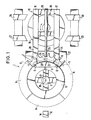
- the magazine plate consists of a support cross 4 attached to a central column 3, a rigid support ring 5, which is rigidly attached to the ends of the support cross struts, and four ring segments ten 6, which form the ring-shaped tool carrier in the assembled state and each have a plurality of tool holders 7 on their outer edge with clamping or snap-in holders for the tool cone.
- Each of the four ring segments 6 can be removed and installed individually from the magazine. In the installed state shown in Fig. 1, locking elements 8 are effective between the support ring 5 and each of the segments which, for. B.
- clamping bolts in the form of common in machine tool clamping bolts, whose hydraulic cylinders are installed in the support ring 5 and are connected via channels 9 with 3 in the column 3 pressure oil channels 10 in connection.
- clamping bolts other fastening elements can also be used for fixing the ring segments to the support ring and also with one another, which can be actuated mechanically, hydraulically, pneumatically or also electrically and ensure a sufficiently dimensionally stable and vibration-free mounting of the ring segments on the support ring or among one another.
- 1 are pivotable bolt 11 for mutual support and additional mounting of two adjacent ring segments indicated by dash-dotted lines.
- the magazine plate is rotated by means of a drive motor (not shown) until the selected tool or an empty position in the change position W is opposite the tool changer 12.
- a drive motor not shown
- the function and mode of operation of the plate magazine corresponds to the usual designs.
- a turntable 15 serves as the transfer device for the individual segments, on which two guide rails 16, 17 are mounted in parallel next to one another and are mutually stiffened by cross struts 18, 19.
- the turntable 15 can be rotated in both directions of rotation by at least 180 ° by means of a drive (not shown).
- the two guide rails 16, 17 are aligned with stationary rail sections 20, 21, which are, for example, fixedly mounted on the support structure 22 of the magazine plate 5, for example on a part of the headstock.
- These guide rail sections 20, 21 extend to below the edge of the magazine plate or the ring segment 6. At its radially inner edge, this ring segment 6 has a downwardly extending ring segment-shaped extension 22 ⁇ , which is shown in broken lines in FIG. 1.
- an opening 23 is centrally provided for the engagement of a locking hook or bolt 24 at the end of a piston rod 25.
- the piston rod 25 is part of a hydraulic pressure cylinder unit 26 which is mounted on the turntable 15 and pressurized oil is supplied via lines, not shown.
- a pair of fixed guide rails 27, 28 and 29, 30 On both sides of the turntable 15 ends a pair of fixed guide rails 27, 28 and 29, 30. These guide rails 27 to 30 are arranged and designed so that they are flush with the two guide rails 16, 17 of the turntable 15 when the latter is wired from its position shown by 90 ° in one direction or the other.
- the piston 25 of the cylinder unit 26 is extended until the hook 24 engages in the recess 23 at its free end and is fixed there by suitable means, for example by a spring clamp .
- the clamping cartridges 8 are pressurized with pressure oil via line 9 and thereby released.
- the now released segment 6 is pulled onto a pallet (not shown in FIG. 1) and brought together with this on the rails 20, 21 to the turntable 15.
- the turntable 15 By subsequently rotating the turntable 15 until it is aligned with the pair of rails 25, 28 or 29, 30 and then extending the piston rod 25, the magazine segment 6, which contains the used tools, is brought into a storage position.
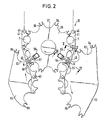
- the embodiment shown in FIG. 2 is a chain magazine in which an endless chain 35 containing the tool holders runs over several chain wheels 36, only one of which is shown.
- the selected tool holders 7 reach the change position by means of a program-controlled drive of at least one of the chain wheels 36.
- the endless chain 35 containing the tool holders 7 is composed of a plurality of chain sections which are detachably connected to one another by specially designed pivot pins.
- Each chain wheel 36 has semicircular cutouts 37 on its outer circumference and semicircular recesses 38 in the intermediate webs delimited by these cutouts 37, in which spring pliers 39 are seated. These spring pliers 39 serve as fixing elements for the joint pins 40 connecting the chain links 41.
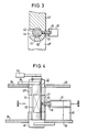
- each hinge pin 40 is flattened on both sides in its central section 42.
- Each chain link 41 has in the region of its one hinge eye 43 a radial cutout 44 transverse to the longitudinal axis of the link, the width of which is slightly larger than the diameter of the bolt shaft in the flattened section 42.
- the cutout 44 diametrically opposite a pin 45 is fixed in the chain link 41 ⁇ (Fig. 3, 4), which is aligned transversely to the longitudinal axis of the link and has a thickened head 46 at its free end.
- an anti-rotation device for the hinge pin 40 in the form of a spring-loaded pin 47 is provided at one end of each chain link 41 ⁇ , which with its crowned end resiliently engages in at least one depression in the inner surface of one hinge pin head 48.
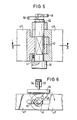
- two transverse pins 49, 50 are fastened at a mutual acute angle transversely to the longitudinal axis of the bolt (cf. FIGS. 5 and 6).
- two further chain wheels 51, 52 are located directly next to the chain wheel 36, of which the left chain wheel in FIG. 2 carries a new chain section to be installed in the endless chain and the right chain wheel in FIG. 2 for removing one chain section to be removed from the endless chain.
- a linear motor designed as a pressure medium cylinder 53 is arranged in a stationary manner radially to the chain wheel 36, on the piston rod 54 of which a slide 55 is fastened.
- This linear drive 53 also shown in FIG. 6, acts on the transverse pin 49 fastened to the free end of the respective hinge pin 40 in order to twist the hinge pin 40 about its longitudinal axis.
- Another linear drive 56 of the same type is arranged radially to the sprocket 36 in a fixed position at point N in FIG. 2, on the piston rod 57 of which a slide 58 is also fastened, which engages on the transverse pin 50 of the joint pin 40 and rotates the latter about its longitudinal axis in the opposite direction.
- each chain wheel 36, 51, 52 consists of two uniformly shaped plates or disks, which are arranged at an axial distance corresponding to the chain link height and are fastened on shafts. Between the two plates of the chain wheels 36 and 52, pliers 61 are fastened on bases 60 (see FIG. 4), which encompass the thickened heads 46 of the cross pins 45.
- each sprocket 51, 52 in each plate on the outer circumference has semicircular cutouts 62, 63 and semicircular recesses 64, 65 with spring pliers 66 fixed therein, which correspond to the elements 37 to 39 of the sprocket 36 in terms of mode of operation and shape.
- the hinge pin 40 rotates by a predetermined amount so that the two flat side surfaces of its flattened central shaft section 42 are aligned parallel to the boundary surfaces of the radial cutout, as shown in FIG. 3.
- the pliers 61 attached to the chain wheel 52 grip the thickened head 46 of the projecting pin 45 (FIGS. 3, 4).
- the pliers 61 engaging behind the thickened head 46 hold the incoming chain link 41 ⁇ on the outer circumference of the sprocket 52, the pivot pin 42 simultaneously sliding out of the radial cutout 44 of the chain link 41.
- a certain chain section the length of which corresponds to the center distance of the two chain wheels 70, 71, can be replaced at the same time.
- the construction and function of the two sprockets 70, 71 corresponds to that of the sprocket 36 in FIG. 2.
- Tenbolzen serve two linear drives 53 of the same construction as the linear drive 53 in Fig. 2.
- the chain section 73 detached from the endless chain 35 is taken over by a holder 74 which has cross webs 75, 76 with corresponding mounting brackets and is mounted on a self-propelled carriage or the like can be.
- the transfer and change operations essentially correspond to those of the exemplary embodiment according to FIGS. 2 to 6.
- FIGS. 1 and 2 can be combined with one another in such a way that an endless chain with tool holders is mounted on the outer circumference of the magazine plate, the individual sections of which are then exchanged in a suitable manner in accordance with the embodiment according to FIG. 2.
Landscapes
- Engineering & Computer Science (AREA)
- Mechanical Engineering (AREA)
- Automatic Tool Replacement In Machine Tools (AREA)
Applications Claiming Priority (2)
| Application Number | Priority Date | Filing Date | Title |
|---|---|---|---|
| DE3613206 | 1986-04-18 | ||
| DE19863613206 DE3613206A1 (de) | 1986-04-18 | 1986-04-18 | Werkzeugmagazin |
Publications (3)
| Publication Number | Publication Date |
|---|---|
| EP0243537A2 true EP0243537A2 (fr) | 1987-11-04 |
| EP0243537A3 EP0243537A3 (en) | 1989-03-15 |
| EP0243537B1 EP0243537B1 (fr) | 1991-07-17 |
Family
ID=6299033
Family Applications (1)
| Application Number | Title | Priority Date | Filing Date |
|---|---|---|---|
| EP86116544A Expired - Lifetime EP0243537B1 (fr) | 1986-04-18 | 1986-11-28 | Magasin d'outils |
Country Status (4)
| Country | Link |
|---|---|
| US (1) | US4835837A (fr) |
| EP (1) | EP0243537B1 (fr) |
| JP (1) | JPS62251039A (fr) |
| DE (2) | DE3613206A1 (fr) |
Cited By (1)
| Publication number | Priority date | Publication date | Assignee | Title |
|---|---|---|---|---|
| DE4304361A1 (de) * | 1993-02-13 | 1994-08-18 | Chiron Werke Gmbh | Verfahren zum Werkzeugwechsel und Werkzeugmaschine zur Durchführung des Verfahrens |
Families Citing this family (11)
| Publication number | Priority date | Publication date | Assignee | Title |
|---|---|---|---|---|
| DE3715874C1 (de) * | 1987-05-01 | 1988-10-13 | Werner & Kolb Werkzeugmasch | Einrichtung zum Wechseln von Werkzeugen eines numerisch gesteuerten Bearbeitungszentrums |
| DE3817256A1 (de) * | 1988-05-20 | 1989-11-23 | Werner & Kolb Werkzeugmasch | Verfahren und vorrichtung zum schnellen ein- und austauschen von werkzeugen bei einer numerisch gesteuerten werkzeugmaschine |
| US5424621A (en) * | 1993-08-03 | 1995-06-13 | Industrial Technology Research Institute | Parallel conjugate cam type tool magazine mechanism |
| US5672145A (en) * | 1996-06-27 | 1997-09-30 | Bridgeport Machines Inc. | Tool carousel |
| DE19708096A1 (de) * | 1997-02-28 | 1998-09-03 | Hueller Hille Gmbh | Bearbeitungszentrum |
| DE69729850T2 (de) * | 1997-03-11 | 2005-08-25 | Posalux S.A. | Werkzeugmaschine mit einem Werkzeugmagazin mit erhöhter Kapazität und Werkzeugmagazin zum Ausrüsten einer Werkzeugmaschine |
| GB2375061B (en) * | 1997-09-12 | 2003-01-29 | Bridgeport Machines Ltd | Drive mechanism for a tool carousel wheel |
| EP1122008A1 (fr) * | 2000-02-02 | 2001-08-08 | Maschinenfabrik Berthold Hermle Aktiengesellschaft | Machine d'usinage avec un magasin rotatif pour le rangement d'outils |
| EP1122023A1 (fr) * | 2000-02-02 | 2001-08-08 | Maschinenfabrik Berthold Hermle Aktiengesellschaft | Machine d'usinage pour tourner et fraiser |
| DE10144605A1 (de) * | 2001-09-11 | 2003-03-27 | Heller Geb Gmbh Maschf | Verfahren zum Bestücken von Werkzeugmagazinen einer Vorrichtung zum Bearbeiten von Werkstücken |
| US20070152814A1 (en) * | 2005-12-29 | 2007-07-05 | Arinc Inc. | Systems and methods for autonomous data acquisition, sensor integration and information transmission in a lightweight device |
Family Cites Families (9)
| Publication number | Priority date | Publication date | Assignee | Title |
|---|---|---|---|---|
| US3715801A (en) * | 1969-03-04 | 1973-02-13 | Y Sato | Tool changer for machine tool |
| JPS5633215B2 (fr) * | 1973-07-28 | 1981-08-01 | ||
| US4306350A (en) * | 1980-05-12 | 1981-12-22 | Kearney & Trecker Corporation | Automatic tool changer and tool storage arrangement for machine tool |
| DE3316999A1 (de) * | 1982-08-05 | 1984-02-09 | VEB Werkzeugmaschinenkombinat "Fritz Heckert" Karl-Marx-Stadt, DDR 9030 Karl-Marx-Stadt | Vorrichtung zur speicherung von werkzeugen einer automatischen werkzeugmaschine |
| US4590662A (en) * | 1982-09-03 | 1986-05-27 | Makino Milling Machine Co., Ltd. | Tool changing machine of machine tool |
| US4577389A (en) * | 1983-04-19 | 1986-03-25 | Textron, Inc. | Automatic tool changer |
| FR2556262B1 (fr) * | 1983-12-09 | 1987-02-20 | Ressencourt Hubert | La presente invention concerne un centre de faconnage de materiaux en feuilles a commande numerique |
| HU190754B (en) * | 1984-02-14 | 1986-11-28 | Tajnafoel,Jozsef,Hu | Multiple-spindle machining centre |
| DD232858A1 (de) * | 1984-12-27 | 1986-02-12 | Mikromat Dresden Betrieb | Vorrichtung zur speicherung von werkzeugen an werkzeugmaschinen |
-
1986
- 1986-04-18 DE DE19863613206 patent/DE3613206A1/de not_active Ceased
- 1986-11-28 DE DE8686116544T patent/DE3680327D1/de not_active Expired - Fee Related
- 1986-11-28 EP EP86116544A patent/EP0243537B1/fr not_active Expired - Lifetime
-
1987
- 1987-01-26 JP JP62015887A patent/JPS62251039A/ja active Pending
- 1987-03-27 US US07/031,532 patent/US4835837A/en not_active Expired - Fee Related
Cited By (2)
| Publication number | Priority date | Publication date | Assignee | Title |
|---|---|---|---|---|
| DE4304361A1 (de) * | 1993-02-13 | 1994-08-18 | Chiron Werke Gmbh | Verfahren zum Werkzeugwechsel und Werkzeugmaschine zur Durchführung des Verfahrens |
| US5474514A (en) * | 1993-02-13 | 1995-12-12 | Chiron-Werke Gmbh & Co. Kg | Method and machine tool for changing tools |
Also Published As
| Publication number | Publication date |
|---|---|
| DE3613206A1 (de) | 1987-10-22 |
| EP0243537B1 (fr) | 1991-07-17 |
| JPS62251039A (ja) | 1987-10-31 |
| DE3680327D1 (de) | 1991-08-22 |
| EP0243537A3 (en) | 1989-03-15 |
| US4835837A (en) | 1989-06-06 |
Similar Documents
| Publication | Publication Date | Title |
|---|---|---|
| DE3818001C3 (de) | Stanzmaschine mit ein- und auswechselbarem Stanzwerkzeug und mit einem Werkstückvorschub | |
| DE69918246T2 (de) | Tragbare Drehmaschinen | |
| DE3049495C2 (fr) | ||
| DE3902470C2 (fr) | ||
| EP0243537B1 (fr) | Magasin d'outils | |
| EP2567783B1 (fr) | Machine à meuler | |
| EP1179415A2 (fr) | Dispositif longitudinal pour le travail de carton ondulé | |
| DE2325629A1 (de) | Werkzeugspeichermagazin | |
| DE2338617A1 (de) | Schweissmaschine mit zerlegbarer saeule | |
| DE2230144A1 (de) | Werkzeugsupport mit darin lotrecht verfahrbarem meisselschieber mit einem dem meisselschieber zugeordneten werkzeugwechsler | |
| DE3327512C2 (fr) | ||
| DE2303198B2 (de) | Vorrichtung zum automatischen, gleichzeitigen und kontinuierlichen Schweißen von mehreren Kraftfahrzeugrädern oder dergleichen Werkstücken | |
| EP0290469B1 (fr) | Dispositif pour l'usinage automatique de pieces ayant des formes differentes | |
| DE1777294A1 (de) | Werkzeugmaschine | |
| DE3504769A1 (de) | Selbstzentrierender schnellwechsel-schneidwerkzeugeinbau | |
| DE3501113C2 (fr) | ||
| DE4031997C2 (fr) | ||
| DE3439324A1 (de) | Werkzeugmaschine fuer verschiedene bearbeitungsvorgaenge | |
| EP3682990B1 (fr) | Dispositif de sécurité | |
| DE19700496A1 (de) | Formmaschine mit Roller und Gipsformenwechsler | |
| EP0137117B1 (fr) | Dispositif changeur d'outils comprenant un appareil pour le transfert des têtes d'outils | |
| DE202010016228U1 (de) | Vorrichtung zum automatischen Werkzeugwechsel | |
| DE3316999A1 (de) | Vorrichtung zur speicherung von werkzeugen einer automatischen werkzeugmaschine | |
| DE102016013333B4 (de) | Werkzeugwechselvorrichtung für eine Werkzeugmaschine, insbesondere eine Werkzeugmaschine zur spanenden Bearbeitung eines Werkstücks | |
| EP0129859B1 (fr) | Machine-outil, particulièrement presse à découpage revolver |
Legal Events
| Date | Code | Title | Description |
|---|---|---|---|
| PUAI | Public reference made under article 153(3) epc to a published international application that has entered the european phase |
Free format text: ORIGINAL CODE: 0009012 |
|
| AK | Designated contracting states |
Kind code of ref document: A2 Designated state(s): CH DE FR GB IT LI |
|
| PUAL | Search report despatched |
Free format text: ORIGINAL CODE: 0009013 |
|
| AK | Designated contracting states |
Kind code of ref document: A3 Designated state(s): CH DE FR GB IT LI |
|
| 17P | Request for examination filed |
Effective date: 19890329 |
|
| 17Q | First examination report despatched |
Effective date: 19900510 |
|
| GRAA | (expected) grant |
Free format text: ORIGINAL CODE: 0009210 |
|
| AK | Designated contracting states |
Kind code of ref document: B1 Designated state(s): CH DE FR GB IT LI |
|
| ITF | It: translation for a ep patent filed | ||
| ET | Fr: translation filed | ||
| GBT | Gb: translation of ep patent filed (gb section 77(6)(a)/1977) | ||
| REF | Corresponds to: |
Ref document number: 3680327 Country of ref document: DE Date of ref document: 19910822 |
|
| PGFP | Annual fee paid to national office [announced via postgrant information from national office to epo] |
Ref country code: FR Payment date: 19910826 Year of fee payment: 6 |
|
| PGFP | Annual fee paid to national office [announced via postgrant information from national office to epo] |
Ref country code: CH Payment date: 19910930 Year of fee payment: 6 |
|
| PGFP | Annual fee paid to national office [announced via postgrant information from national office to epo] |
Ref country code: GB Payment date: 19911114 Year of fee payment: 6 |
|
| PGFP | Annual fee paid to national office [announced via postgrant information from national office to epo] |
Ref country code: DE Payment date: 19920120 Year of fee payment: 6 |
|
| PLBE | No opposition filed within time limit |
Free format text: ORIGINAL CODE: 0009261 |
|
| STAA | Information on the status of an ep patent application or granted ep patent |
Free format text: STATUS: NO OPPOSITION FILED WITHIN TIME LIMIT |
|
| 26N | No opposition filed | ||
| PG25 | Lapsed in a contracting state [announced via postgrant information from national office to epo] |
Ref country code: GB Effective date: 19921128 |
|
| PG25 | Lapsed in a contracting state [announced via postgrant information from national office to epo] |
Ref country code: LI Effective date: 19921130 Ref country code: CH Effective date: 19921130 |
|
| GBPC | Gb: european patent ceased through non-payment of renewal fee |
Effective date: 19921128 |
|
| PG25 | Lapsed in a contracting state [announced via postgrant information from national office to epo] |
Ref country code: FR Effective date: 19930730 |
|
| REG | Reference to a national code |
Ref country code: CH Ref legal event code: PL |
|
| PG25 | Lapsed in a contracting state [announced via postgrant information from national office to epo] |
Ref country code: DE Effective date: 19930803 |
|
| REG | Reference to a national code |
Ref country code: FR Ref legal event code: ST |
|
| PG25 | Lapsed in a contracting state [announced via postgrant information from national office to epo] |
Ref country code: IT Free format text: LAPSE BECAUSE OF NON-PAYMENT OF DUE FEES;WARNING: LAPSES OF ITALIAN PATENTS WITH EFFECTIVE DATE BEFORE 2007 MAY HAVE OCCURRED AT ANY TIME BEFORE 2007. THE CORRECT EFFECTIVE DATE MAY BE DIFFERENT FROM THE ONE RECORDED. Effective date: 20051128 |