EP0243537A2 - Tool magazine - Google Patents
Tool magazine Download PDFInfo
- Publication number
- EP0243537A2 EP0243537A2 EP86116544A EP86116544A EP0243537A2 EP 0243537 A2 EP0243537 A2 EP 0243537A2 EP 86116544 A EP86116544 A EP 86116544A EP 86116544 A EP86116544 A EP 86116544A EP 0243537 A2 EP0243537 A2 EP 0243537A2
- Authority
- EP
- European Patent Office
- Prior art keywords
- chain
- tool
- tool magazine
- magazine according
- carrier
- Prior art date
- Legal status (The legal status is an assumption and is not a legal conclusion. Google has not performed a legal analysis and makes no representation as to the accuracy of the status listed.)
- Granted
Links
Images

Classifications
-
- B—PERFORMING OPERATIONS; TRANSPORTING
- B23—MACHINE TOOLS; METAL-WORKING NOT OTHERWISE PROVIDED FOR
- B23Q—DETAILS, COMPONENTS, OR ACCESSORIES FOR MACHINE TOOLS, e.g. ARRANGEMENTS FOR COPYING OR CONTROLLING; MACHINE TOOLS IN GENERAL CHARACTERISED BY THE CONSTRUCTION OF PARTICULAR DETAILS OR COMPONENTS; COMBINATIONS OR ASSOCIATIONS OF METAL-WORKING MACHINES, NOT DIRECTED TO A PARTICULAR RESULT
- B23Q3/00—Devices holding, supporting, or positioning work or tools, of a kind normally removable from the machine
- B23Q3/155—Arrangements for automatic insertion or removal of tools, e.g. combined with manual handling
- B23Q3/157—Arrangements for automatic insertion or removal of tools, e.g. combined with manual handling of rotary tools
- B23Q3/15713—Arrangements for automatic insertion or removal of tools, e.g. combined with manual handling of rotary tools a transfer device taking a single tool from a storage device and inserting it in a spindle
- B23Q3/1572—Arrangements for automatic insertion or removal of tools, e.g. combined with manual handling of rotary tools a transfer device taking a single tool from a storage device and inserting it in a spindle the storage device comprising rotating or circulating storing means
- B23Q3/15722—Rotary discs or drums
-
- Y—GENERAL TAGGING OF NEW TECHNOLOGICAL DEVELOPMENTS; GENERAL TAGGING OF CROSS-SECTIONAL TECHNOLOGIES SPANNING OVER SEVERAL SECTIONS OF THE IPC; TECHNICAL SUBJECTS COVERED BY FORMER USPC CROSS-REFERENCE ART COLLECTIONS [XRACs] AND DIGESTS
- Y10—TECHNICAL SUBJECTS COVERED BY FORMER USPC
- Y10T—TECHNICAL SUBJECTS COVERED BY FORMER US CLASSIFICATION
- Y10T29/00—Metal working
- Y10T29/51—Plural diverse manufacturing apparatus including means for metal shaping or assembling
- Y10T29/5104—Type of machine
- Y10T29/5105—Drill press
- Y10T29/5107—Drilling and other
-
- Y—GENERAL TAGGING OF NEW TECHNOLOGICAL DEVELOPMENTS; GENERAL TAGGING OF CROSS-SECTIONAL TECHNOLOGIES SPANNING OVER SEVERAL SECTIONS OF THE IPC; TECHNICAL SUBJECTS COVERED BY FORMER USPC CROSS-REFERENCE ART COLLECTIONS [XRACs] AND DIGESTS
- Y10—TECHNICAL SUBJECTS COVERED BY FORMER USPC
- Y10T—TECHNICAL SUBJECTS COVERED BY FORMER US CLASSIFICATION
- Y10T483/00—Tool changing
- Y10T483/18—Tool transfer to or from matrix
- Y10T483/1818—Matrix including means to project tool for transfer
Definitions
- the invention relates to a tool magazine of the type specified in the preamble of claim 1.
- a tool magazine generally supplies at least two machining spindles with the same tools, which must then also be stored in the magazine in a correspondingly large number.
- the object of the invention is to provide a tool magazine for program-controlled machine tools, the storage capacity of which can be adapted to the machining and operating conditions and which enables improved utilization of the machine tool.
- the subdivision of the tool carrier e.g. of the plate, the chain or the like.
- the tools that are used particularly frequently and are subject to high stress when machining a single workpiece can be combined in one or certain segments and automatically replaced as a whole by exchanging these segments, which reduces the set-up times accordingly.
- the tools required for machining a workpiece type in one or more specific segments and the tools required for other workpiece types in other specific magazine segments.
- multi-spindle automatic machines in which the tools for the individual spindles can also be arranged interchangeably in the magazine.
- the plate-shaped carriers can be assembled from individual segments, each segment being fixed in the plate by means of a holder and secured with the aid of a suitable locking device and being able to be removed after it has been released.
- Each segment can have one or more receptacles for the tools or their cones.
- chain magazines the chain can be released bar coupled individual links or be composed of chain sections of a predetermined length.
- a device arranged, for example, in the rear part of the chain orbit removes the previously selected chain links and / or the chain sections from the chain assembly and replaces them automatically with chain sections previously equipped with new workpieces.
- the magazine segments or sections can be prepared in the workshop and provided directly on the machine tool, so that they can automatically be used against the "used" tools according to the respective control program equipped magazine segments can be exchanged. This significantly reduces the number of necessary interventions in the machining process of the machine tool and thus also increases their performance. Furthermore, the degree of automation of complex manufacturing systems can also be increased in a relatively simple way, because the prepared magazine segments e.g. can be automatically promoted in their deployments on self-driving floor conveyors.
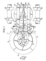
- the magazine plate consists of a support cross 4 attached to a central column 3, a rigid support ring 5, which is rigidly attached to the ends of the support cross struts, and four ring segments ten 6, which form the ring-shaped tool carrier in the assembled state and each have a plurality of tool holders 7 on their outer edge with clamping or snap-in holders for the tool cone.
- Each of the four ring segments 6 can be removed and installed individually from the magazine. In the installed state shown in Fig. 1, locking elements 8 are effective between the support ring 5 and each of the segments which, for. B.
- clamping bolts in the form of common in machine tool clamping bolts, whose hydraulic cylinders are installed in the support ring 5 and are connected via channels 9 with 3 in the column 3 pressure oil channels 10 in connection.
- clamping bolts other fastening elements can also be used for fixing the ring segments to the support ring and also with one another, which can be actuated mechanically, hydraulically, pneumatically or also electrically and ensure a sufficiently dimensionally stable and vibration-free mounting of the ring segments on the support ring or among one another.
- 1 are pivotable bolt 11 for mutual support and additional mounting of two adjacent ring segments indicated by dash-dotted lines.
- the magazine plate is rotated by means of a drive motor (not shown) until the selected tool or an empty position in the change position W is opposite the tool changer 12.
- a drive motor not shown
- the function and mode of operation of the plate magazine corresponds to the usual designs.
- a turntable 15 serves as the transfer device for the individual segments, on which two guide rails 16, 17 are mounted in parallel next to one another and are mutually stiffened by cross struts 18, 19.
- the turntable 15 can be rotated in both directions of rotation by at least 180 ° by means of a drive (not shown).
- the two guide rails 16, 17 are aligned with stationary rail sections 20, 21, which are, for example, fixedly mounted on the support structure 22 of the magazine plate 5, for example on a part of the headstock.
- These guide rail sections 20, 21 extend to below the edge of the magazine plate or the ring segment 6. At its radially inner edge, this ring segment 6 has a downwardly extending ring segment-shaped extension 22 ⁇ , which is shown in broken lines in FIG. 1.
- an opening 23 is centrally provided for the engagement of a locking hook or bolt 24 at the end of a piston rod 25.
- the piston rod 25 is part of a hydraulic pressure cylinder unit 26 which is mounted on the turntable 15 and pressurized oil is supplied via lines, not shown.
- a pair of fixed guide rails 27, 28 and 29, 30 On both sides of the turntable 15 ends a pair of fixed guide rails 27, 28 and 29, 30. These guide rails 27 to 30 are arranged and designed so that they are flush with the two guide rails 16, 17 of the turntable 15 when the latter is wired from its position shown by 90 ° in one direction or the other.
- the piston 25 of the cylinder unit 26 is extended until the hook 24 engages in the recess 23 at its free end and is fixed there by suitable means, for example by a spring clamp .
- the clamping cartridges 8 are pressurized with pressure oil via line 9 and thereby released.
- the now released segment 6 is pulled onto a pallet (not shown in FIG. 1) and brought together with this on the rails 20, 21 to the turntable 15.
- the turntable 15 By subsequently rotating the turntable 15 until it is aligned with the pair of rails 25, 28 or 29, 30 and then extending the piston rod 25, the magazine segment 6, which contains the used tools, is brought into a storage position.
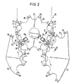
- the embodiment shown in FIG. 2 is a chain magazine in which an endless chain 35 containing the tool holders runs over several chain wheels 36, only one of which is shown.
- the selected tool holders 7 reach the change position by means of a program-controlled drive of at least one of the chain wheels 36.
- the endless chain 35 containing the tool holders 7 is composed of a plurality of chain sections which are detachably connected to one another by specially designed pivot pins.
- Each chain wheel 36 has semicircular cutouts 37 on its outer circumference and semicircular recesses 38 in the intermediate webs delimited by these cutouts 37, in which spring pliers 39 are seated. These spring pliers 39 serve as fixing elements for the joint pins 40 connecting the chain links 41.
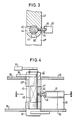
- each hinge pin 40 is flattened on both sides in its central section 42.
- Each chain link 41 has in the region of its one hinge eye 43 a radial cutout 44 transverse to the longitudinal axis of the link, the width of which is slightly larger than the diameter of the bolt shaft in the flattened section 42.
- the cutout 44 diametrically opposite a pin 45 is fixed in the chain link 41 ⁇ (Fig. 3, 4), which is aligned transversely to the longitudinal axis of the link and has a thickened head 46 at its free end.
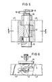
- an anti-rotation device for the hinge pin 40 in the form of a spring-loaded pin 47 is provided at one end of each chain link 41 ⁇ , which with its crowned end resiliently engages in at least one depression in the inner surface of one hinge pin head 48.
- two transverse pins 49, 50 are fastened at a mutual acute angle transversely to the longitudinal axis of the bolt (cf. FIGS. 5 and 6).
- two further chain wheels 51, 52 are located directly next to the chain wheel 36, of which the left chain wheel in FIG. 2 carries a new chain section to be installed in the endless chain and the right chain wheel in FIG. 2 for removing one chain section to be removed from the endless chain.
- a linear motor designed as a pressure medium cylinder 53 is arranged in a stationary manner radially to the chain wheel 36, on the piston rod 54 of which a slide 55 is fastened.
- This linear drive 53 also shown in FIG. 6, acts on the transverse pin 49 fastened to the free end of the respective hinge pin 40 in order to twist the hinge pin 40 about its longitudinal axis.
- Another linear drive 56 of the same type is arranged radially to the sprocket 36 in a fixed position at point N in FIG. 2, on the piston rod 57 of which a slide 58 is also fastened, which engages on the transverse pin 50 of the joint pin 40 and rotates the latter about its longitudinal axis in the opposite direction.
- each chain wheel 36, 51, 52 consists of two uniformly shaped plates or disks, which are arranged at an axial distance corresponding to the chain link height and are fastened on shafts. Between the two plates of the chain wheels 36 and 52, pliers 61 are fastened on bases 60 (see FIG. 4), which encompass the thickened heads 46 of the cross pins 45.
- each sprocket 51, 52 in each plate on the outer circumference has semicircular cutouts 62, 63 and semicircular recesses 64, 65 with spring pliers 66 fixed therein, which correspond to the elements 37 to 39 of the sprocket 36 in terms of mode of operation and shape.
- the hinge pin 40 rotates by a predetermined amount so that the two flat side surfaces of its flattened central shaft section 42 are aligned parallel to the boundary surfaces of the radial cutout, as shown in FIG. 3.
- the pliers 61 attached to the chain wheel 52 grip the thickened head 46 of the projecting pin 45 (FIGS. 3, 4).
- the pliers 61 engaging behind the thickened head 46 hold the incoming chain link 41 ⁇ on the outer circumference of the sprocket 52, the pivot pin 42 simultaneously sliding out of the radial cutout 44 of the chain link 41.
- a certain chain section the length of which corresponds to the center distance of the two chain wheels 70, 71, can be replaced at the same time.
- the construction and function of the two sprockets 70, 71 corresponds to that of the sprocket 36 in FIG. 2.
- Tenbolzen serve two linear drives 53 of the same construction as the linear drive 53 in Fig. 2.
- the chain section 73 detached from the endless chain 35 is taken over by a holder 74 which has cross webs 75, 76 with corresponding mounting brackets and is mounted on a self-propelled carriage or the like can be.
- the transfer and change operations essentially correspond to those of the exemplary embodiment according to FIGS. 2 to 6.
- FIGS. 1 and 2 can be combined with one another in such a way that an endless chain with tool holders is mounted on the outer circumference of the magazine plate, the individual sections of which are then exchanged in a suitable manner in accordance with the embodiment according to FIG. 2.
Landscapes
- Engineering & Computer Science (AREA)
- Mechanical Engineering (AREA)
- Automatic Tool Replacement In Machine Tools (AREA)
Abstract
Gegenstand der Erfindung ist ein Werkzeugmagazin für programmgesteuerte Werkzeugmaschinen, bestehend aus einer Tragkonstruktion, einem die Werkzeugaufnahmen (7) enthaltenden Träger (5, 6, 35) und einem programmgesteuerten elektrischen Antrieb, welcher den Träger zusammen mit den Werkzeugaufnahmen (7) in bestimmte Positionen für den Werkzeugwechsel fährt. Gemäß der Erfindung ist der Werkzeugträger in mehrere austauschbare Segmente (6) unterteilt, die mittels einer Übergabe-Einrichtung (15) vom und zum Magazin transportiert und in dieses ein- und ausgebaut werden können. 
Description
Die Erfindung betrifft ein Werkzeugmagazin der im Oberbegriff des Patentanspruchs 1 angegebenen Gattung.The invention relates to a tool magazine of the type specified in the preamble of claim 1.
Mit der Entwicklung von sog. Bearbeitungszentren und von flexiblen Fertigungssystemen wachsen naturgemäß die Anforderungen an die Werkzeugwechselsysteme, die einen vollautomatischen Ablauf der aus einer Vielzahl von unterschiedlichen Vorgängen bestehenden Werkstückbearbeitung erst ermöglichen. Der vollautomatische Langzeitbetrieb eines programmgesteuerten Bearbeitungszentrums findet seine Grenze u.a. in den maximalen Standzeiten der eingesetzten Werkzeuge. Daneben besteht in der Regel das Problem, daß bestimmte Werkzeuge bei der Bearbeitung eines Werkstücks häufiger und/oder länger eingesetzt werden als andere, so daß sie auch früher verschleißen. Diese Werkzeuge müssen dann im Werkzeugmagazin gegen neue ersetzt werden, was bei herkömmlichen Teller- oder Kettenmagazinen relativ häufige Eingriffe in den Bearbeitungsablauf bedeutet, da das Besetzen des jeweiligen Magazins mit Werkzeugen in der Regel bei stillstehender Maschine manuell vorgenommen werden muß. Besondere Anforderungen an Werkzeugwechselsysteme ergeben sich schließlich bei den in neuerer Zeit konzipierten Mehrspindelautomaten, in denen jeweils mehrere gleichartige Werkstücke gleichzeitig bearbeitet werden. Bei diesen Automaten versorgt in der Regel ein Werkzeugmagazin mindestens zwei Bearbeitungsspindeln jeweils mit gleichen Werkzeugen, die dann auch in einer entsprechend großen Anzahl im Magazin gespeichert sein müssen.With the development of so-called machining centers and flexible manufacturing systems, the demands placed on tool changing systems naturally grow, which make a fully automated process of workpiece machining consisting of a multitude of different processes possible. The fully automatic long-term operation of a program-controlled machining center has its limits, among other things, in the maximum service life of the tools used. In addition, there is usually the problem that certain tools are used more often and / or longer than others when machining a workpiece, so that they also wear out earlier. These tools then have to be replaced with new ones in the tool magazine, which means relatively frequent interventions in the machining process in conventional plate or chain magazines, since the respective magazine is filled with tools usually must be done manually when the machine is at a standstill. Finally, there are special requirements for tool changing systems in the multi-spindle machines designed in more recent times, in which several workpieces of the same type are machined simultaneously. In these machines, a tool magazine generally supplies at least two machining spindles with the same tools, which must then also be stored in the magazine in a correspondingly large number.
Den vorstehend kurz angerissenen Problemen wurde bisher durch eine Vergrößerung der Speicherkapazität der Werkzeugmagazine begegnet. In dieser Richtung sind jedoch Grenzen gesetzt, weil mit einer Vergrößerung des Magazins auch dessen Platzbedarf und Gewicht in mindestens gleichem Maße ansteigen sowie auch die Hilfsaggregate, wie Lagerungen und Antriebe, entsprechend größer ausgelegt werden müssen. Daraus ergeben sich erhebliche Schwierigkeiten hinsichtlich der Positionierung der jeweiligen Magazine an der Werkzeugmaschine sowie der Auslegung und Anordnung der Werkzeugwechsler. Darüber hinaus vergrößern sich mit der Speicherkapazität der Magazine auch die Wechselzeiten insgesamt, weil sich die Transportwege der einzelnen Werkzeuge im Magazin zur definierten Wechselposition statistisch verlängern, was die Bearbeitungsleistung der gesamten Maschine nachteilig beeinflußt.The problems briefly outlined above have so far been countered by increasing the storage capacity of the tool magazines. There are limits in this direction, however, because as the magazine is enlarged, its space requirements and weight increase at least to the same extent, and the auxiliary units, such as bearings and drives, have to be designed accordingly larger. This results in considerable difficulties with regard to the positioning of the respective magazines on the machine tool and the design and arrangement of the tool changer. In addition, the storage times of the magazines also increase the total change times because the transport paths of the individual tools in the magazine to the defined change position are statistically extended, which adversely affects the machining performance of the entire machine.
Aufgabe der Erfindung ist es, ein Werkzeugmagazin für programmgesteuerte Werkzeugmaschinen zu schaffen, dessen Speicherkapazität an die Bearbeitungs- und Einsatzbedingungen angepaßt werden kann und das eine verbesserte Auslastung der Werkzeugmaschine ermöglicht.The object of the invention is to provide a tool magazine for program-controlled machine tools, the storage capacity of which can be adapted to the machining and operating conditions and which enables improved utilization of the machine tool.
Diese Aufgabe wird erfindungsgemäß durch die kennzeichnenden Merkmale des Patentanspruchs 1 gelöst.This object is achieved by the characterizing features of claim 1.
Die Unterteilung des Werkzeugträgers, z.B. des Tellers, der Kette od. dgl. in mehrere Segmente oder Einzelabschnitte und deren auswechselbare Anordnung im Magazin eröffnet eine Vielzahl von vorteilhaften betriebstechnischen Möglichkeiten. So können beispielsweise die bei der Bearbeitung eines einzelnen Werkstücks besonders häufig eingesetzten und hoch beanspruchten Werkzeuge in einem bzw. bestimmten Segmenten zusammengefaßt und durch Austausch dieser Segmente als Ganzes automatisch ersetzt werden, was die Rüstzeiten entsprechend vermindert. Daneben ist es für den Langzeitbetrieb (Geisterschichten) einer in ein flexibles Fertigungssystem integrierten Werkzeugmaschine möglich, die zur Bearbeitung eines Werkstücktyps notwendigen Werkzeuge in einem oder mehreren bestimmten Segmenten und die für weitere Werkstücktypen benötigten Werkzeuge in anderen bestimmten Magazin-Segmenten zusammenzustellen. Entsprechendes gilt auch für Mehrspindelautomaten, bei denen die Werkzeuge für die Einzelspindeln ebenfalls gruppenweise austauschbar im Magazin angeordnet werden können.The subdivision of the tool carrier, e.g. of the plate, the chain or the like. In several segments or individual sections and their interchangeable arrangement in the magazine opens up a variety of advantageous operational options. For example, the tools that are used particularly frequently and are subject to high stress when machining a single workpiece can be combined in one or certain segments and automatically replaced as a whole by exchanging these segments, which reduces the set-up times accordingly. In addition, for long-term operation (ghost shifts) of a machine tool integrated in a flexible manufacturing system, it is possible to compile the tools required for machining a workpiece type in one or more specific segments and the tools required for other workpiece types in other specific magazine segments. The same also applies to multi-spindle automatic machines, in which the tools for the individual spindles can also be arranged interchangeably in the magazine.
Das erfindungsgemäße technische Konzept ist in geeigneter konstruktiver Anpassung bei unterschiedlichen Magazintypen anwendbar. So können bei sog. Tellermagazinen die tellerförmigen Träger aus Einzelsegmenten zusammengebaut sein, wobei jedes Segment mittels einer Halterung im Teller festgelegt und mit Hilfe einer geeigneten Verriegelung gesichert und nach deren Lösen ausgebaut werden kann. Jedes Segment kann eine oder mehrere Aufnahmen für die Werkzeuge bzw. deren Kegel aufweisen. Bei Kettenmagazinen kann die Kette aus lös bar miteinander gekuppelten Einzelgliedern oder auch aus Kettenabschnitten von vorgegebener Länge zusammengesetzt sein. Eine z.B. im rückwärtigen Teil der Kettenumlaufbahn angeordnete Einrichtung löst die vorher ausgewählten Kettenglieder und/oder die Kettenabschnitte aus dem Kettenverband und ersetzt diese automatisch durch zuvor mit neuen Werkstücken bestückte Kettenabschnitte.The technical concept according to the invention can be used in a suitable design adaptation for different magazine types. In the case of so-called plate magazines, the plate-shaped carriers can be assembled from individual segments, each segment being fixed in the plate by means of a holder and secured with the aid of a suitable locking device and being able to be removed after it has been released. Each segment can have one or more receptacles for the tools or their cones. With chain magazines the chain can be released bar coupled individual links or be composed of chain sections of a predetermined length. A device arranged, for example, in the rear part of the chain orbit removes the previously selected chain links and / or the chain sections from the chain assembly and replaces them automatically with chain sections previously equipped with new workpieces.
Einer der wesentlichen Vorteile des erfindungsgemäßen Konzepts liegt noch darin, daß die Magazin-Segmente bzw. -Abschnitte in der Werkstatt vorbereitet und unmittelbar an der Werkzeugmaschine bereitgestellt werden können, so daß sie bei Bedarf entsprechend dem jeweiligen Steuerprogramm automatisch gegen die mit "verbrauchten" Werkzeugen bestückten Magazin-Segmente ausgetauscht werden können. Die Anzahl an notwendigen Eingriffen in den Bearbeitungsablauf der Werkzeugmaschine wird dadurch wesentlich reduziert und somit auch deren Leistung vergrößert. Weiterhin kann auch der Automatisierungsgrad von komplexen Fertigungssystemen auf relativ einfache Weise gesteigert werden, weil die fertig vorbereiteten Magazin-Segmente z.B. auf selbstfahrenden Flurförderern in ihre Bereitstellungen automatisiert gefördert werden können.One of the main advantages of the concept according to the invention is that the magazine segments or sections can be prepared in the workshop and provided directly on the machine tool, so that they can automatically be used against the "used" tools according to the respective control program equipped magazine segments can be exchanged. This significantly reduces the number of necessary interventions in the machining process of the machine tool and thus also increases their performance. Furthermore, the degree of automation of complex manufacturing systems can also be increased in a relatively simple way, because the prepared magazine segments e.g. can be automatically promoted in their deployments on self-driving floor conveyors.
Das erfindungsgemäße Konzept sowie zweckmäßige Weiterbildungen und Ausgestaltungen der Erfindung ergeben sich aus den Unteransprüchen, der Zeichnung und der folgenden Beschreibung von Ausführungsbeispielen. Es zeigen:
- Fig. 1 als erstes Ausführungsbeispiel der Erfindung ein Tellermagazin in schematischer Draufsicht;
- Fig. 2 ein weiteres Ausführungsbeispiel der Erfindung in Form eines Kettenmagazins mit einer Vorrichtung für den Wechsel von Kettenabschnitten in schematischer Draufsicht;
- Fig. 3 einen Schnitt durch ein Kettengelenk in der Schnittebene III-III der Fig. 4;
- Fig. 4 einen Längsschnitt durch ein Kettengelenk in der Schnittebene IV-IV in Fig. 2;
- Fig. 5 einen Längsschnitt durch ein Kettengelenk in der Schnittebene V-V in Fig. 2;
- Fig. 6 eine Draufsicht auf ein Kettengelenk mit dem Druckmittelzylinder zum Verdrehen des Gelenkbolzens;
- Fig. 7 eine weitere Ausführung der Erfindung in schematischer Draufsicht.
- Figure 1 as a first embodiment of the invention, a plate magazine in a schematic plan view.
- Figure 2 shows a further embodiment of the invention in the form of a chain magazine with a device for changing chain sections in a schematic plan view.
- 3 shows a section through a chain link in the sectional plane III-III of FIG. 4.
- Figure 4 is a longitudinal section through a chain link in the section plane IV-IV in Fig. 2.
- 5 shows a longitudinal section through a chain link in the sectional plane VV in FIG. 2;
- 6 shows a plan view of a chain link with the pressure medium cylinder for rotating the link pin;
- Fig. 7 shows a further embodiment of the invention in a schematic plan view.
Bei der Ausführung nach Fig. 1 ist ein Tellermagazin 1 z. B. auf einem nicht dargestellten Spindelstock montiert. Der Magazinteller besteht aus einem an einer zentralen Säule 3 befestigten Tragkreuz 4, aus einem formsteifen Tragring 5, der an den Enden der Tragkreuz-Streben starr befestigt ist, und aus vier Ringsegmen ten 6, die im zusammengebauten Zustand den ringförmigen Werkzeugträger bilden und an ihrem Außenrand jeweils mehrere Werkzeugaufnahmen 7 mit Klemm- oder Rasthalterungen für die Werkzeugkegel aufweisen. Jedes der vier Ringsegmente 6 kann einzeln aus dem Magazin aus- und eingebaut werden. In dem in Fig. 1 dargestellten eingebauten Zustand sind Verriegelungselemente 8 zwischen dem Tragring 5 und jedem der Segmente wirksam, die z. B. in Form von im Werkzeugmaschinenbau geläufigen Klemmbolzen ausgebildet sein können, deren hydraulische Zylinder im Tragring 5 eingebaut sind und über Kanäle 9 mit in der Säule 3 verlegten Druckölkanälen 10 in Verbindung stehen. Statt der Klemmbolzen können auch andere Befestigungselemente zur Fixierung der Ringsegmente am Tragring sowie auch untereinander verwendet werden, die mechanisch, hydraulisch, pneumatisch oder auch elektrisch betätigbar sind und eine ausreichend formsteife und schwingungsfreie Halterung der Ringsegmente am Tragring bzw. untereinander gewährleisten. In Fig. 1 sind schwenkbare Riegel 11 zur gegenseitigen Abstützung und zusätzlichen Halterung von jeweils zwei benachbarten Ringsegmenten strichpunktiert angedeutet.1 is a plate magazine 1 z. B. mounted on a headstock, not shown. The magazine plate consists of a support cross 4 attached to a central column 3, a rigid support ring 5, which is rigidly attached to the ends of the support cross struts, and four ring segments ten 6, which form the ring-shaped tool carrier in the assembled state and each have a plurality of tool holders 7 on their outer edge with clamping or snap-in holders for the tool cone. Each of the four ring segments 6 can be removed and installed individually from the magazine. In the installed state shown in Fig. 1,
Zum Wechseln der Werkzeuge wird der Magazinteller mittels eines nicht dargestellten Antriebsmotors so weit verdreht, bis das ausgewählte Werkzeug bzw. eine Leerstelle in der Wechselposition W dem Werkzeugwechsler 12 gegenüberliegt. Insoweit entspricht die Funktion und Arbeitsweise des Tellermagazins den üblichen Ausführungen.To change the tools, the magazine plate is rotated by means of a drive motor (not shown) until the selected tool or an empty position in the change position W is opposite the tool changer 12. In this respect, the function and mode of operation of the plate magazine corresponds to the usual designs.
Als Übergabevorrichtung für die einzelnen Segmente dient bei der dargestellten Ausführung ein Drehtisch 15, auf dem zwei Führungsschienen 16, 17 parallel nebeneinander montiert und gegenseitig durch Querstreben 18, 19 versteift sind. Der Drehtisch 15 ist in beiden Drehrichtungen um mindestens 180° mittels eines - nicht dargestellten - Antriebes verdrehbar. Die beiden Führungsschienen 16, 17 fluchten mit ortsfesten Schienenabschnitten 20, 21, die z.B. auf der Tragkonstruktion 22 des Magazintellers 5, z.B. auf einem Teil des Spindelstocks fest montiert sind. Diese Führungsschienen-Abschnitte 20, 21 erstrecken sich bis unter den Rand des Magazintellers bzw. des Ringsegments 6. An seinem radial inneren Rand weist dieses Ringsegment 6 einen sich nach unten erstreckenden ringsegmentförmigen Ansatz 22ʹ auf, der in Fig. 1 gestrichelt dargestellt ist. In diesem Ringansatz 22ʹ ist zentral eine Öffnung 23 für den Eingriff eines Rasthakens oder Riegels 24 am Ende einer Kolbenstange 25 vorgesehen. Die Kolbenstange 25 ist Teil einer hydraulischen Druckzylindereinheit 26, die auf dem Drehtisch 15 montiert ist und über nicht dargestellte Leitungen mit Drucköl beaufschlagt wird.In the embodiment shown, a turntable 15 serves as the transfer device for the individual segments, on which two
Zu beiden Seiten des Drehtisches 15 endet je ein Paar von ortsfest montierten Führungsschienen 27, 28 bzw. 29, 30. Diese Führungsschienen 27 bis 30 sind so angeordnet und ausgebildet, daß sie mit den beiden Führungsschienen 16, 17 des Drehtisches 15 fluchten, wenn dieser aus seiner dargestellten Position um 90° in der einen oder anderen Richtung verdraht wird.On both sides of the turntable 15 ends a pair of fixed
Zum Ausbau eines Ringsegments 6 aus der in Fig. 1 dargestellten Position wird der Kolben 25 der Zylindereinheit 26 so weit ausgefahren, bis der Haken 24 an seinem freien Ende in die Ausnehmung 23 eingreift und dort durch geeignete Mittel, z.B. durch eine Federklemmung, fixiert wird. Gleichzeitig werden die Klemmpatronen 8 mit Drucköl über die Leitung 9 beaufschlagt und dadurch gelöst. Durch anschließendes Einfahren des Kolbens 25 wird das nunmehr freigegebene Segment 6 auf eine - in Fig. 1 nicht dargestellte - Palette gezogen und zusammen mit dieser auf den Schienen 20, 21 bis auf den Drehtisch 15 gebracht. Durch anschließendes Verdrehen des Drehtisches 15 bis zur Flucht mit dem Schienenpaar 25, 28 bzw. 29, 30 und anschließendes Ausfahren der Kolbenstange 25 wird das - die verbrauchten Werkzeuge enthaltende - Magazin-Segment 6 in eine Abstellposition gebracht. Nach Einfahren des Zylinders 25 und einer Verdrehung um 180° kann ein auf einer Palette angeordnetes neues Segment 6 erfaßt und vom Kolben 25 auf die Schienen 16, 17 des Drehtisches 15 gebracht werden. Nach einer Rückdrehung des Drehtisches um 90° befinden sich seine Führungsschienen 16, 17 wieder in Flucht mit den Schienenabschnitten 20, 21, so daß das neue Segment in seine Betriebslage gebracht und durch Betätigen der Klemmbolzen 8 am Tragring 5 befestigt werden kann. Nach Lösen des Hakens 24 und Einziehen der Kolbenstange 25 ist der Wechselvorgang abgeschlossen.To remove a ring segment 6 from the position shown in FIG. 1, the piston 25 of the
Bei der in Fig. 2 dargestellten Ausführung handelt es sich um ein Kettenmagazin, bei dem eine die Werkzeugaufnahmen enthaltende Endloskette 35 über mehrere Kettenräder 36 läuft, von denen nur eines dargestellt ist. Durch programmgesteuerten Antrieb mindestens eines der Kettenräder 36 gelangen die ausgewählten Werkzeugaufnahmen 7 in die Wechselposition. Die die Werkzeugaufnahmen 7 enthaltende Endloskette 35 ist aus mehreren Kettenabschnitten zusammengesetzt, die durch speziell ausgebildete Gelenkbolzen lösbar miteinander verbunden sind. Jedes Kettenrad 36 weist an seinem Außenumfang halbkreisförmige Ausschnitte 37 und in den von diesen Ausschnitten 37 begrenzten Zwischenstegen halbrunde Ausnehmungen 38 auf, in denen Federzangen 39 sitzen. Diese Federzangen 39 dienen als Fixierelemente für die die Kettenglieder 41 verbindenden Gelenkbolzen 40.The embodiment shown in FIG. 2 is a chain magazine in which an
Wie aus den Fig. 3 bis 6 ersichtlich, ist jeder Gelenkbolzen 40 in seinem mittleren Abschnitt 42 beidseitig abgeflacht. Jedes Kettenglied 41 weist im Bereich seines einen Gelenkauges 43 einen radialen Ausschnitt 44 quer zur Gliedlängsachse auf, dessen Breite geringfügig größer als der Durchmesser des Bolzenschaftes im abgeflachten Abschnitt 42 ist. Dem Ausschnitt 44 diametral gegenüberliegend ist im Kettenglied 41ʹ (Fig. 3, 4) ein Zapfen 45 befestigt, der quer zur Gliedlängsachse ausgerichtet ist und an seinem freien Ende einen verdickten Kopf 46 aufweist.As can be seen from FIGS. 3 to 6, each
Wie aus Fig. 5 ersichtlich, ist eine Verdrehsicherung für den Gelenkbolzen 40 in Form eines federbelasteten Stiftes 47 an einem Ende jedes Kettengliedes 41ʺ vorgesehen, der mit seinem balligen Ende in mindestens eine Einsenkung in der Innenfläche des einen Gelenkbolzenkopfes 48 federnd eingreift. Am anderen Ende des Gelenkbolzens 40 sind zwei Querstifte 49, 50 unter einem gegenseitigen spitzen Winkel quer zur Bolzenlängsachse befestigt (vgl. Fig. 5 und 6).As can be seen from FIG. 5, an anti-rotation device for the
Wie aus Fig. 2 ersichtlich, befinden sich unmittelbar neben dem Kettenrad 36 zwei weitere Kettenräder 51, 52, von denen das in Fig. 2 linke Kettenrad einen neuen und in die Endloskette einzubauenden Kettenabschnitt trägt und das in Fig. 2 rechte Kettenrad zum Abführen eines aus der Endloskette auszubauenden Kettenabschnittes dient. An der Stelle M ist ein als Druckmittelzylinder 53 ausgebildeter Linearmotor radial zum Kettenrad 36 ortsfest angeordnet, an dessen Kolbenstange 54 ein Schieber 55 befestigt ist. Dieser auch in Fig. 6 dargestellte Linearantrieb 53 wirkt auf den am freien Ende des jeweiligen Gelenkbolzens 40 befestigten Querstift 49, um den Gelenkbolzen 40 um seine Längsachse zu verdrehen. Ein weiterer gleichartiger Linearantrieb 56 ist radial zum Kettenrad 36 ortsfest an der Stelle N in Fig. 2 angeordnet, an dessen Kolbenstange 57 ebenfalls ein Schieber 58 befestigt ist, welcher an dem Querstift 50 des Gelenkbolzens 40 angreift und letzteren um seine Längsachse im Gegensinn verdreht.As can be seen from FIG. 2, two
Wie aus Fig. 4 ersichtlich, besteht jedes Kettenrad 36, 51, 52 aus zwei gleichgeformten Platten bzw. Scheiben, die in einem der Kettengliedhöhe entsprechenden axialen Abstand zueinander angeordnet und auf Wellen befestigt sind. Zwischen den beiden Platten der Kettenräder 36 und 52 sind auf Sockeln 60 Zangen 61 befestigt (vgl. Fig. 4), welche die verdickten Köpfe 46 der Querzapfen 45 umgreifen. Darüber hinaus weist jedes Kettenrad 51, 52 in jeder Platte am Außenumfang halbkreisförmige Ausschnitte 62, 63 sowie halbrunde Ausnehmungen 64, 65 mit darin festgelegten Federzangen 66 auf, welche den Elementen 37 bis 39 des Kettenrades 36 hinsichtlich Wirkungsweise und Formgebung entsprechen.As can be seen from FIG. 4, each
Die vorstehend beschriebene und in Fig. 2 bis 6 dargestellte Ausführung arbeitet wie folgt:The embodiment described above and shown in FIGS. 2 to 6 works as follows:
Wenn ein aus einem oder mehreren Kettengliedern bestehender Kettenabschnitt des Kettenmagazins mit den entsprechenden Werkzeugen ausgewechselt werden soll, wird die Endloskette in eine in der rechten Seite der Fig. 2 dargestellte und mit M bezeichnete Position gefahren, in welcher der den auszuwechselnden Kettenabschnitt mit der verbleibenden Kette verbindende Gelenkbolzen dem Linearmotor 53 genau gegenübersteht. Durch Betätigen dieses Linearmotors 53 und Ausfahren dessen Kolbens 54 drückt der an dem freien Ende des Kolbens 54 quer befestigte Schieber 55 den am Kopfende befestigten Querstift 49 aus der in Fig. 6 in Vollinien dargestellten Schrägstellung in die strichpunktiert dargestellte Parallelstellung. Dabei verdreht sich der Gelenkbolzen 40 um einen vorgegebenen Betrag, so daß die beiden ebenen Seitenflächen seines abgeflachten mittleren Schaftabschnittes 42 parallel zu den Begrenzungsflächen des radialen Ausschnittes ausgerichtet sind, wie dies in Fig. 3 dargestellt ist. Gleichzeitig ergreift die am Kettenrad 52 befestigte Zange 61 den verdickten Kopf 46 des vorstehenden Zapfens 45 (Fig. 3, 4). Durch eine synchrone Verdrehung der beiden Kettenräder 36 und 52 hält die den verdickten Kopf 46 hintergreifende Zange 61 das ankommende Kettenglied 41ʹ am Außenumfang des Kettenrades 52, wobei gleichzeitig der Gelenkbolzen 42 aus dem radialen Ausschnitt 44 des Kettengliedes 41 herausgleitet. Der Bolzen 42 und damit auch das Ende der verbleibenden Endloskette wird durch die teilweise umgreifende Federzange 39 in der halbrunden Ausnehmung 38 des Kettenrades 36 festgehalten, so daß der Endabschnitt der verbleibenden Endloskette am Kettenrad 36 nach wie vor sicher geführt wird. Der mit dem Kettenglied 41ʹ gemäß Fig. 3 beginnende auszuwechselnde Kettenabschnitt gelangt durch eine synchrone Weiterdrehung der beiden Kettenräder 36 und 52 auf das Kettenrad 52 und wird von dieser übernommen. Das Lösen des letzten Kettengliedes dieses auszuwechselnden Kettenabschnittes erfolgt in gleicher Weise durch Anhalten der Kette in der Position M und Verdrehen des jeweiligen Gelenkbolzens durch Betätigen des Linearantriebes 53, 54, 55.If a chain section of the chain magazine consisting of one or more chain links is to be replaced with the appropriate tools, the endless chain is moved into a position shown in the right-hand side of FIG. 2 and designated by M, in which the chain section to be exchanged with the remaining chain connecting hinge pin faces the
Die Zuführung ebenso wie das Anschließen eines neuen einzuwechselnden Kettenabschnittes erfolgt mit Hilfe des in Fig. 2 linken Kettenrades 51, auf dessen Umfang der einzuwechselnde Kettenabschnitt durch die die Kettenbolzen 40 umgreifenden Federzangen 65 gehalten wird. Wenn das letzte Glied der Endloskette und synchron das erste Glied des einzuwechselnden Kettenabschnittes die Position N erreichen, erfolgt ein automatisches Eingreifen des in der Stellung nach Fig. 3 befindlichen Gelenkbolzens in den radialen Ausschnitt 44 des ersten Gliedes des ankommenden Kettenabschnitts. Durch Betätigen des Linearmotors 56 und Verschieben seines Kolbens 57 und seines Schiebers 58 drückt dieser Schieber 58 gegen den zweiten Querstift 50 am freien Ende des Gelenkbolzens 40 (Fig. 5), der dadurch in die in Fig. 6 mit Vollinien dargestellte parallele Lage gelangt und den Gelenkbolzen 40 so weit verdreht, daß sein abgeflachter Schaftabschnitt 42 nicht mehr durch die radiale Ausnehmung 44 des Kettengliedes hindurchtreten kann. Damit ist der einzuwechselnde Kettenabschnitt an das letzte Glied der Endloskette angeschlossen. Ein entsprechender Vorgang wiederholt sich zwischen dem letzten Glied des einzuwechselnden Kettenabschnittes und dem ersten Glied der Endloskette.The feeding as well as the connection of a new chain section to be replaced takes place with the help of the
Bei der in Fig. 7 dargestellten Ausführung kann ein bestimmter Kettenabschnitt, dessen Länge dem Achsabstand der beiden Kettenräder 70, 71 entspricht, gleichzeitig ausgewechselt werden. Die Konstruktion und Funktion der beiden Kettenräder 70, 71 entspricht der des Kettenrades 36 in Fig. 2. Zum gleichzeitigen Lösen der in den Positionen M und N befindlichen Ket tenbolzen dienen zwei Linearantriebe 53 gleicher Konstruktion wie der Linearantrieb 53 in Fig. 2. Der aus der Endloskette 35 gelöste Kettenabschnitt 73 wird von einer Halterung 74 übernommen, die Qurstege 75, 76 mit entsprechenden Aufnahmehalterungen aufweist und auf einem selbstfahrenden Wagen od. dgl. montiert sein kann. Die Übergabe- und Wechseloperationen entsprechen im wesentlichen denen des Ausführungsbeispiels nach Fig. 2 bis 6.In the embodiment shown in FIG. 7, a certain chain section, the length of which corresponds to the center distance of the two chain wheels 70, 71, can be replaced at the same time. The construction and function of the two sprockets 70, 71 corresponds to that of the
Die Erfindung ist nicht auf die dargestellten Ausführungsbeispiele beschränkt. So können beispielsweise die in den Fig. 1 und 2 dargestellten Maßnahmen in der Weise miteinander kombiniert werden, daß am Außenumfang des Magazintellers eine Endloskette mit Werkzeugaufnahmen montiert wird, deren einzelne Abschnitte dann in einer geeigneten Weise entsprechend der Ausführung nach Fig. 2 ausgewechselt werden.The invention is not restricted to the exemplary embodiments shown. For example, the measures shown in FIGS. 1 and 2 can be combined with one another in such a way that an endless chain with tool holders is mounted on the outer circumference of the magazine plate, the individual sections of which are then exchanged in a suitable manner in accordance with the embodiment according to FIG. 2.
Claims (11)
dadurch gekennzeichnet,
daß der die Werkzeugaufnahmen (7) enthaltende Träger (5, 6; 35) in mehrere austauschbare Segmente unterteilt ist und
daß eine Übergabeeinrichtung (15; 53, 56, 61) für den Ein- und Ausbau der Segmente in und aus dem Träger (5, 6; 35) vorgesehen ist.1. Tool magazine for program-controlled machine tools, consisting of a supporting structure, a carrier containing the tool holders and a program-controlled electrical drive for the movements of the supporting structure with the tool holders in predetermined changing positions,
characterized,
that the carrier (5, 6; 35) containing the tool holders (7) is divided into several interchangeable segments and
that a transfer device (15; 53, 56, 61) is provided for installing and removing the segments in and out of the carrier (5, 6; 35).
dadurch gekennzeichnet,
daß die Werkzeugaufnahmen (7) in Ringsegmenten (6) ausgebildet sind, welche an einem Tragring (5) des drehangetriebenen Tellers lösbar befestigt sind.2. Tool magazine according to claim 1, wherein the tool carrier is a rotary driven plate,
characterized,
that the tool holders (7) are formed in ring segments (6) which are releasably attached to a support ring (5) of the rotary plate.
dadurch gekennzeichnet,
daß die Übergabevorrichtung (15) verdrehbar ausgebildet ist und Führungen (16, 17) für die auszutauschenden Ringsegmente (6) aufweist.3. Tool magazine according to claim 2,
characterized,
that the transfer device (15) is rotatable and has guides (16, 17) for the ring segments (6) to be exchanged.
dadurch gekennzeichnet,
daß die Ringsegmente (6) mittels Klemmpatronen (8) od. dgl. am Tragring (5) fixierbar sind.4. Tool magazine according to one of claims 1 to 3,
characterized,
that the ring segments (6) can be fixed by means of clamping cartridges (8) or the like on the support ring (5).
dadurch gekennzeichnet,
daß die Endloskette (35) aus mehreren lösbar aneinander gekoppelten Abschnitten besteht und daß mindestens eine Einrichtung zum automatischen An- und Abkuppeln vorgewählter Kettenabschnitte vorgesehen ist.5. Tool magazine according to claim 1, wherein the carrier is an endless chain,
characterized,
that the endless chain (35) consists of several detachably coupled sections and that at least one device for automatically coupling and uncoupling preselected chain sections is provided.
dadurch gekennzeichnet,
daß in den Gelenkaugen (43) der Kettenglieder (41ʹ) radiale Ausschnitte (44) ausgebildet sind und daß die Gelenkbolzen (40) durch die Kuppelvorrichtung (53, 56) verdrehbar in den Gelenkaugen (43) aufgenommen sind und abgeflachte Schäfte (42) aufweisen.6. Tool magazine according to claim 5,
characterized,
that in the hinge eyes (43) of the chain links (41ʹ) radial cutouts (44) are formed and that the hinge pins (40) are rotatably received by the coupling device (53, 56) in the hinge eyes (43) and have flattened shafts (42) .
dadurch gekennzeichnet,
daß im Bereich eines Magazin-Kettenrades (36) weitere Kettenräder (51, 52) mit Fixiergliedern (65, 66) zum Zu- bzw. Abführen der aus der Endloskette gelösten Kettenabschnitte angeordnet sind.7. Tool magazine according to claim 5 or 6,
characterized,
that in the area of a magazine sprocket (36) further sprockets (51, 52) with fixing members (65, 66) for Supply or discharge of the chain sections detached from the endless chain are arranged.
dadurch gekennzeichnet,
daß die Kuppelvorrichtung dem Magazin-Kettenrad (36) zugeordnete Linearantriebe (53, 56) enthält, deren Stößel (54, 57) auf Querstifte (49, 50) an den Gelenkbolzen einwirken und diese in den Gelenkaugen (43) der Kettenglieder (41ʹ, 42ʹ) verdrehen.8. Tool magazine according to claim 7,
characterized,
that the coupling device contains the magazine chain wheel (36) associated linear drives (53, 56), the plunger (54, 57) of which act on transverse pins (49, 50) on the hinge pin and these in the hinge eyes (43) of the chain links (41ʹ, 42ʹ).
dadurch gekennzeichnet,
daß am Außenumfang der Kettenräder in halbrunden Ausschnitten (39, 64, 65) Federzangen (39; 65) ausgebildet sind, in welche die Gelenkbolzen (40) einschnappen.9. Tool magazine according to claim 6,
characterized,
that on the outer circumference of the sprockets in semicircular cutouts (39, 64, 65) spring pliers (39; 65) are formed, into which the hinge pins (40) snap.
dadurch gekennzeichnet,
daß an mindestens einem Endteil jedes Kettengliedes (41ʹ) ein Querzapfen (45, 46) diametral gegenüberliegend zum radialen Ausschnitt (44) angeordnet ist und daß an einem neben dem Magazin-Kettenrad (36) befindlichen Ablauf-Kettenrad (52) Zangen (61) montiert sind, welche die verdickten Bolzen der Querstifte (45) umgreifen.10. Tool magazine according to one of claims 5 to 9,
characterized,
that on at least one end part of each chain link (41ʹ) a transverse pin (45, 46) is arranged diametrically opposite the radial cutout (44) and that on a drain sprocket (52) located next to the magazine sprocket (36) pliers (61) are mounted, which encompass the thickened bolts of the cross pins (45).
dadurch gekennzeichnet,
daß eine Vorrichtung (74) zum gleichzeitigen Ausbau eines Kettenabschnittes vorgesehen ist.11. Tool magazine according to claim 1 or 5,
characterized,
that a device (74) is provided for the simultaneous removal of a chain section.
Applications Claiming Priority (2)
| Application Number | Priority Date | Filing Date | Title |
|---|---|---|---|
| DE3613206 | 1986-04-18 | ||
| DE19863613206 DE3613206A1 (en) | 1986-04-18 | 1986-04-18 | TOOL MAGAZINE |
Publications (3)
| Publication Number | Publication Date |
|---|---|
| EP0243537A2 true EP0243537A2 (en) | 1987-11-04 |
| EP0243537A3 EP0243537A3 (en) | 1989-03-15 |
| EP0243537B1 EP0243537B1 (en) | 1991-07-17 |
Family
ID=6299033
Family Applications (1)
| Application Number | Title | Priority Date | Filing Date |
|---|---|---|---|
| EP86116544A Expired - Lifetime EP0243537B1 (en) | 1986-04-18 | 1986-11-28 | Tool magazine |
Country Status (4)
| Country | Link |
|---|---|
| US (1) | US4835837A (en) |
| EP (1) | EP0243537B1 (en) |
| JP (1) | JPS62251039A (en) |
| DE (2) | DE3613206A1 (en) |
Cited By (1)
| Publication number | Priority date | Publication date | Assignee | Title |
|---|---|---|---|---|
| DE4304361A1 (en) * | 1993-02-13 | 1994-08-18 | Chiron Werke Gmbh | Tool changing method and machine tool for performing the method |
Families Citing this family (11)
| Publication number | Priority date | Publication date | Assignee | Title |
|---|---|---|---|---|
| DE3715874C1 (en) * | 1987-05-01 | 1988-10-13 | Werner & Kolb Werkzeugmasch | Device for changing tools of a numerically controlled machining center |
| DE3817256A1 (en) * | 1988-05-20 | 1989-11-23 | Werner & Kolb Werkzeugmasch | Method and device for the rapid interchanging of tools in a numerically controlled machine tool |
| US5424621A (en) * | 1993-08-03 | 1995-06-13 | Industrial Technology Research Institute | Parallel conjugate cam type tool magazine mechanism |
| US5672145A (en) * | 1996-06-27 | 1997-09-30 | Bridgeport Machines Inc. | Tool carousel |
| DE19708096A1 (en) * | 1997-02-28 | 1998-09-03 | Hueller Hille Gmbh | Machining center |
| DE69729850T2 (en) * | 1997-03-11 | 2005-08-25 | Posalux S.A. | Machine tool with a tool magazine with increased capacity and tool magazine for equipping a machine tool |
| GB2375061B (en) * | 1997-09-12 | 2003-01-29 | Bridgeport Machines Ltd | Drive mechanism for a tool carousel wheel |
| EP1122008A1 (en) * | 2000-02-02 | 2001-08-08 | Maschinenfabrik Berthold Hermle Aktiengesellschaft | Machine tool with a rotary magazine for holding tools |
| EP1122023A1 (en) * | 2000-02-02 | 2001-08-08 | Maschinenfabrik Berthold Hermle Aktiengesellschaft | Machine tool for turning and milling |
| DE10144605A1 (en) * | 2001-09-11 | 2003-03-27 | Heller Geb Gmbh Maschf | Method for loading tool magazines of a device for machining workpieces |
| US20070152814A1 (en) * | 2005-12-29 | 2007-07-05 | Arinc Inc. | Systems and methods for autonomous data acquisition, sensor integration and information transmission in a lightweight device |
Family Cites Families (9)
| Publication number | Priority date | Publication date | Assignee | Title |
|---|---|---|---|---|
| US3715801A (en) * | 1969-03-04 | 1973-02-13 | Y Sato | Tool changer for machine tool |
| JPS5633215B2 (en) * | 1973-07-28 | 1981-08-01 | ||
| US4306350A (en) * | 1980-05-12 | 1981-12-22 | Kearney & Trecker Corporation | Automatic tool changer and tool storage arrangement for machine tool |
| DE3316999A1 (en) * | 1982-08-05 | 1984-02-09 | VEB Werkzeugmaschinenkombinat "Fritz Heckert" Karl-Marx-Stadt, DDR 9030 Karl-Marx-Stadt | DEVICE FOR STORING TOOLS OF AN AUTOMATIC MACHINE TOOL |
| US4590662A (en) * | 1982-09-03 | 1986-05-27 | Makino Milling Machine Co., Ltd. | Tool changing machine of machine tool |
| US4577389A (en) * | 1983-04-19 | 1986-03-25 | Textron, Inc. | Automatic tool changer |
| FR2556262B1 (en) * | 1983-12-09 | 1987-02-20 | Ressencourt Hubert | THE PRESENT INVENTION CONCERNS A CENTER FOR FORMING SHEET MATERIALS WITH NUMERICAL CONTROL |
| HU190754B (en) * | 1984-02-14 | 1986-11-28 | Tajnafoel,Jozsef,Hu | Multiple-spindle machining centre |
| DD232858A1 (en) * | 1984-12-27 | 1986-02-12 | Mikromat Dresden Betrieb | DEVICE FOR STORING TOOLS ON TOOLING MACHINES |
-
1986
- 1986-04-18 DE DE19863613206 patent/DE3613206A1/en not_active Ceased
- 1986-11-28 DE DE8686116544T patent/DE3680327D1/en not_active Expired - Fee Related
- 1986-11-28 EP EP86116544A patent/EP0243537B1/en not_active Expired - Lifetime
-
1987
- 1987-01-26 JP JP62015887A patent/JPS62251039A/en active Pending
- 1987-03-27 US US07/031,532 patent/US4835837A/en not_active Expired - Fee Related
Cited By (2)
| Publication number | Priority date | Publication date | Assignee | Title |
|---|---|---|---|---|
| DE4304361A1 (en) * | 1993-02-13 | 1994-08-18 | Chiron Werke Gmbh | Tool changing method and machine tool for performing the method |
| US5474514A (en) * | 1993-02-13 | 1995-12-12 | Chiron-Werke Gmbh & Co. Kg | Method and machine tool for changing tools |
Also Published As
| Publication number | Publication date |
|---|---|
| DE3613206A1 (en) | 1987-10-22 |
| EP0243537B1 (en) | 1991-07-17 |
| JPS62251039A (en) | 1987-10-31 |
| DE3680327D1 (en) | 1991-08-22 |
| EP0243537A3 (en) | 1989-03-15 |
| US4835837A (en) | 1989-06-06 |
Similar Documents
| Publication | Publication Date | Title |
|---|---|---|
| DE3818001C3 (en) | Punching machine with interchangeable and replaceable punching tool and with a workpiece feed | |
| DE69918246T2 (en) | Portable lathes | |
| DE3049495C2 (en) | ||
| DE3902470C2 (en) | ||
| EP0243537B1 (en) | Tool magazine | |
| EP2567783B1 (en) | Grinding machine | |
| EP1179415A2 (en) | Longitudinal machine for the working of corrugated paperboard | |
| DE2325629A1 (en) | TOOL STORAGE MAGAZINE | |
| DE2338617A1 (en) | WELDING MACHINE WITH A COLUMN that can be dismantled | |
| DE2230144A1 (en) | TOOL SUPPORT WITH PLATFORM MOVABLE CHISEL PUSHER WITH A TOOL CHANGER ASSIGNED TO THE CHISEL PUSH | |
| DE3327512C2 (en) | ||
| DE2303198B2 (en) | Device for the automatic, simultaneous and continuous welding of several motor vehicle wheels or similar workpieces | |
| EP0290469B1 (en) | Device for automatic machining of differently-shaped parts | |
| DE1777294A1 (en) | Machine tool | |
| DE3504769A1 (en) | SELF-CENTERING QUICK-CHANGE CUTTING TOOL INSTALLATION | |
| DE3501113C2 (en) | ||
| DE4031997C2 (en) | ||
| DE3439324A1 (en) | MACHINE TOOL FOR DIFFERENT MACHINING PROCESSES | |
| EP3682990B1 (en) | Safety device | |
| DE19700496A1 (en) | Ceramic roller moulding machine | |
| EP0137117B1 (en) | Tool-changing unit having a presentation device for tool-heads | |
| DE202010016228U1 (en) | Device for automatic tool change | |
| DE3316999A1 (en) | DEVICE FOR STORING TOOLS OF AN AUTOMATIC MACHINE TOOL | |
| DE102016013333B4 (en) | Tool changing device for a machine tool, in particular a machine tool for machining a workpiece | |
| EP0129859B1 (en) | Machine tool, in particular a turret cutting press |
Legal Events
| Date | Code | Title | Description |
|---|---|---|---|
| PUAI | Public reference made under article 153(3) epc to a published international application that has entered the european phase |
Free format text: ORIGINAL CODE: 0009012 |
|
| AK | Designated contracting states |
Kind code of ref document: A2 Designated state(s): CH DE FR GB IT LI |
|
| PUAL | Search report despatched |
Free format text: ORIGINAL CODE: 0009013 |
|
| AK | Designated contracting states |
Kind code of ref document: A3 Designated state(s): CH DE FR GB IT LI |
|
| 17P | Request for examination filed |
Effective date: 19890329 |
|
| 17Q | First examination report despatched |
Effective date: 19900510 |
|
| GRAA | (expected) grant |
Free format text: ORIGINAL CODE: 0009210 |
|
| AK | Designated contracting states |
Kind code of ref document: B1 Designated state(s): CH DE FR GB IT LI |
|
| ITF | It: translation for a ep patent filed | ||
| ET | Fr: translation filed | ||
| GBT | Gb: translation of ep patent filed (gb section 77(6)(a)/1977) | ||
| REF | Corresponds to: |
Ref document number: 3680327 Country of ref document: DE Date of ref document: 19910822 |
|
| PGFP | Annual fee paid to national office [announced via postgrant information from national office to epo] |
Ref country code: FR Payment date: 19910826 Year of fee payment: 6 |
|
| PGFP | Annual fee paid to national office [announced via postgrant information from national office to epo] |
Ref country code: CH Payment date: 19910930 Year of fee payment: 6 |
|
| PGFP | Annual fee paid to national office [announced via postgrant information from national office to epo] |
Ref country code: GB Payment date: 19911114 Year of fee payment: 6 |
|
| PGFP | Annual fee paid to national office [announced via postgrant information from national office to epo] |
Ref country code: DE Payment date: 19920120 Year of fee payment: 6 |
|
| PLBE | No opposition filed within time limit |
Free format text: ORIGINAL CODE: 0009261 |
|
| STAA | Information on the status of an ep patent application or granted ep patent |
Free format text: STATUS: NO OPPOSITION FILED WITHIN TIME LIMIT |
|
| 26N | No opposition filed | ||
| PG25 | Lapsed in a contracting state [announced via postgrant information from national office to epo] |
Ref country code: GB Effective date: 19921128 |
|
| PG25 | Lapsed in a contracting state [announced via postgrant information from national office to epo] |
Ref country code: LI Effective date: 19921130 Ref country code: CH Effective date: 19921130 |
|
| GBPC | Gb: european patent ceased through non-payment of renewal fee |
Effective date: 19921128 |
|
| PG25 | Lapsed in a contracting state [announced via postgrant information from national office to epo] |
Ref country code: FR Effective date: 19930730 |
|
| REG | Reference to a national code |
Ref country code: CH Ref legal event code: PL |
|
| PG25 | Lapsed in a contracting state [announced via postgrant information from national office to epo] |
Ref country code: DE Effective date: 19930803 |
|
| REG | Reference to a national code |
Ref country code: FR Ref legal event code: ST |
|
| PG25 | Lapsed in a contracting state [announced via postgrant information from national office to epo] |
Ref country code: IT Free format text: LAPSE BECAUSE OF NON-PAYMENT OF DUE FEES;WARNING: LAPSES OF ITALIAN PATENTS WITH EFFECTIVE DATE BEFORE 2007 MAY HAVE OCCURRED AT ANY TIME BEFORE 2007. THE CORRECT EFFECTIVE DATE MAY BE DIFFERENT FROM THE ONE RECORDED. Effective date: 20051128 |