EP0243481B1 - Messkopf für die messung der porosität einer sich bewegenden bahn - Google Patents
Messkopf für die messung der porosität einer sich bewegenden bahn Download PDFInfo
- Publication number
- EP0243481B1 EP0243481B1 EP86906807A EP86906807A EP0243481B1 EP 0243481 B1 EP0243481 B1 EP 0243481B1 EP 86906807 A EP86906807 A EP 86906807A EP 86906807 A EP86906807 A EP 86906807A EP 0243481 B1 EP0243481 B1 EP 0243481B1
- Authority
- EP
- European Patent Office
- Prior art keywords
- measuring
- measurement
- plate
- head according
- measuring head
- Prior art date
- Legal status (The legal status is an assumption and is not a legal conclusion. Google has not performed a legal analysis and makes no representation as to the accuracy of the status listed.)
- Expired - Lifetime
Links
- 238000005259 measurement Methods 0.000 title abstract description 28
- 238000007664 blowing Methods 0.000 claims abstract description 24
- 239000011148 porous material Substances 0.000 claims abstract description 6
- 238000007789 sealing Methods 0.000 claims description 6
- 238000006073 displacement reaction Methods 0.000 claims 1
- 238000004140 cleaning Methods 0.000 abstract 1
- 238000000605 extraction Methods 0.000 abstract 1
- 238000009434 installation Methods 0.000 abstract 1
- 230000002000 scavenging effect Effects 0.000 abstract 1
- 239000002245 particle Substances 0.000 description 3
- 238000011161 development Methods 0.000 description 2
- 239000000428 dust Substances 0.000 description 2
- 239000004744 fabric Substances 0.000 description 2
- 239000000835 fiber Substances 0.000 description 2
- 238000004519 manufacturing process Methods 0.000 description 2
- 239000000463 material Substances 0.000 description 2
- 238000000034 method Methods 0.000 description 2
- 238000012544 monitoring process Methods 0.000 description 2
- 238000010926 purge Methods 0.000 description 2
- 230000015572 biosynthetic process Effects 0.000 description 1
- 230000001276 controlling effect Effects 0.000 description 1
- 238000013461 design Methods 0.000 description 1
- 230000001105 regulatory effect Effects 0.000 description 1
Images

Classifications
-
- G—PHYSICS
- G01—MEASURING; TESTING
- G01N—INVESTIGATING OR ANALYSING MATERIALS BY DETERMINING THEIR CHEMICAL OR PHYSICAL PROPERTIES
- G01N15/00—Investigating characteristics of particles; Investigating permeability, pore-volume or surface-area of porous materials
- G01N15/08—Investigating permeability, pore-volume, or surface area of porous materials
- G01N15/0806—Details, e.g. sample holders, mounting samples for testing
-
- G—PHYSICS
- G01—MEASURING; TESTING
- G01N—INVESTIGATING OR ANALYSING MATERIALS BY DETERMINING THEIR CHEMICAL OR PHYSICAL PROPERTIES
- G01N15/00—Investigating characteristics of particles; Investigating permeability, pore-volume or surface-area of porous materials
- G01N15/08—Investigating permeability, pore-volume, or surface area of porous materials
- G01N2015/086—Investigating permeability, pore-volume, or surface area of porous materials of films, membranes or pellicules
Definitions
- the invention relates to a measuring head for measuring the porosity of a moving web of porous material, with a measuring chamber in which there is negative pressure, a measuring plate covering this measuring chamber, over which the web is moved, measuring openings provided in this measuring plate, through the air the porous web is sucked through, a measuring air nozzle through which the sucked air is sucked out of the measuring chamber, and with a device arranged around the measuring plate for sucking the web onto the edge of the measuring plate.
- Such a measuring head is used in the porosity measurement on the running web.
- Porosity is an important quality parameter, particularly in the case of papers, for example filter papers, and fabric materials. Its ongoing monitoring using a one-line measuring method, for example for monitoring and controlling the manufacturing process, is therefore of particular importance.
- the upper edge of the measuring chamber must be sealed as airtight as possible from the side with respect to the web moved over it, so that only air drawn in through the porous web itself reaches the measuring chamber. For this purpose, the web sliding over the measuring head must be pressed onto the edge of the measuring plate.
- a measuring head according to the preamble of the first claim is assumed, and the problem is solved in that the device for suctioning the web has a circumferential blow slot with a blow-out opening directed tangentially to the underside of the web.
- blowing air blown tangentially against the underside of the moving web is used to suck the web onto the edge of the measuring plate instead of the suction air used in conventional measuring heads.
- the air flowing in this way between the underside of the web and the outer edge of the measuring head creates a negative pressure which sucks the web onto the edge of the measuring plate and thus causes a lateral sealing of the measuring chamber.
- the porous web does not drag over the surface of the measuring head, but slides over the measuring plate on an annular air cushion that also serves as a seal. The mechanical stress on the sensitive web made of porous material is therefore much lower than with the previously known measuring heads.
- An additional advantage is that fibers that are loosely adhering to the underside of the web and dirt particles are not sucked into the measuring head, but are blown off from the surface of the web.
- the interior of the measuring head and in particular the measuring chamber therefore remain largely free of dirt and deposits. Since the moving web passes through a vacuum zone before reaching the actual measuring openings, the cavities in the porous material are pre-evacuated, thereby preventing measurement falsification as a result of entrained air entering the measuring chamber.
- the measuring head according to the invention therefore also allows an increase in the accuracy of the porosity measurement.
- the blow slot expediently tapers towards the blow-out opening in order to achieve a blow-out speed of the blow air which is sufficiently high for the build-up of a sufficient negative pressure.
- annular channel surrounding the measuring chamber which merges into the circumferential blow slot, is used to uniformly supply the blow slot with blown air, which is supplied by a suitable blower via at least one connecting piece opening into this annular channel.
- the measuring plate is surrounded by a guide plate which extends to the blow-out opening.
- This guide plate guides the moving web in the vertical direction, so that the guide plate is always completely covered.
- the tops of the measuring plate and guide plate are expediently flush and thus form a common flat surface over which the web can slide unhindered.
- a slight bevel on the circumference of the guide plate makes it easier for the moving web to run onto the measuring head.
- the annular channel for distributing the blown air is essentially formed by a rotating blower ring.
- This blow ring advantageously has an approximately circular cross-section and has a semicircular groove on its flat underside, which forms the annular channel.
- the rounded contour of the top of the blow ring promotes the formation of the air flow generating the desired negative pressure at the periphery of the measuring head.
- a be A particularly smooth, flat air flow is formed when the blow ring has a flat flattening on its upper side that is parallel to the web.
- blow slot is formed by the underside of the guide plate and the top side of the blow ring.
- the guide plate expediently covers about half of the blow ring.
- the thickness of the blow slot can be easily adjusted by changing the distance between the blow ring and the guide plate. With a measuring head designed in this way, the force with which the moving web is sucked in can easily be adapted to different measuring conditions and web materials.
- measuring plate, guide plate and blow ring are mounted on a common carrier plate surrounding the measuring chamber.
- measuring plate and guide plate are formed in one piece. If an elastic sealing ring is provided between the carrier plate and the mounted blow ring, the distance between the blow ring and the guide plate and thus the thickness of the blow slot can be accomplished by tightening the connecting elements to a greater or lesser extent, the sealing ring yielding elastically.
- an additional ring measuring channel is provided on the top of the measuring head between the measuring openings and the blow-out opening, by means of which the negative pressure prevailing directly on the underside of the web can be measured.
- An underpressure measurement at this point is a prerequisite for regulating the amount of blowing air flowing out of the blow-out opening in such a way that the underpressure thereby acting on the underside of the web corresponds approximately to the underpressure prevailing in the measuring chamber.
- a pressure drop along the path in the region of the edge of the measuring plate cannot then occur, as a result of which measurement errors due to measuring air flowing obliquely or even laterally through the porous path are avoided.
- a circular configuration of the measuring head according to the invention is particularly preferred, so that the blow slot concentrically surrounds the measuring plate.
- the rotationally symmetrical design of the measuring head is characterized by particularly good aerodynamic properties and is simple and therefore inexpensive to manufacture.
- the web of porous material, the porosity of which is to be measured is moved in the direction indicated by an arrow over the top of the measuring head.
- the measuring chamber 2 is covered at the top by a measuring plate 3 in which measuring openings 4 are provided.
- the measuring chamber 2 opens at the bottom into a central measuring air connection 5, to which a device (not shown) for generating a negative pressure is connected.
- a device not shown
- air is sucked through the porous web 1 and the measuring openings 4 into the measuring chamber 2.
- the amount of air sucked in which is measured with a suitable measuring device, is a measure of the porosity of the web 1.
- the negative pressure prevailing in the measuring chamber 2, which is kept as constant as possible during the measurement, can be measured separately via a separate measuring channel 6 .
- the round measuring plate 3 is surrounded by a likewise round guide plate 7.
- the upper sides of the measuring plate 3 and the guide plate 7 are flush, so that they form a common flat surface over which the web 1 slides.
- the guide plate 7 has a slight bevel 8 on its outer circumference.
- the guide plate 7 partially covers a blow ring 9 of approximately circular cross-section and a flat, parallel to the web 1 flattening 10 on its top.
- the blow ring 9 On its flat underside, the blow ring 9 has a semicircular groove 11, which forms an annular channel 12 concentrically surrounding the measuring chamber 2. During the measuring operation, 13 blown air is introduced into the ring channel 12 via a connecting piece.
- the ring channel 12 merges into a blow slot 14 which runs around the measuring plate 3 and is formed by the curved underside of the guide plate 7 and the opposite upper side of the blow ring 9.
- the blow-out opening 15 of this blow slot 14 is directed outward tangentially to the underside of the moving web 1.
- the blowing air flowing through them creates a negative pressure between the underside of the web 1 and the circularly curved outer contour of the blowing ring 9, as a result of which the web 1 is pressed onto the edge of the guide plate 7. Any particles adhering to the underside of the web 1 are blown away to the outside.
- the constant tapering of the blow slot 14 towards the blow-out opening 15 results in a sufficiently high blow-out speed of the flowing blow air.
- the measuring plate 3, the guide plate 7 and the blow ring 9 are common. sam mounted on a round support plate 16. An elastic sealing ring 17 is provided between this carrier plate 16 and the blow ring 9.
- the blow ring 9 is vertically slidably mounted so that the thickness of the blow slot 14 by a change in Distance between blow ring 9 and guide plate 7 is adjustable, the sealing ring 17 can yield elastically.
- the measuring chamber 2 of the second exemplary embodiment of the measuring head according to the invention shown in FIG. 2 is distinguished by an enlarged diameter with a simultaneously reduced height.
- the measuring air socket 5 is annular and runs around the lower edge of the measuring chamber 2.
- the measuring plate 3 is integrally formed on the carrier plate 16. This results in an overall lower overall height of the measuring head.
- An annular filter 18 is provided in the measuring chamber 2 and is arranged between the measuring openings 4 and the measuring air nozzle 5. It is used to filter the measuring air flowing through the measuring chamber 2 in order to protect the sensitive measuring system connected to the measuring air nozzle 5 from dust and dirt particles.
- Fig. 3 shows an embodiment of the measuring head according to the invention, which is characterized by a substantially enlarged filter 18 arranged in front of the annular measuring air connector 5 in the form of a hollow cylinder.
- Fig. 4 shows a further embodiment of the measuring head.
- the measuring chamber 2 is closed at the bottom by a cover 19 into which a central measuring air socket 5 with an annular outlet opening is let.
- the cylindrical filter 18 completely covers the measuring air connector 5.
- the filter 18 is detachably mounted by means of a central support rod 20 and a fastening cap 21, so that it can be easily replaced.
- an additional suction connection 22 for connecting a (not shown) vacuum cleaner is provided on the side of the measuring chamber 2 opposite the measuring plate 3.
- the filter 18 is located between this suction nozzle 22 and the ring-shaped measuring air nozzle 5.
- purge air is introduced through the measuring air nozzle 5 against the direction of flow during the measuring operation through the filter 18 into the measuring chamber 2 and via the suction nozzle 22 aspirated.
- the amount of purge air introduced is metered in such a way that it does not exceed the amount of air drawn off through the suction nozzle 22, it is ensured that the measuring openings 4 in the measuring plate 3 are always flowed through from the outside inwards and never the other way round, so that no dirt or Dust can deposit on the inside of the measuring plate 3.
Landscapes
- Chemical & Material Sciences (AREA)
- Dispersion Chemistry (AREA)
- Physics & Mathematics (AREA)
- Health & Medical Sciences (AREA)
- Life Sciences & Earth Sciences (AREA)
- Analytical Chemistry (AREA)
- Biochemistry (AREA)
- General Health & Medical Sciences (AREA)
- General Physics & Mathematics (AREA)
- Immunology (AREA)
- Pathology (AREA)
- Measuring Arrangements Characterized By The Use Of Fluids (AREA)
- Length Measuring Devices With Unspecified Measuring Means (AREA)
Description
- Die Erfindung betrifft einen Meßkopf für die Messung der Porosität einer sich bewegenden Bahn aus porösem Material, mit einer Meßkammer, in der Unterdruck herrscht, einer diese Meßkammer abdeckenden Meßplatte, über welche die Bahn bewegt wird, in dieser Meßplatte vorgesehenen Meßöffnungen, über die Luft durch die poröse Bahn hindurch angesaugt wird, einem Meßluftstutzen, durch den die angesaugte Luft aus der Meßkammer abgesaugt wird, und mit einer rings um die Meßplatte angeordneten Vorrichtung zum Ansaugen der Bahn auf den Rand der Meßplatte.
- Ein derartiger Meßkopf wird bei der Porositätsmessung an der laufenden Bahn eingesetzt. Insbesondere bei Papieren, beispielsweise Filterpapieren, und Gewebematerialien, ist die Porosität ein wichtiger Qualitätsparameter. Seine laufende Überwachung mittels eines One-Line-Meßverfahrens, beispielsweise zur Überwachung und Steuerung des Herstellungsprozesses, ist deshalb von besonderer Bedeutung. Für eine einwandfreie Porositätsmessung muß der obere Rand der Meßkammer seitlich gegenüber der darüber bewegten Bahn möglichst luftdicht abgeschlossen werden, so daß ausschließlich durch die poröse Bahn selbst angesaugte Luft in die Meßkammer gelangt. Hierzu muß die über den Meßkopf gleitende Bahn auf den Rand der Meßplatte gedrückt werden.
- Bei dem durch die US-A-3 466 925 bekannt gewordenen Meßkopf zur Porositätsmessung sind rings um die in der Meßplatte vorgesehenen Meßöffnungen zusätzliche Löcher in mehreren konzentrischen Ringen angeordnet, durch welche spezielle Saugluft gesaugt wird. Die über den Meßkopf bewegte Bahn wird so auf den Rand der Meßplatte angesaugt. Zur Erzielung einer einwandfreien Abdichtung zwischen der bewegten Bahn und dem feststehenden Meßkopf sind erhebliche Saugdrücke erforderlich. Die meist gerade erst hergestellte poröse Bahn wird deshalb mit relativ hohem Flächendruck auf den Rand der Meßplatte gedrückt und schleift über den Meßkopf hinweg. Dabei besteht die große Gefahr, daß sich Fasern aus dem noch nicht vollständig gefestigten Gewebegefüge lösen und entweder an der Bahn selbst haften bleiben und die Qualität der fertigen Bahn vermindern oder aber infolge des Meßvakuums in die Meßkammer gelangen und dort zu Verstopfungen führen, wodurch die Porositätsmessung empfindlich gestört wird.
- Es ist deshalb Aufgabe vorliegender Erfindung, einen Meßkopf der eingangs erwähnten Art so zu verbessern, daß die geschilderten Nachteile vermieden werden, insbesondere die über die Meßplatte bewegte Bahn möglichst wenig beansprucht wird, eine verbesserte Abdichtung zwischen Meßkammer und Bahn erreicht und so eine höhere Meßgenauigkeit erzielt wird.
- Bei der Lösung dieser Aufgabe wird von einem Meßkopf gemäß dem Oberbegriff des ersten Patentanspruchs ausgegangen, und gelöst wird die Aufgabe dadurch, daß die Vorrichtung zum Ansaugen der Bahn einen umlaufenden Blasschlitz mit tangential zur Unterseite der Bahn nach außen gerichteter Ausblasöffung aufweist.
- Beim erfindungsgemäßen Meßkopf wird anstelle der bei herkömmlichen Meßköpfen eingesetzten Saugluft tangential gegen die Unterseite der bewegten Bahn geblasene Blasluft zum Ansaugen der Bahn auf den Rand der Meßplatte benutzt. Die auf diese Weise zwischen der Unterseite der Bahn und dem äußeren Rand des Meßkopfs strömende Luft erzeugt einen Unterdruck, der die Bahn auf den Rand der Meßplatte saugt und somit eine seitliche Abdichtung der Meßkammer bewirkt. Die poröse Bahn schleift dabei nicht über die Oberfläche des Meßkopfs, sondern gleitet auf einem ringförmigen, gleichzeitig als Dichtung dienenden Luftpolster über die Meßplatte. Die mechanische Beanspruchung der empfindlichen Bahn aus porösem Material ist deshalb wesentlich geringer als bei den bisher bekannten Meßköpfen. Ein zusätzlicher Vorteil besteht darin, daß eventuell lose an der Unterseite der Bahn haftende Fasern sowie Schmutzpartikel nicht in den Meßkopf gesaugt, sondern von der Oberfläche der Bahn abgeblasen werden. Das Innere des Meßkopfes und insbesondere die Meßkammer bleiben deshalb von Verschmutzung und Ablagerungen weitgehend frei. Da die bewegte Bahn vor dem Erreichen der eigentlichen Meßöffnungen eine Unterdruckzone passiert, findet eine Vorevakuierung der Hohlräume im porösen Material statt, wodurch eine Meßverfälschung infolge mitgerissener, in die Meßkammer gelangender Luft verhindert wird. Der erfindungsgemäße Meßkopf erlaubt daher auch eine Steigerung der Genauigkeit der Porositätsmessung.
- Zweckmäßigerweise verjüngt sich der Blasschlitz zur Ausblasöffnung hin, um eine für den Aufbau eines hinreichenden Unterdrucks genügend hohe Austrittsgeschwindigkeit der Blasluft zu erreichen.
- Bei einer bevorzugten Ausführung des erfindungsgemäßen Meßkopfs dient ein die Meßkammer umgebender Ringkanal, der in den umlaufenden Blasschlitz übergeht, zur gleichmäßigen Versorgung des Blasschlitzes mit Blasluft, welche über wenigstens einen, in diesen Ringkanal mündenden Anschlußstutzen von einem geeigneten Gebläse zugeführt wird.
- Bei einer weiteren vorteilhaften Ausgestaltung der Erfindung ist die Meßplatte von einer Leitplatte umgeben, welche sich bis zur Ausblasöffnung erstreckt. Diese Leitplatte bewirkt eine Führung der bewegten Bahn in vertikaler Richtung, so daß die Leitplatte immer vollständig überstrichen wird. Zweckmäßigerweise liegen die Oberseiten von Meßplatte und Leitplatte bündig und bilden so eine gemeinsame ebene Fläche, über die die Bahn ungehindert gleiten kann. Eine leichte Abschrägung der Leitplatte an ihrem Umfang erleichtert der bewegten Bahn das Auflaufen auf den Meßkopf.
- Bei einer bevorzugten Ausführung der Erfindung wird der Ringkanal zur Verteilung der Blasluft im wesentlichen von einem umlaufenden Blasring gebildet. Vorteilhaft besitzt dieser Blasring ungefähr kreisabschnittsförmigen Querschnitt und weist an seiner ebenen Unterseite eine halbkreisförmige Nut auf, welche den Ringkanal bildet. Die gerundete Kontur der Oberseite des Blasrings fördert die Ausbildung der den gewünschten Unterdruck erzeugenden Luftströmung an der Peripherie des Meßkopfs. Eine besonders ruhige, ebene Luftströmung bildet sich aus, wenn der Blasring an seiner Oberseite eine ebene, parallel zur Bahn liegende Abplattung aufweist.
- Besonders bevorzugt wird eine Ausführungsform, bei der der Blasschlitz von der Unterseite der Leitplatte und der Oberseite des Blasrings gebildet wird. Zweckmäßigerweise überdeckt dabei die Leitplatte den Blasring etwa zur Hälfte. Ist darüber hinaus der Blasring vertikal verschiebbar montiert, läßt sich auf einfache Weise die Dicke des Blasschlitzes durch Änderung des Abstands zwischen Blasring und Leitplatte einstellen. Bei einem so ausgebildeten Meßkopf läßt sich die Kraft, mit der die bewegte Bahn angesaugt wird, unterschiedlichen Meßbedingungen und Bahnmaterialien leicht anpassen.
- In zweckmäßiger Weiterbildung des erfindungsgemäßen Meßkopfs sind Meßplatte, Leitplatte und Blasring an eine gemeinsame, die Meßkammer umgebende Trägerplatte montiert. Es sind jedoch auch andere konstruktive Lösungen denkbar, bei denen beispielsweise Meßplatte und Leitplatte einstückig ausgebildet sind. Ist zwischen der Trägerplatte und dem aufmontierten Blasring ein elastischer Dichtring vorgesehen, läßt sich der Abstand zwischen Blasring und Leitplatte und damit die Dicke des Blasschlitzes durch mehr oder weniger starkes Anziehen der Verbindungselemente bewerkstelligen, wobei der Dichtring elastisch nachgibt.
- Bei einer vorteilhaften Weiterbildung der Erfindung ist an der Oberseite des Meßkopfes zwischen den Meßöffnungen und der Ausblasöffnung ein zusätzlicher Ring-Meßkanal vorgesehen, mittels dessen sich der direkt an der Unterseite der Bahn herrschende Unterdruck messen läßt. Eine Unterdruckmessung an dieser Stelle ist Voraussetzung für eine Regelung der Menge der aus der Ausblasöffnung strömenden Blasluft derart, daß der hierdurch auf die Bahnunterseite einwirkende Unterdruck etwa dem in der Meßkammer herrschenden Unterdruck entspricht. Ein Druckgefälle längs der Bahn im Bereich des Meßplattenrandes kann dann nicht auftreten, wodurch Meßverfälschungen infolge schräg oder gar seitlich durch die poröse Bahn strömender Meßluft vermieden werden.
- Besonders bevorzugt wird eine kreisrunde Ausgestaltung des erfindungsgemäßen Meßkopfs, so daß der Blasschlitz die Meßplatte konzentrisch umgibt. Die rotationssymmetrische Ausbildung des Meßkopfs zeichnet sich durch besonders gute aerodynamische Eigenschaften aus und ist einfach und damit kostengünstig herzustellen.
- Ausführungsbeispiele der Erfindung werden nachstehend anhand der beigefügten Zeichnungen erläutert. Es zeigen:
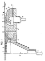
- Fig. 1 einen Meßkopf mit zentralem Meßluftstutzen;
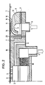
- Fig. 2 eine zweite Ausführungsform des erfindungsgemäßen Meßkopfs mit ringförmig ausgebildetem Meßluftstutzen und in der Meßkammer angeordnetem, ebenfalls ringförmigem Filter;
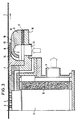
- Fig. 3 eine dritte Ausführungsform des erfindungsgemäßen Meßkopfs mit ringförmig ausgebildetem Meßluftstutzen und einem in der Meßkammer angeordneten Filter in Form eines Hohlzylinders;
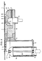
- Fig. 4 eine vierte Ausführungsform des erfindungsgemäßen Meßkopfs mit zentralem Meßluftstutzen und diesen abdeckendem, axial angeordnetem Filter;
- Fig. 5 eine weitere Ausführungsform des erfindungsgemäßen Meßkopfs mit ringförmig ausgebildetem Meßluftstutzen, ringförmigem Filter und zusätzlichem Absaugstutzen zum Anschluß eines Staubsaugers.
- In sämtlichen Figuren ist jeweils nur eine Hälfte des rotationssymmetrischen Meßkopfs in einem Vertikalschnitt dargestellt.
- Gemäß Fig. 1 wird die Bahn aus porösem Material, deren Porosität gemessen werden soll, in der durch einen Pfeil angedeuteten Richtung über die Oberseite des Meßkopfs bewegt. Die Meßkammer 2 wird nach oben hin von einer Meßplatte 3 abgedeckt, in der Meßöffnungen 4 vorgesehen sind. Die Meßkammer 2 mündet unten in einen zentralen Meßluftstutzen 5, an den eine nicht dargestellte Einrichtung zur Erzeugung eines Unterdrucks angeschlossen ist. Während des Meßvorgangs wird Luft durch die poröse Bahn 1 und die Meßöffnungen 4 in die Meßkammer 2 angesaugt. Die Menge der angesaugten Luft, welche mit einer geeigneten Meßeinrichtung gemessen wird, ist ein Maß für die Porosität der Bahn 1. Der in der Meßkammer 2 herrschende Unterdruck, der während der Messung möglichst konstant gehalten wird, kann über einen getrennten Meßkanal 6 separat gemessen werden. Die runde Meßplatte 3 ist von einer ebenfalls runden Leitplatte 7 umgeben. Die Oberseiten der Meßplatte 3 und der Leitplatte 7 liegen bündig, so daß sie eine gemeinsame ebene Fläche bilden, über die die Bahn 1 gleitet. An ihrem äußeren Umfang weist die Leitplatte 7 eine leichte Abschrägung 8 auf. Die Leitplatte 7 überdeckt teilweise einen Blasring 9 von ungefähr kreisabschnittsförmigem Querschnitt und einer ebenen, parallel zur Bahn 1 liegenden Abplattung 10 an seiner Oberseite. An seiner ebenen Unterseite weist der Blasring 9 eine halbkreisförmige Nut 11 auf, welche einen die Meßkammer 2 konzentrisch umgebenden Ringkanal 12 bildet. Während des Meßbetriebs wird über einen Anschlußstutzen 13 Blasluft in den Ringkanal 12 eingeleitet. Der Ringkanal 12 geht in einen rings um die Meßplatte 3 umlaufenden Blasschlitz 14 über, welcher von der gekrümmten Unterseite der Leitplatte 7 und der gegenüberstehenden Oberseite des Blasrings 9 gebildet wird. Die Ausblasöffnung 15 dieses Blasschlitzes 14 ist tangential zur Unterseite der bewegten Bahn 1 nach außen gerichtet. Die durch sie ausströmende Blasluft erzeugt zwischen der Unterseite der Bahn 1 und der kreisförmig gewölbten Außenkontur des Blasrings 9 einen Unterdruck, wodurch die Bahn 1 auf den Rand der Leitplatte 7 gedrückt wird. Eventuell an der Unterseite der Bahn 1 anhaftende Partikel werden dabei nach außen weggeblasen. Die stetige Verjüngung des Blasschlitzes 14 zur Ausblasöffnung 15 hin bewirkt eine genügend hohe Ausblasgeschwindigkeit der strömenden Blasluft. Die Meßplatte 3, die Leitplatte 7 und der Blasring 9 sind gemein- . sam auf eine runde Trägerplatte 16 montiert. Zwischen dieser Trägerplatte 16 und dem Blasring 9 ist ein elastischer Dichtring 17 vorgesehen. Der Blasring 9 ist dabei vertikal so verschiebbar montiert, daß die Dicke des Blasschlitzes 14 durch eine Änderung des Abstands zwischen Blasring 9 und Leitplatte 7 einstellbar ist, wobei der Dichtring 17 elastisch nachgeben kann.
- Die Meßkammer 2 des in Fig. 2 dargestellten zweiten Ausführungsbeispiels des erfindungsgemäßen Meßkopfs zeichnet sich durch einen vergrößerten Durchmesser bei gleichzeitig verringerter Höhe aus. Der Meßluftstutzen 5 ist ringförmig ausgebildet und läuft am unteren Rand der Meßkammer 2 um. Die Meßplatte 3 ist an die Trägerplatte 16 einstückig angeformt. Hierdurch ergibt sich eine insgesamt niedrigere Bauhöhe des Meßkopfs. In der Meßkammer 2 ist ein kreisringförmig ausgebildetes Filter 18 vorgesehen, welches zwischen den Meßöffnungen 4 und dem Meßluftstutzen 5 angeordnet ist. Es dient zur Filterung der durch die Meßkammer 2 strömenden Meßluft, um das empfindliche, an den Meßluftstutzen 5 angeschlossene Meßsystem vor Staub- und Schmutzpartikeln zu schützen.
- Fig. 3 zeigt eine Ausführung des erfindungsgemäßen Meßkopfs, die sich durch ein wesentlich vergrößertes, vor dem ringförmigen Meßluftstutzen 5 angeordnetes Filter 18 in Form eines Hohlzylinders auszeichnet.
- Fig. 4 zeigt eine weitere Ausführungsform des Meßkopfs. Die Meßkammer 2 ist nach unten hin durch einen Deckel 19 abgeschlossen, in den ein zentraler Meßluftstutzen 5 mit ringkreisförmiger Auslaßöffnung eingelassen ist. Das zylindrisch ausgebildete Filter 18 deckt den Meßluftstutzen 5 vollständig ab. Auf der Innenseite des Deckels 19 ist das Filter 18 mittels einer zentralen Haltestange 20 und einer Befestigungskappe 21 lösbar montiert, so daß es leicht ausgetauscht werden kann.
- Bei dem in Fig. 5 dargestellten Meßkopf ist an der der Meßplatte 3 gegenüberliegenden Seite der Meßkammer 2 ein zusätzlicher Absaugstutzen 22 zum Anschluß eines (nicht dargestellten) Staubsaugers vorgesehen. Das Filter 18 befindet sich zwischen diesem Absaugstutzen 22 und dem ringförmig umlaufenden Meßluftstutzen 5. Zur Reinigung des Filters 18 und der Meßkammer 2 wird Spülluft über den Meßluftstutzen 5 entgegen der Strömungsrichtung beim Meßbetrieb durch das Filter 18 in die Meßkammer 2 eingeleitet und über den Absaugstutzen 22 abgesaugt. Wird die Menge der eingeleiteten Spülluft dabei so dosiert, daß sie die durch den Absaugstutzen 22 abgesaugte Luftmenge nicht übersteigt, ist gewährleistet, daß die Meßöffnungen 4 in der Meßplatte 3 stets von außen nach innen und nie umgekehrt durchströmt werden, so daß sich kein Schmutz oder Staub auf der Innenseite der Meßplatte 3 ablagern kann.
Claims (17)
dadurch gekennzeichnet, daß die Vorrichtung zum Ansaugen der Bahn (1) einen umlaufenden Blasschlitz (14) mit tangential zur Unterseite der Bahn (1) nach außen gerichteter Ausblasöffnung (15) aufweist.
Priority Applications (1)
| Application Number | Priority Date | Filing Date | Title |
|---|---|---|---|
| AT86906807T ATE50062T1 (de) | 1985-11-06 | 1986-11-05 | Messkopf fuer die messung der porositaet einer sich bewegenden bahn. |
Applications Claiming Priority (2)
| Application Number | Priority Date | Filing Date | Title |
|---|---|---|---|
| DE3539320 | 1985-11-06 | ||
| DE19853539320 DE3539320A1 (de) | 1985-11-06 | 1985-11-06 | Messkopf fuer die messung der porositaet einer sich bewegenden bahn |
Publications (2)
| Publication Number | Publication Date |
|---|---|
| EP0243481A1 EP0243481A1 (de) | 1987-11-04 |
| EP0243481B1 true EP0243481B1 (de) | 1990-01-31 |
Family
ID=6285283
Family Applications (1)
| Application Number | Title | Priority Date | Filing Date |
|---|---|---|---|
| EP86906807A Expired - Lifetime EP0243481B1 (de) | 1985-11-06 | 1986-11-05 | Messkopf für die messung der porosität einer sich bewegenden bahn |
Country Status (5)
| Country | Link |
|---|---|
| US (1) | US4672841A (de) |
| EP (1) | EP0243481B1 (de) |
| DE (2) | DE3539320A1 (de) |
| FI (1) | FI872765A0 (de) |
| WO (1) | WO1987003089A1 (de) |
Families Citing this family (17)
| Publication number | Priority date | Publication date | Assignee | Title |
|---|---|---|---|---|
| DE3611458A1 (de) * | 1986-04-05 | 1987-10-15 | Wuertt Filztuchfab | Pruefvorrichtung zum pruefen der luftdurchlaessigkeit von flaechigen gegenstaenden, insbesondere von filzen und sieben fuer der papierherstellung dienenden maschinen oder anlagen |
| CH674572A5 (de) * | 1987-10-06 | 1990-06-15 | Textest Ag | |
| US4905500A (en) * | 1988-03-28 | 1990-03-06 | Macmillan Bloedel Limited | Paper web surface cleaner or tester |
| US5172844A (en) * | 1989-01-21 | 1992-12-22 | Bandfabrik Breitenbach Ag | Method and apparatus for reducing a transporting strain on elongated material passing through a treatment chamber |
| DE4302137C2 (de) * | 1993-01-27 | 1999-09-02 | Micro Perforation Engineering | Verfahren und Vorrichtung zur optischen Porositätsmessung an einer laufenden Bahn |
| GB9414540D0 (en) * | 1994-07-19 | 1994-09-07 | At & T Global Inf Solution | Apparatus for assessing the condition of a bank note |
| FI20031273A7 (fi) * | 2003-09-08 | 2005-03-09 | Aca Systems Oy | Menetelmä huokoisuuden mittaamiseksi liikkuvasta rainamaisesta paperista |
| US7274447B2 (en) * | 2004-06-21 | 2007-09-25 | Swce | Material porosity pressure impulse testing system |
| US8282781B2 (en) | 2006-12-11 | 2012-10-09 | Honeywell International Inc. | Apparatus and method for stabilization of a moving sheet relative to a sensor |
| US9045306B2 (en) * | 2007-11-27 | 2015-06-02 | Abb Ltd. | Sheet stabilizer with suction nozzle having center protrusion |
| US8028988B2 (en) * | 2008-01-21 | 2011-10-04 | Honeywell International Inc. | Apparatus and method for stabilizing a moving sheet relative to a sensor |
| US9109330B2 (en) * | 2009-03-09 | 2015-08-18 | Honeywell International Inc. | Apparatus and method for measuring properties of unstabilized moving sheets |
| FI124628B (fi) * | 2011-03-02 | 2014-11-14 | Metso Automation Oy | Huokoisuusmittaus |
| US9007589B2 (en) * | 2013-09-16 | 2015-04-14 | Honeywell Asca Inc. | Co-located porosity and caliper measurement for membranes and other web products |
| CN111157035B (zh) * | 2018-11-07 | 2025-06-24 | 无锡万耐特自动化设备股份公司 | 一种带环形风刀的精密测量头 |
| TWI755842B (zh) * | 2020-09-04 | 2022-02-21 | 奈米趨勢科技有限公司 | 非接觸式塑膠吹袋機薄膜厚度量測裝置 |
| CN118837274B (zh) * | 2024-09-23 | 2025-04-18 | 南通市通州区锦都拉链有限公司 | 一种织带测试设备 |
Family Cites Families (6)
| Publication number | Priority date | Publication date | Assignee | Title |
|---|---|---|---|---|
| US3268222A (en) * | 1964-05-07 | 1966-08-23 | Singer Co | Work fabric transporting devices |
| US3371518A (en) * | 1965-02-12 | 1968-03-05 | Beloit Corp | Device for continuously measuring porosity |
| US3466925A (en) * | 1967-08-09 | 1969-09-16 | Cons Paper Inc | Method and apparatus for measuring porosity |
| US4311037A (en) * | 1980-03-19 | 1982-01-19 | Scott Paper Company | Web permeability tester |
| US4471649A (en) * | 1981-02-20 | 1984-09-18 | British-American Tobacco Company Limited | Permeability monitoring of sheet materials |
| US4505412A (en) * | 1983-10-31 | 1985-03-19 | Crown Zellerbach Corporation | Pneumatic conveyor system for flexible webs |
-
1985
- 1985-11-06 DE DE19853539320 patent/DE3539320A1/de active Granted
-
1986
- 1986-07-03 US US06/882,089 patent/US4672841A/en not_active Expired - Fee Related
- 1986-11-05 DE DE8686906807T patent/DE3668703D1/de not_active Expired - Lifetime
- 1986-11-05 EP EP86906807A patent/EP0243481B1/de not_active Expired - Lifetime
- 1986-11-05 WO PCT/EP1986/000638 patent/WO1987003089A1/de not_active Ceased
-
1987
- 1987-06-22 FI FI872765A patent/FI872765A0/fi not_active IP Right Cessation
Also Published As
| Publication number | Publication date |
|---|---|
| FI872765A7 (fi) | 1987-06-22 |
| FI872765A0 (fi) | 1987-06-22 |
| DE3539320C2 (de) | 1987-08-27 |
| EP0243481A1 (de) | 1987-11-04 |
| DE3668703D1 (de) | 1990-03-08 |
| DE3539320A1 (de) | 1987-05-27 |
| US4672841A (en) | 1987-06-16 |
| WO1987003089A1 (fr) | 1987-05-21 |
Similar Documents
| Publication | Publication Date | Title |
|---|---|---|
| WO1987003089A1 (fr) | Tete de mesure pour determiner la porosite d'une bande en cours de deplacement | |
| DE2006716C3 (de) | Reinigungsvorrichtung zum Absaugen von Staub | |
| EP0041106B1 (de) | Entstauberzyklon, insbesondere mit doppelter Abscheidung | |
| DE19849639C1 (de) | Coanda-Injektor und Druckgasleitung zum Anschluß eines solchen | |
| EP0887460B2 (de) | Verfahren und Vorrichtung zum Reinigen eines Transportbandes | |
| DE2802369A1 (de) | Filtervorrichtung zum filtern von durch staub und faserabfaelle verunreinigter luft | |
| DE3429024C2 (de) | Verfahren und Vorrichtung zum Abscheiden von Staub aus Fasermaterial | |
| EP0476169A1 (de) | Verfahren zum Reinigen eines Zyklons und damit reinigbarer Zyklon | |
| DE3237991C2 (de) | Dralldüsenspinnvorrichtung mit einer Luftstromführungsplatte | |
| DE19702793A1 (de) | Reinigungsvorrichtung | |
| DE1245820B (de) | Vorrichtung zum Bilden eines fortlaufenden Tabakstroms | |
| DE2354967C2 (de) | Vorrichtung zum kontinuierlichen Abtransport von an Spinnstellen abgeschiedenen Verunreinigungen | |
| DE4308286C2 (de) | Verfahren und Vorrichtung zum Abreinigen von mit staubförmigen Partikeln zugesetzten Filterpatronen einer Filteranlage | |
| DE2147443A1 (de) | Schmelz , Saug und Blasgerat, insbesondere fur die Reparatur von elek tronischen Schaltungen | |
| DE2653220C3 (de) | Reinigungsvorrichtung für die steuerbare Fadenklemme einer Düsenwebmaschine | |
| DE29503752U1 (de) | Reinigungsvorrichtung | |
| EP0096311B1 (de) | Prüfeinrichtung zur Messung der Luftdurchlässigkeit von textilen Materialbahnen | |
| DE3446156C2 (de) | Verfahren und Vorrichtung zum Herstellen einer ein- oder mehrschichtigen Bahn aus einem im wesentlichen trockenen Faser- und/oder Teilchenmaterial | |
| DE8809870U1 (de) | Vorrichtung zum Ablegen eines textilen Faserbandes in eine Kanne | |
| DE19506470C2 (de) | Gleitplatte und deren Verwendung | |
| DE3917991A1 (de) | Vorrichtung zum oe-rotorspinnen | |
| DE3716585C2 (de) | Einrichtung zum Abtrennen verschiedener Stoffe aus einem Stoffgemenge, insbesondere zum Trennen von Müll | |
| EP0062781B1 (de) | Offenendspinnmaschine | |
| EP1033082B1 (de) | Vorrichtung zum Aufbauen eines kontinuierlichen Tabakstranges | |
| DE3834810C2 (de) |
Legal Events
| Date | Code | Title | Description |
|---|---|---|---|
| PUAI | Public reference made under article 153(3) epc to a published international application that has entered the european phase |
Free format text: ORIGINAL CODE: 0009012 |
|
| 17P | Request for examination filed |
Effective date: 19870727 |
|
| AK | Designated contracting states |
Kind code of ref document: A1 Designated state(s): AT BE CH DE FR GB IT LI LU NL SE |
|
| 17Q | First examination report despatched |
Effective date: 19890124 |
|
| GRAA | (expected) grant |
Free format text: ORIGINAL CODE: 0009210 |
|
| AK | Designated contracting states |
Kind code of ref document: B1 Designated state(s): AT BE CH DE FR GB IT LI LU NL SE |
|
| REF | Corresponds to: |
Ref document number: 50062 Country of ref document: AT Date of ref document: 19900215 Kind code of ref document: T |
|
| ITF | It: translation for a ep patent filed | ||
| REF | Corresponds to: |
Ref document number: 3668703 Country of ref document: DE Date of ref document: 19900308 |
|
| GBT | Gb: translation of ep patent filed (gb section 77(6)(a)/1977) | ||
| ET | Fr: translation filed | ||
| PGFP | Annual fee paid to national office [announced via postgrant information from national office to epo] |
Ref country code: SE Payment date: 19901030 Year of fee payment: 5 |
|
| PGFP | Annual fee paid to national office [announced via postgrant information from national office to epo] |
Ref country code: GB Payment date: 19901105 Year of fee payment: 5 |
|
| PGFP | Annual fee paid to national office [announced via postgrant information from national office to epo] |
Ref country code: CH Payment date: 19901108 Year of fee payment: 5 |
|
| PGFP | Annual fee paid to national office [announced via postgrant information from national office to epo] |
Ref country code: BE Payment date: 19901114 Year of fee payment: 5 |
|
| PGFP | Annual fee paid to national office [announced via postgrant information from national office to epo] |
Ref country code: AT Payment date: 19901115 Year of fee payment: 5 |
|
| PGFP | Annual fee paid to national office [announced via postgrant information from national office to epo] |
Ref country code: FR Payment date: 19901119 Year of fee payment: 5 |
|
| PLBE | No opposition filed within time limit |
Free format text: ORIGINAL CODE: 0009261 |
|
| STAA | Information on the status of an ep patent application or granted ep patent |
Free format text: STATUS: NO OPPOSITION FILED WITHIN TIME LIMIT |
|
| ITTA | It: last paid annual fee | ||
| PG25 | Lapsed in a contracting state [announced via postgrant information from national office to epo] |
Ref country code: LU Free format text: LAPSE BECAUSE OF NON-PAYMENT OF DUE FEES Effective date: 19901130 |
|
| PGFP | Annual fee paid to national office [announced via postgrant information from national office to epo] |
Ref country code: NL Payment date: 19901130 Year of fee payment: 5 Ref country code: LU Payment date: 19901130 Year of fee payment: 5 |
|
| PGFP | Annual fee paid to national office [announced via postgrant information from national office to epo] |
Ref country code: DE Payment date: 19901213 Year of fee payment: 5 |
|
| 26N | No opposition filed | ||
| EPTA | Lu: last paid annual fee | ||
| PG25 | Lapsed in a contracting state [announced via postgrant information from national office to epo] |
Ref country code: GB Effective date: 19911105 Ref country code: AT Effective date: 19911105 |
|
| PG25 | Lapsed in a contracting state [announced via postgrant information from national office to epo] |
Ref country code: SE Effective date: 19911106 |
|
| PG25 | Lapsed in a contracting state [announced via postgrant information from national office to epo] |
Ref country code: LI Effective date: 19911130 Ref country code: CH Effective date: 19911130 Ref country code: BE Effective date: 19911130 |
|
| NLT1 | Nl: modifications of names registered in virtue of documents presented to the patent office pursuant to art. 16 a, paragraph 1 |
Owner name: STEINBEIS GESSNER GMBH TE BRANNENBURG, BONDSREPUBL |
|
| REG | Reference to a national code |
Ref country code: FR Ref legal event code: CD Ref country code: FR Ref legal event code: CA |
|
| BERE | Be: lapsed |
Owner name: GESSNER & CO. G.M.B.H. Effective date: 19911130 |
|
| PG25 | Lapsed in a contracting state [announced via postgrant information from national office to epo] |
Ref country code: NL Effective date: 19920601 |
|
| GBPC | Gb: european patent ceased through non-payment of renewal fee | ||
| NLV4 | Nl: lapsed or anulled due to non-payment of the annual fee | ||
| PG25 | Lapsed in a contracting state [announced via postgrant information from national office to epo] |
Ref country code: FR Effective date: 19920731 |
|
| REG | Reference to a national code |
Ref country code: CH Ref legal event code: PL |
|
| REG | Reference to a national code |
Ref country code: FR Ref legal event code: ST |
|
| PG25 | Lapsed in a contracting state [announced via postgrant information from national office to epo] |
Ref country code: DE Effective date: 19921103 |
|
| EUG | Se: european patent has lapsed |
Ref document number: 86906807.2 Effective date: 19920604 |
|
| PG25 | Lapsed in a contracting state [announced via postgrant information from national office to epo] |
Ref country code: IT Free format text: LAPSE BECAUSE OF NON-PAYMENT OF DUE FEES;WARNING: LAPSES OF ITALIAN PATENTS WITH EFFECTIVE DATE BEFORE 2007 MAY HAVE OCCURRED AT ANY TIME BEFORE 2007. THE CORRECT EFFECTIVE DATE MAY BE DIFFERENT FROM THE ONE RECORDED. Effective date: 20051105 |