EP0243095A2 - Verfahren und Einrichtung zum Giessen von Gegenständen - Google Patents
Verfahren und Einrichtung zum Giessen von Gegenständen Download PDFInfo
- Publication number
- EP0243095A2 EP0243095A2 EP87303353A EP87303353A EP0243095A2 EP 0243095 A2 EP0243095 A2 EP 0243095A2 EP 87303353 A EP87303353 A EP 87303353A EP 87303353 A EP87303353 A EP 87303353A EP 0243095 A2 EP0243095 A2 EP 0243095A2
- Authority
- EP
- European Patent Office
- Prior art keywords
- base plate
- distribution system
- article molds
- mold
- molten metal
- Prior art date
- Legal status (The legal status is an assumption and is not a legal conclusion. Google has not performed a legal analysis and makes no representation as to the accuracy of the status listed.)
- Withdrawn
Links
Images


Classifications
-
- B—PERFORMING OPERATIONS; TRANSPORTING
- B22—CASTING; POWDER METALLURGY
- B22D—CASTING OF METALS; CASTING OF OTHER SUBSTANCES BY THE SAME PROCESSES OR DEVICES
- B22D33/00—Equipment for handling moulds
- B22D33/04—Bringing together or separating moulds
Definitions
- the present invention relates to a new and improved method and apparatus for casting a plurality of articles.
- Ceramic mold structures having a construction similar to that disclosed in U.S. Patent Nos. 3,810,504 and 3,915,761 may be used to cast a plurality of articles. These mold structures include a plurality of open ended article molds disposed in a circular array. Upper end portions of the article molds are connected with a distribution system into which molten metal is poured. Lower end portions of the article molds are cooled by a chill plate.
- a new and improved method and apparatus for casting articles reduces thermal stresses in a mold structure to enable fluid tight seals to be maintained between a plurality of article molds and a chill plate. Reducing thermal stresses in the mold structure also prevents cracking of article molds. This is accomplished by providing relative movement between sections of a base plate connected with the lower end portions of the article molds. The sections of the base plate are moved relative to each other by thermal expansion forces transmitted from a molten metal distribution system connected with the upper end portions of the article molds.
- the base plate may be formed as one piece with the sections interconnected. Areas of stress concentration are provided in the base plate at locations spaced from connections between the article molds and the base plate. During a casting operation, thermal expansion forces cause the base plate to crack at the areas of stress concentration to separate the various sections of the base plate. The sections of the base plate can then move relative to each other under the influence of the thermal expansion forces.
- the relative movement between the sections of the base plate allows bottom surface areas of the sections of the base plate to remain in abutting engagement with an upper side surface of a chill plate to prevent run outs from the article mold cavities.
- the relative movement between the sections of the base plate tends to minimize thermal stresses in the article molds in such a manner as to retard cracking of the article molds.
- Concentration of thermal stresses in selected areas of the base plate can be accomplished by weakening the selected areas of the base plate.
- slots and/or grooves can be formed in the base plate at locations spaced from the article molds.
- thermal stresses are concentrated at the slots and/or grooves.
- thermal stresses can be concentrated in preselected areas of the base plate by providing bodies of material having a relatively high coefficient of thermal expansion in the base plate. Up on heating of the base plate, the bodies having a relatively high coefficient of thermal expansion expand to a greater extent than the material of the base plate with a resulting cracking of the base plate.
- Another object of this invention is to provide a new and improved method and apparatus for casting a plurality of articles and wherein stresses in a base plate of a mold are relieved by cracking the base plate at a plurality of locations spaced from connections between the base plate and article molds.
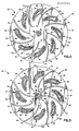
- a one-piece ceramic mold structure 20 (Fig. 1) is used in casting a plurality of articles, such as turbine blades.
- the mold structure 20 has a circular base plate 22 having a flat bottom surface 24.
- the bottom surface 24 of the base plate 22 is disposed in flat abutting engagement with an upper side surface 26 of a circular chill plate 28.
- a plurality of open ended article molds 32 are disposed in a circular array (see Fig. 2) and extend upwardly from the base plate 22 to a molten metal distribution system 36.
- the ceramic article molds 32 have open ended lower portions 40 which are connected with the base plate 22.
- the open ended lower portions 40 of the article molds 32 enable heat to be conducted from molten metal in article mold cavities 42 to the chill plate 28. This promotes solidification of the molten me tal in a direction extending upwardly from the chill plate 29.
- the mold 20 is adapted to make columnar grained cast articles, such as turbine blades, it is contemplated that the mold could be constructed to form either single crystal or equiaxed articles if desired.
- the ceramic molten metal distribution system 36 is fixedly connected with the upper ends of the article molds 32.
- the molten metal distribution system 36 includes a generally conical pour cup 50 which is disposed in a coaxial relationship with the circular base plate 22 and circular array of article molds 32.
- the pour cup 50 is connected in fluid communication with the article mold cavities 42 by passages 52 formed in runners or arms 54 which extend radially outwardly from the pour cup 50 to the upper end portions of the article molds 32.
- the mold 20 is preheated to a relatively high temperature, for example, 2700 degrees F.
- Molten metal for example a nickel chrome super alloy
- the molten metal is conducted through the runners 54 to the article molds 32 to fill the open ended article mold cavities 42.
- the molten metal of the lower end portions of the article mold cavities 42 quickly solidifies in the manner indicated at 56 in Fig. 3.
- the metal in the upper end portions of the article mold cavities 42 and in the distribution system 36 remains molten. Since the upper end portion of the one-piece ceramic mold structure 20 is at a higher temperature than the lower portion of the mold structure, the upper portion expands to a greater extent than the lower portion of the mold structure.
- the greater thermal expansion of the upper portion of the mold structure 20 results in thermal expansion forces which tend to tip the article molds 32 outwardly, that is in the direction of the arrows 58 in Fig. 1. As this occurs, the portions of the article molds 32 closest to the center of the mold structure 20 tend to lift upwardly away from the upper surface 26 of the chill plate 28. This promotes a running out of molten metal from the open ends of the article mold cavities 42 in such a manner as to result in the formation of one or more defective castings.
- the thermal expansion forces applied by the molten metal distribution system 36 against the upper ends of the article molds 42 also stresses the ceramic material of the article molds 32 and base plate 22. This can result in the formation of cracks at the connections between the lower end portions 40 of the article molds 32 and the base plate 22. Molten metal may run out of the article mold cavities 42 through these cracks and result in defective castings.
- thermal stresses in the mold structure 20 are minimized by forming the base plate 22 in a plurality of sections 62 (Fig. 2) which are moved relative to each other. This movement accomodates thermal expansion of the molten metal distribution system 36 relative to the article molds 32 and base plate 22.
- the base plate 22 may be initially formed with the sections 62 interconnected by a central portion 64 of the base plate in the manner shown in Fig. 2.
- the thermal expansion of the molten metal distribution system 36 relative to the base plate 22 results in forces being transmitted from the molten metal distribution system to the base plate. These forces are concentrated in selected areas of the base plate 22 to form stress relieving cracks 68 (Fig. 3).
- the cracks 68 are formed at preselected locations which are spaced from connections between the article molds 32 and the base plate 22 so that the article molds and their connections with the base plate are maintained free of cracks.
- the cracks 68 separate the sections 62 of the base plate.
- the separate sections of the base plate are moved relative to each other by thermal expansion forces transmitted from the molten metal distribution system 36 through the article molds 32.
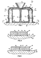
- the relative movement between the sections 62 of the base plate 22 result in the bottom surfaces 24 of the base plate sections being maintained in flat abutting engagement with the upper surface 26 of the chill plate 28 (Figs. 4 and 5).
- areas of stress concentration are provided in the base plate 22 at locations spaced from connections between article molds 32 and the base plate so that the yield or fracture point of the base plate is such that it will fracture in response to the thermal stress in the mold 20 before the article molds 32 are moved or tipped sufficiently to open the joints between the article molds and the chill plate 28 and/or to fracture the mold 20 at the connections between the article molds and base plate.
- the thermal stresses induced during preheating of the mold structure 20 may be sufficiently concentrated in weakened areas of the base plate 22 to cause the stress relieving cracks 68 to form.
- handling of the mold structure 20 is facilitated if the base plate 22 is formed with sufficient strength to resist the thermal stresses induced during preheating of the mold structure.
- the cracks 68 form in areas of stress concentrated upon pouring of molten metal into the distribution system 36.
- An optimum combination of handling strength and thermal stress relief may be obtained by concentrating stresses in the base plate 22 in such a manner that a portion of the cracks 68 are formed during preheating of the mold structure 20 and the remainder of the cracks are formed upon pouring of the molten metal.
- the separate sections 62 of the base plate are moved radially outwardly, through relatively small distances, by thermal expansion forces. This results in the bottom surface 24 of the base plate 22 being maintained in flat abutting engagement with the upper surface 26 of the chill plate 28 to prevent a run out of molten metal from the open lower end portions of the article mold cavities 42.
- the stresses in the base plate 22 are relieved as the cracks 68 are formed in the central portion 64 (Fig. 3) of the base plate. Therefore, cracks are not formed at the connections between the article molds 32 and the base plate 22.
- the slots 72 extend between opposite major circular side surfaces 24 and 74 (Fig. 4) of the ceramic base plate 22.
- the slots extend from a circular outer edge 76 of the base plate 22 (Fig. 2) to end surfaces 78 adjacent the central portion 64 of the base plate.
- the slots 72 divide the one-piece base plate 22 into a plurality of interconnected sections 62.
- the base plate 22 is weakened by the slots 22, it is formed as one-piece and has sufficient strength to enable it to be handled during formation of the mold 20 and the setting up of the mold in a furnace.
- the slots 72 concentrate stresses in the central portion 64 of the base plate 22. These stresses are sufficient to form cracks 68 (Fig. 3) which extend between opposite major side surfaces 24 and 74 (Fig. 5) of the base plate 22.
- the cracks 68 ra diate inwardly from the inner end surfaces 78 of the slots 72 to the central portion 64 of the base plate and around a support post 82 which extends upwardly to the molten metal distribution system 36.
- the cracks 68 extend axially through the circular base plate 22, they separate the sections 62 of the base plate. This allows the sections 62 of the base plate to be moved relative to each other to relieve the thermal stresses in the base plate and to maintain the bottom surface 24 of the base plate in flat abutting engagement with the top surface 26 of the chill plate 28 during thermal expansion of the molten metal distribution system 36 relative to the base plate. Since the slots 72 extend radially inwardly from the circular outer edge 76 of the base plate 22 to end surfaces 78 disposed inwardly of the article molds 32, the cracks 68 will be formed in the central portion 64 of the base plate at locations radially inwardly of the circular array of article molds 32. This results in the connections between the article molds 32 and the base plate 22 being maintained free of cracks.
- the slots 72 have been illustrated in Figs. 2 and 3 as having open outer ends at the circular edge 76 of the base plate, the ends of the slots could be closed to increase the strength of the base plate 22 prior to performing a casting operation. If desired, the slots 72 could be closed at the radially outer ends and interconnected at their radially inner ends. Although it is preferred to provide a slot 72 between each of the article molds 32 so that there is only one article mold on each section 62, the number of slots 72 could be reduced so that there would be two or even three molds connected with one of the sections 62. Thus, a single slot could be provided to divide the base plate into only two sections.
- stresses in the ceramic base plate 22 are concentrated in the central portion 64 of the base plate by the slots 72.
- stresses in the ceramic base plate 22 are concentrated by providing bodies of expansion material in the base plate. Since the embodiment of the invention shown in Figs. 6 and 7 is generally similar to the embodiment of the invention shown in Figs. 1-5, similar numerals will be utilized to designate similar components, the suffix letter "a" being associated with the numerals of Figs. 6 and 7 to avoid confusion.
- the one-piece ceramic mold structure 20a (Fig. 6) has a circular base plate 22a.
- a plurality of article molds 32a are connected with an extent upwardly from the base plate.
- the article molds 32a have mold cavities 42a with open lower ends which are exposed to the upper side surface of a chill plate.
- the article molds 32a extend upwardly from the base plate 22a to a molten metal distribution system (not shown) having a construction which is the same as the construction of the molten metal distribution system 36 of Fig. 1. It should be understood that the mold structure 20a of Fig. 6 has the same general construction as the mold structure 20 of Figs. 1 and 2.
- bodies 88 (Fig. 7) of expansion material are disposed in the ceramic material of the base plate 22a.
- bodies 88 of expansion material are strips having a rectangular cross-sectional configuration and a length which is approximately the same as the length of the slots 72 of Fig. 2.
- the strips 88 of expansion material extend from a circular outer side surface 76a of the base plate 22a to a central portion 64a of the base plate.
- the strips 88 of expansion material are covered by ceramic material of the base plate 22a in a manner which results in the formation of a plurality of ridges 90 which divide the base plate into a plurality of sections 62a.
- the bodies 88 o f expansion material have a coefficient of thermal expansion which is greater than the coefficient of thermal expansion of the ceramic material forming base plate 22a.
- the strips 88 of expansion material were formed of a polymeric material which is commercially available under the trademark "Teflon”.
- the coefficient of thermal expansion of "Teflon" that is, the change in length per unit length per degree change in temperature, is approximately 110 per degree C.
- the base plate 22a is made of a ceramic mold material.
- the entire mold structure 20a, including base plate 22a, is formed by repeatively dipping a pattern in a liquid slurry of ceramic mold material.
- the slurry of ceramic mold material contains fused silica, zircon and other refractory materials in combination with binder. Chemical binders such as ethyl silicate, sodium silicate and colloidal silica can be utilized.
- the slurry may contain suitable film formers such as alginates to control viscosity and wetting agents to control flow characteristics and pattern wettability.
- the ceramic mold material of the base plate 22a has a coefficient of thermal expansion of approximately 10 per degree C. It should be understood that the mold structure 20 is formed in the same way and of the same ceramic material as the mold structure 20a.
- the mold structure 20a is placed in a furnace on a chill plate 28a and is preheated to approximately 2,700 degrees F.
- the bodies 88 of expansion material thermally expand to a greater extent than the ceramic material of the base plate 22a. Due to the relatively large expansion of the bodies 88, cracks are formed in the one-piece base plate 22a during preheating of the mold structure 20a. These cracks extend along the ridges 90 from the circular outer side surfaces 76a to the central portion 64a of the base plate 22a. However, the cracks do not intersect so as to divide the base plate into separate sections.
- the molten metal flows outwardly through runners to each of the article mold cavities 42a.
- the molten metal in the lower end portion of the article mold cavities 42a immediately solidifies.
- the metal in the distribution system remains molten. Therefore, there is thermal expansion of the distribution system relative to the relatively cool case plate 22a.
- thermal expansion forces are transmitted from the molten metal distribution system to the article molds 32a to the base plate 22a. These thermal expansion forces cause the cracks which were formed at the ridges 90 to extend into the central portion 64a of the base plate.
- the cracks intersect in the central portion 64a of the base plate to separate the sections 62a of the base plate in the same manner as in which the cracks 68 of Fig. 3 separate the sections 62 of the base plate 22.
- the bodies 88 of expansion material extend radially inwardly from the circular outer side surface 76a of the base plate to the central portion 64a of the base plate in the same manner as the slots 72.
- the bodies 88 of thermal expansion material could extend from locations adjacent to and radially inwardly of the outer side surface 76a of the base plate to locations closer to the support post 82a in the central portion 64a of the base plate.
- the bodies of expansion material 88 could extend from the side surface 76a and be interconnected at the central portion 64a of the base plate.
- the one-piece ceramic mold structure 20b of Fig. 8 has a circular base plate 22b which is disposed on a chill plate 28b.
- a plurality of article molds extend upwardly from the base plate 22b to a molten metal distribution system (not shown) in the same manner as illustrated in Fig. 1 for the mold structure 20.
- the mold structure 20b has the same general construction as the mold structures 20 and 20a.
- the grooves 96 extend between and are spaced from the article molds in the same manner in which the slots 72 of Fig. 2 are spaced from the article molds 32. Like the slots 72 of Fig. 2, the grooves 96 extend from a circular outer edge (not shown) of the base plate 22b to a central portion of the base plate.
- the molten metal distribution system When the molten metal is poured into the mold 20b, the molten metal distribution system remains relatively hot while the base plate 22b remains relatively cool under the influence of the chill plate 28b. This results in the molten metal distribution system expanding to a greater extent than the base plate 22b. Thermal expansion forces are transmitted from the molten metal distribution system through the article molds to the base plate 22b.
- the cracks extend axially through the circular base plate 22b and separate the base plate into a plurality of sections 62b.
- the sections 62b can be moved relative to each other to maintain the lower side surface 24b of the base plate 22b in flat abutting engagement with the upper side surface 26b of the chill plate 28b. Since the cracks are formed in the base plate 22b at locations spaced from the article molds, that is at locations where the grooves 96 are formed or in the central portion of the base plate, the article molds and their connections with the base plate 22b are maintained free of cracks during the casting operation.
- the present invention may advantageously be used with a one-piece ceramic mold structure
- the invention may also be used with a two-piece ceramic mold assembly 104 illustrated in Fig. 9. Since the mold assembly 104 of Fig. 9 has many components which are similar to the components of the mold structure 20 of Fig. 1, similar numerals will be utilized to designate similar components, the suffix letter "c" being associated with the embodiment of the invention shown in Fig. 9 to avoid confusion.
- the mold assembly 104 of Fig. 9 includes a one-piece upper ceramic mold structure 106 and a one-piece lower ceramic mold structure 108.
- the upper and lower mold structures 106 and 108 are interconnected at a plurality of separable joints 110.
- the upper and lower mold structures 106 and 108 can be separated to enable the lower mold structure 108 to be removed from a furnace while the upper mold structure 106 remains in the furnace.
- a molten metal distribution system 36c includes a primary molten metal distribution system 114 in the upper mold structure 106 and a secondary molten metal distribution system 116 in the lower mold structure 108.
- the primary and secondary molten metal distribution systems 114 and 116 are connected in fluid communication with each other through the joints 110.
- the primary molten metal distribution system 114 includes a pour cup 50c and a plurality of hollow runners 54c.
- the secondary molten metal distribution system 116 includes a hollow annular ceramic ring 120 which is integrally formed with and fixedly connected to upper end portions of a plurality of ceramic article molds 32c. A passage in the hollow ring 120 is connected in fluid communication with open ended mold cavities in the article molds 32c.
- Lower end portions 40c of the article molds 32c are integrally formed with and fixedly connected to an annular ceramic base plate 22c.
- the annular ceramic base plate 22c circumscribes a circular baffle plate 124 which is connected with the pour cup 50c by a support post 84c.
- the baffle plate 124 is disposed in a circular opening in the center of the base plate 22c.
- plurality of slots 72c extend radially inwardly from a circular outer side surface 76c of the base plate 22c.
- the slots 72c stop short of a circular inner side surface 130 of the annular base plate 22c. Therefore, arcuate sections 62c of the base plate 22c are interconnected at the central portion of the base plate.
- the mold assembly 104 When a plurality of articles are to be cast with the mold assembly 104, the mold assembly is placed on a chill plate which is raised into a furnace. The upper mold structure 106 is connected with an upper end wall of the furnace. Molten metal is then poured into the pour cup 50c. The molten metal flows from the pour cup 50c through the primary distribution system 114 and joints 110 to the secondary distribution system 74. The molten metal then flows from the annular ring 120 of the secondary distribution system 116 to the article molds 32c.
- the annular ring section 120 of the secondary distribution system 116 is fixedly connected with the upper end portions of the ceramic molds 32c. Since the base plate 22c disposed on a chill plate and the metal in the lower end portions of the open ended cavities in the article molds 32c are exposed to the chill plate, the secondary molten metal distribution system 116 will be at a higher te mperature than the base plate 22c. The resulting thermal expansion of the distribution ring 120 relative to the base plate 22c results in thermal expansion forces being transmitted from the secondary distribution system 116 through the article molds 32c to the base plate 22c.
- the slots 72c concentrate the stresses induced by the thermal expansion forces to crack the base plate 22c.
- the cracks extend from radially inner most end portions of the slots 72c to the circular inner surface 130 of the base plate. This results in the sections 62c of the base plate 22c being separated from each other.
- the base sections 62c can then be moved radially outwardly by thermal expansion forces to maintain a flat bottom surface of the base plate 22c in abutting engagement with an upper surface of the chill plate.
- the cracks in the base plate 22c are formed at locations spaced from the connections between the article molds 34c and the base plate 22c.
- the lower mold structure 108 is gradually lowered from the furnace. As this occurs, the upper and lower mold structures 106 and 108 separate at the joints 110 and the article molds 32c move downwardly past the stationary baffle plate 124.
- the baffle plate 124 blocks the radiation of heat from the portion of the article molds disposed above the baffle plate 124 to the chill plate and the outside of the furnace.
- open ended slots 72c have been utilized in the embodiment of the invention shown in Fig. 9 to concentrate thermal stresses at selected areas in the base plate 22c
- closed ended slots could be used if desired.
- the slots could begin and end in the ceramic base plate 22c.
- open ended slots it is contemplated that the open ends of the slots could be provided at the inner edge 130 and the slots terminated before they reach the outer edge 76c.
- the base plates have been initially formed as one piece with a plurality of interconnected sections.
- the base plate is initially formed as a plurality of separate pieces. Since the embodiment of the invention shown in Fig. 10 is generally similar to the embodiment of the invention shown in Figs. 1-9, similar numerals will be utilized to designate similar components, the suffix letter "d" being associated with the numerals of Fig. 10 to avoid confusion.
- a one-piece ceramic mold structure 20d (Fig. 10) includes a circular ceramic base plate 22d.
- a plurality of ceramic article molds 32d extend upwardly from the base plate 22d to a molten metal distribution system having the same construction as the molten metal distribution system 36 of Fig. 1. It should be understood that the mold structure 20d has the same general construction as the mold of 20 of Fig. 1.
- the base plate 22d is divided into a plurality of separate sections 62d by slots 72d.
- the slots 72d extend inwardly from a circular outer edge or side 76d of the base plate 22d to an intersection 134 in a central portion 64d of the base plate 22d. Since the slots intersect at the central portion 64d of the base plate 22d, it is not necessary the crack the base plate to separate the sections 62d of the base plate in the manner explained in conjunction with the embodiments of the invention shown in Figs. 1-9.
- a pair of article molds 32d extend upwardly from each of the sections 62d of the base plate 22d to the molten metal distribution system.
- the rigid ceramic molten metal distribution system is fixedly connected with the upper ends of the article molds 32d.
- the base plate 22d is disposed on a chill plate.
- Molten metal is poured into the distribution system and is then conducted to open ended article mold cavities 42d in the molds 32d.
- Molten metal in the lower end portions of the article mold cavities 42d is cooled by the chill plate and solidifies while the metal in the distribution system remains molten.
- Thermal expansion forces are transmitted from the molten metal distribution system to the base plate 22d by the article molds 32d. These thermal expansion forces move the sections 62d outwardly to maintain the bottom surfaces of the base plate sections 62d in flat abutting engagement with the upper side surface of the chill plate. This prevents a running out of molten metal from the open lower end portions of the article mold cavities 32d.
- a new and improved method and apparatus for casting articles reduces thermal stresses in a mold structure 20 to enable fluid tight seals to be maintained between a plurality of article molds 32 and a chill plate 28. Reducing thermal stresses in the mold structure 20 also prevents cracking of article molds 32. This is accomplished by providing relative movement between sections 62 of a base plate 22 connected with the lower end portions of the article molds 32. The sections 62 of the base plate 22 are moved relative to each other by thermal expansion forces transmitted from a molten metal distribution system 36 connected with the upper end portions of the article molds 32.
- the base plate 22 may be formed as one piece with the sections 62 interconnected. Areas of stress concentration are provided in the base plate 22 at locations spaced from connections between the article molds and the base plate 22. During a casting operation, thermal expansion forces cause the base plate 22 to crack at the areas of stress concentration to separate the various sections of the base plate. The sections 62 of the base plate 22 can then move relative to each other under the influence of the thermal expansion forces.
- the relative movement between the sections 62 of the base plate 22 allows bottom surface areas 24 of the sections of the base plate to remain in abutting engagement with an upper side surface 26 of a chill plate 28 to prevent run outs from the article mold cavities 42.
- the relative movement between the sections 62 of the base plate 22 tends to minimize thermal stresses in the article molds 32 in such a manner as to retard cracking of the article molds.
- Concentration of thermal stresses in selected areas of the base plate 22 can be accomplished by weakening the selected areas of the base plate.
- slots 72 and/or grooves 96 can be formed in the base plate 22 at locations spaced from the article molds 32.
- thermal stresses are concentrated at the slots 72 and/or grooves 96.
- thermal stresses can be concentrated in preselected areas of the base plate 22 by providing bodies 88 of material having a relatively high coefficient of thermal expansion in the base plate. Upon heating of the base plate, the bodies 88 having a relatively high coefficient of thermal expansion expand to a greater extent than the material of the base plate with a resulting cracking of the base plate.
Landscapes
- Engineering & Computer Science (AREA)
- Mechanical Engineering (AREA)
- Continuous Casting (AREA)
- Molds, Cores, And Manufacturing Methods Thereof (AREA)
Applications Claiming Priority (2)
| Application Number | Priority Date | Filing Date | Title |
|---|---|---|---|
| US854301 | 1986-04-21 | ||
| US06/854,301 US4667728A (en) | 1986-04-21 | 1986-04-21 | Method and apparatus for casting articles |
Publications (2)
| Publication Number | Publication Date |
|---|---|
| EP0243095A2 true EP0243095A2 (de) | 1987-10-28 |
| EP0243095A3 EP0243095A3 (de) | 1988-05-11 |
Family
ID=25318300
Family Applications (1)
| Application Number | Title | Priority Date | Filing Date |
|---|---|---|---|
| EP87303353A Withdrawn EP0243095A3 (de) | 1986-04-21 | 1987-04-15 | Verfahren und Einrichtung zum Giessen von Gegenständen |
Country Status (4)
| Country | Link |
|---|---|
| US (1) | US4667728A (de) |
| EP (1) | EP0243095A3 (de) |
| JP (1) | JPS62296936A (de) |
| AU (1) | AU7180587A (de) |
Cited By (3)
| Publication number | Priority date | Publication date | Assignee | Title |
|---|---|---|---|---|
| DE10047397A1 (de) * | 2000-09-26 | 2002-05-08 | Ald Vacuum Techn Ag | Verfahren zum Schmelzen und gerichteten Erstarren eines Metalls und Vorrichtung hierzu |
| GB2373467A (en) * | 2001-03-22 | 2002-09-25 | Rolls Royce Plc | Mould support arrangement |
| EP1604753A1 (de) * | 2004-05-06 | 2005-12-14 | United Technologies Corporation | Genauguss |
Families Citing this family (5)
| Publication number | Priority date | Publication date | Assignee | Title |
|---|---|---|---|---|
| US4730657A (en) * | 1986-04-21 | 1988-03-15 | Pcc Airfoils, Inc. | Method of making a mold |
| US20050158517A1 (en) * | 2004-01-15 | 2005-07-21 | Sealed Air Corporation (Us) | Corrugated foam/film laminates for use as floor underlayment |
| JP5422304B2 (ja) * | 2009-08-26 | 2014-02-19 | 三菱重工業株式会社 | タービン翼用鋳型およびタービン翼の製造方法 |
| US9381569B2 (en) * | 2013-03-07 | 2016-07-05 | Howmet Corporation | Vacuum or air casting using induction hot topping |
| JP5646025B2 (ja) * | 2013-09-27 | 2014-12-24 | 三菱重工業株式会社 | タービン翼用鋳型およびタービン翼の製造方法 |
Family Cites Families (5)
| Publication number | Priority date | Publication date | Assignee | Title |
|---|---|---|---|---|
| GB1269833A (en) * | 1969-07-11 | 1972-04-06 | Rolls Royce | A method and apparatus for producing a metal article |
| US3810504A (en) * | 1971-03-26 | 1974-05-14 | Trw Inc | Method for directional solidification |
| US3915761A (en) * | 1971-09-15 | 1975-10-28 | United Technologies Corp | Unidirectionally solidified alloy articles |
| US4062399A (en) * | 1975-12-22 | 1977-12-13 | Howmet Turbine Components Corporation | Apparatus for producing directionally solidified castings |
| US4270594A (en) * | 1978-11-02 | 1981-06-02 | Chumakov Vasily A | Method and apparatus for producing directionally solidifying cast pieces |
-
1986
- 1986-04-21 US US06/854,301 patent/US4667728A/en not_active Expired - Fee Related
-
1987
- 1987-04-15 EP EP87303353A patent/EP0243095A3/de not_active Withdrawn
- 1987-04-21 JP JP62098463A patent/JPS62296936A/ja active Pending
- 1987-04-21 AU AU71805/87A patent/AU7180587A/en not_active Abandoned
Cited By (6)
| Publication number | Priority date | Publication date | Assignee | Title |
|---|---|---|---|---|
| DE10047397A1 (de) * | 2000-09-26 | 2002-05-08 | Ald Vacuum Techn Ag | Verfahren zum Schmelzen und gerichteten Erstarren eines Metalls und Vorrichtung hierzu |
| DE10047397B4 (de) * | 2000-09-26 | 2004-02-05 | Ald Vacuum Technologies Ag | Vorrichtung zum Schmelzen und gerichteten Erstarren eines Metalls |
| GB2373467A (en) * | 2001-03-22 | 2002-09-25 | Rolls Royce Plc | Mould support arrangement |
| US6598657B2 (en) | 2001-03-22 | 2003-07-29 | Rolls-Royce Ple | Mould support arrangement |
| GB2373467B (en) * | 2001-03-22 | 2004-04-14 | Rolls Royce Plc | Mould support arrangement |
| EP1604753A1 (de) * | 2004-05-06 | 2005-12-14 | United Technologies Corporation | Genauguss |
Also Published As
| Publication number | Publication date |
|---|---|
| EP0243095A3 (de) | 1988-05-11 |
| JPS62296936A (ja) | 1987-12-24 |
| AU7180587A (en) | 1987-10-22 |
| US4667728A (en) | 1987-05-26 |
Similar Documents
| Publication | Publication Date | Title |
|---|---|---|
| US4637449A (en) | Component casting | |
| US5072771A (en) | Method and apparatus for casting a metal article | |
| US3376915A (en) | Method for casting high temperature alloys to achieve controlled grain structure and orientation | |
| EP0398895B1 (de) | Giessen von turbinenteilen mit integrierten schaufeln | |
| US6510889B2 (en) | Directional solidification method and apparatus | |
| US4549599A (en) | Preventing mold and casting cracking in high rate directional solidification processes | |
| US4667728A (en) | Method and apparatus for casting articles | |
| US4724891A (en) | Thin wall casting | |
| GB2102317A (en) | Internally reinforced core for casting | |
| US3598167A (en) | Method and means for the production of columnar-grained castings | |
| US4763716A (en) | Apparatus and method for use in casting articles | |
| WO1997046742A1 (en) | Method and apparatus for making directional solidification castings | |
| WO1997046742A9 (en) | Method and apparatus for making directional solidification castings | |
| US8056607B2 (en) | Method of casting metal articles | |
| US5680895A (en) | Apparatus for directional solidification of integral component casting | |
| US4905752A (en) | Method of casting a metal article | |
| US4712604A (en) | Apparatus for casting directionally solidified articles | |
| US4730657A (en) | Method of making a mold | |
| EP0435812A2 (de) | Im Feinguss gegossene Turbinenschaufel mit Kern-/Maskenverriegelung | |
| US4673021A (en) | Method and apparatus for casting articles | |
| EP0104794B1 (de) | Verfahren zum Giessen eines einstückigen Rades | |
| US7958928B2 (en) | Method and apparatus for casting metal articles | |
| US4550764A (en) | Apparatus and method for casting single crystal articles | |
| US4411305A (en) | Metal founding | |
| RU2164192C2 (ru) | Способ изготовления отливок из жаропрочных сплавов с направленной и монокристаллической структурой |
Legal Events
| Date | Code | Title | Description |
|---|---|---|---|
| PUAI | Public reference made under article 153(3) epc to a published international application that has entered the european phase |
Free format text: ORIGINAL CODE: 0009012 |
|
| AK | Designated contracting states |
Kind code of ref document: A2 Designated state(s): BE DE FR GB IT SE |
|
| PUAL | Search report despatched |
Free format text: ORIGINAL CODE: 0009013 |
|
| AK | Designated contracting states |
Kind code of ref document: A3 Designated state(s): BE DE FR GB IT SE |
|
| STAA | Information on the status of an ep patent application or granted ep patent |
Free format text: STATUS: THE APPLICATION IS DEEMED TO BE WITHDRAWN |
|
| 18D | Application deemed to be withdrawn |
Effective date: 19881112 |
|
| RIN1 | Information on inventor provided before grant (corrected) |
Inventor name: GRAHAM, LAWRENCE D. |