EP0104794B1 - Verfahren zum Giessen eines einstückigen Rades - Google Patents
Verfahren zum Giessen eines einstückigen Rades Download PDFInfo
- Publication number
- EP0104794B1 EP0104794B1 EP83305027A EP83305027A EP0104794B1 EP 0104794 B1 EP0104794 B1 EP 0104794B1 EP 83305027 A EP83305027 A EP 83305027A EP 83305027 A EP83305027 A EP 83305027A EP 0104794 B1 EP0104794 B1 EP 0104794B1
- Authority
- EP
- European Patent Office
- Prior art keywords
- chill
- mold
- airfoil
- section
- forming sections
- Prior art date
- Legal status (The legal status is an assumption and is not a legal conclusion. Google has not performed a legal analysis and makes no representation as to the accuracy of the status listed.)
- Expired
Links
- 238000000034 method Methods 0.000 title claims description 25
- 238000005266 casting Methods 0.000 title claims description 8
- 239000002184 metal Substances 0.000 claims description 59
- 229910052751 metal Inorganic materials 0.000 claims description 59
- 239000000463 material Substances 0.000 claims description 17
- 238000007711 solidification Methods 0.000 claims description 17
- 230000008023 solidification Effects 0.000 claims description 17
- 239000000919 ceramic Substances 0.000 claims description 12
- 230000000977 initiatory effect Effects 0.000 claims description 4
- 239000012809 cooling fluid Substances 0.000 claims description 2
- 239000011810 insulating material Substances 0.000 claims 1
- 230000006698 induction Effects 0.000 description 6
- 230000003014 reinforcing effect Effects 0.000 description 6
- 238000010276 construction Methods 0.000 description 5
- 238000009413 insulation Methods 0.000 description 5
- 230000015572 biosynthetic process Effects 0.000 description 4
- 238000001816 cooling Methods 0.000 description 4
- 238000002844 melting Methods 0.000 description 3
- 230000008018 melting Effects 0.000 description 3
- 239000000203 mixture Substances 0.000 description 3
- 229910000831 Steel Inorganic materials 0.000 description 2
- 230000000712 assembly Effects 0.000 description 2
- 238000000429 assembly Methods 0.000 description 2
- 239000000110 cooling liquid Substances 0.000 description 2
- 239000013078 crystal Substances 0.000 description 2
- 230000000694 effects Effects 0.000 description 2
- 239000010959 steel Substances 0.000 description 2
- 229910001369 Brass Inorganic materials 0.000 description 1
- OKTJSMMVPCPJKN-UHFFFAOYSA-N Carbon Chemical compound [C] OKTJSMMVPCPJKN-UHFFFAOYSA-N 0.000 description 1
- RYGMFSIKBFXOCR-UHFFFAOYSA-N Copper Chemical compound [Cu] RYGMFSIKBFXOCR-UHFFFAOYSA-N 0.000 description 1
- 239000010951 brass Substances 0.000 description 1
- 229910010293 ceramic material Inorganic materials 0.000 description 1
- 238000004891 communication Methods 0.000 description 1
- 239000004020 conductor Substances 0.000 description 1
- 229910052802 copper Inorganic materials 0.000 description 1
- 239000010949 copper Substances 0.000 description 1
- 230000003292 diminished effect Effects 0.000 description 1
- 238000000605 extraction Methods 0.000 description 1
- 238000010304 firing Methods 0.000 description 1
- 239000012530 fluid Substances 0.000 description 1
- 229910002804 graphite Inorganic materials 0.000 description 1
- 239000010439 graphite Substances 0.000 description 1
- 238000010438 heat treatment Methods 0.000 description 1
- 230000002706 hydrostatic effect Effects 0.000 description 1
- 239000007788 liquid Substances 0.000 description 1
- 150000002739 metals Chemical class 0.000 description 1
- 239000002904 solvent Substances 0.000 description 1
- 239000000126 substance Substances 0.000 description 1
- 229910000601 superalloy Inorganic materials 0.000 description 1
Images

Classifications
-
- B—PERFORMING OPERATIONS; TRANSPORTING
- B22—CASTING; POWDER METALLURGY
- B22D—CASTING OF METALS; CASTING OF OTHER SUBSTANCES BY THE SAME PROCESSES OR DEVICES
- B22D27/00—Treating the metal in the mould while it is molten or ductile ; Pressure or vacuum casting
- B22D27/04—Influencing the temperature of the metal, e.g. by heating or cooling the mould
- B22D27/045—Directionally solidified castings
Definitions
- the present invention relates to a method of casting a one-piece wheel having a hub portion and a plurality of airfoils which project outwardly from the hub portion.
- One-piece metal wheels having a circular hub portion with radially outwardly projecting airfoils have previously been used in turbine engines.
- the airfoils on these wheels have previously been made with an equiaxed crystalline structure. Due to the severe operating conditions under which the one-piece wheels are used, it has been suggested that the wheels be formed with airfoils having an elongated columnar grain structure similar to that shown in US-A-3,417,809 and 3,485,291.
- a mold be formed in the manner shown in US-A-4,240,495.
- This mold is provided with a main section in which a circular wheel disc is cast and a plurality of radially outwardly projecting airfoil forming sections.
- Each airfoil forming section has an open inner end which is connected in fluid communication with the portion of the mold cavity in which the wheel disc is formed.
- the airfoil forming sections are closed at their outer ends where the tips of the airfoils are formed.
- US-A-4,240,495 indicates that the desired columnar grain crystalline structure can be obtained by providing a chill formed of steel shot adjacent to the closed ends of the airfoil forming sections. This steel shot is described as providing a sufficient mass of thermally conductive material to withdraw heat from the airfoils and to promote the growth of columnar grains. According to US-A-4,240,495, the growth of the columnar grains is also promoted by the provision of cavities which are disposed adjacent to the airfoil forming portions. These cavities hold molten metal and are intended to prevent the airfoil forming portions from cooling too rapidly.
- An object of the present invention is to provide a new and improved method of forming a cast one-piece wheel having a plurality of airfoils with a desired crystalline structure.
- a method of casting a one-piece wheel having a hub portion and a plurality of airfoils which project outwardly from the hub portion comprising the steps of providing a mold having a mold cavity with a main section and a plurality of open-ended airfoil forming sections extending outwardly from the main section, each of the open-ended airfoil forming sections having an inner end portion which opens into the main section of the mold cavity and an open outer end portion which opens to an outer side surface of the mold, providing a chill having a ring section with an inner side surface, preheating the mold with the mold spaced apart from the chill, positioning the outer side surface of the preheated mold and the inner side surface of the ring section of the chill in engagement with the inner side surface of the ring section of the chill extending across the open
- the method enables the rapid removal of heat from the molten metal by the chill which promotes the growth of columnar grains inwardly away from the chill, through the airfoil forming sections, to the central portion of the mold.
- the promotion of the growth of columnar crystals having longitudinal axes which extend parallel to the central axes of the airfoils can be achieved by transferring heat from the relatively thick leading edge portions of the airfoil forming sections to the chill at a greater rate than from the relatively thin trailing edge portion of the airfoil forming sections whereby solidification of the molten metal in the airfoil forming sections is promoted along fronts which extend generally perpendicular to the longitudinal central axes of the airfoils.
- FR-A-2 319 445 has been drawn to our attention by the European Patent Office and discloses a method of casting a gear wheel in which an annular chill cooperates with separate upper and lower mold sections to define a mold cavity.
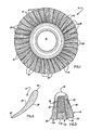
- a one-piece wheel 10 for use in a jet engine is illustrated in Fig. 1.
- the one-piece wheel 10 has a circular hub portion 12 and a plurality of radially outwardly projecting airfoils 14 disposed in a circular array about the periphery of the hub.
- Each of the airfoils 14 has a columnar grain crystalline structure with the longitudinal axes of the columnar grains extending generally parallel to the longitudinal central axes of the airfoils.
- the majority of the hub 12 has an equiaxed grain structure.
- the airfoils 14 are advantageously formed with a columnar grain crystalline structure, other known crystalline structures could be used if desired.
- Each of the airfoils 14 has a relatively thick leading edge portion 18 and a relatively thin trailing edge portion 20 (see Fig. 2).
- the leading and trailing edge portions 18 and 20 are interconnected by major side surfaces 24 and 26 of the airfoil 14. Since the overall configuration of the airfoil 14 is well known, it will not be further described herein in order to avoid prolixity of description.
- Each of the metal airfoils 14 has a columnar grain crystalline structure which has been indicated schematically in Figs. 1 and 3.
- the columnar grains extend from the radially outer tip end portions 30 of the airfoils inwardly to the root end portions 32 (Fig. 3).
- the columnar metal grains in each of the airfoils 14 have longitudinal central axes which extend generally parallel to the longitudinal central axes of the airfoils. Although it is preferred to form the airfoils 14 with a columnar grain structure in order to obtain the known advantages of this grain structure, other known crystalline structures could be provided if desired.
- the columnar grains in the airfoils 14 extend radially inwardly part the root end portion 32 of each of the airfoils a short distance into the hub 12. However, the majority of the hub 12 is formed with an equiaxed grain structure. Since the wheel 10 is cast as one piece, there are no joints between the airfoils 14 and the hub 12. This results in the one-piece wheel having a relatively strong construction.
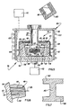
- the one-piece wheel 10 is cast in a ceramic mold 38 (see Fig. 4).
- the mold 38 has a circular main section 40 in which a wheel mold cavity 42 is formed.
- the mold cavity 42 has the same configuration as the one-piece wheel 10 of Fig. 1.
- the mold cavity 42 (Fig. 4) has a circular main or hub forming section 46 with the same configuration as the circular hub 12 of the wheel 10.
- a plurality of airfoil forming sections 48 extend radially outwardly from the circular main section 46 of the mold cavity 42.
- the airfoil forming sections 48 have the same configuration as the airfoils 14 of the one-piece wheel 10.
- the airfoil forming sections 48 could have outer end portions with a configuration which is different than the configuration of the tip end portions 30 of the airfoils 14. If this was done, the metal cast in the outer end portions of the airfoil forming sections 48 would be removed from the airfoils.
- the airfoil forming sections 48 have an open ended construction. Thus, a root end opening 52 is formed at a radially inner end portion of each of the airfoil forming sections 48 and a tip end opening 54 is formed at a radially outer end of the airfoil forming sections 48.
- the tip end openings 54 are disposed in a circular array in a circular outer side surface 58 of the main section 40 of the mold 38.
- the circular outer side surface 58 has the configuration of a frustrum of a cone.
- the airfoil forming sections 48 have longitudinally extending leading edge forming portions 62 and trailing edge forming portions 64.
- the leading and trailing edge forming portions 62 and 64 of each of the airfoil forming sections 48 extend between the outer side surface 58 and hub forming section 46 of the mold cavity 42. Due to the configuration of the airfoils 14 (see Fig. 2), the leading edge forming portions 62 of the airfoil forming sections 48 are thicker or wider than the trailing edge forming portions 64 of the airfoil forming sections.
- a generally cylindrical sprue 68 extends axially upwardly from the main portion 40 of the mold 38.
- the sprue 68 has a cylindrical central passage 70.
- the passage 70 is disposed in a coaxial relationship with the circular main section 46 and the circular array of airfoil forming sections 48.
- the mold 38 is advantageously formed by covering a wax pattern with ceramic mold material and then removing the pattern and firing the mold material.
- a wheel pattern section having the same configuration as the wheel 10 is formed of either natural or artificial wax. It may be preferred to form the hub pattern of wax and each airfoil pattern of plastic.
- a columnar sprue pattern section having the same configuration as the interior passage in the sprue 70 is formed of wax and connected with the wheel pattern.
- a rim pattern section is formed of wax and connected with the outer end portions of the airfoils of the wheel pattern.
- This rim pattern section may advantageously have a relatively thin radial section and a configuration corresponding to the frustum of a cone. This results in the rim pattern section having an appearance similar to the appearance of a lamp shade.
- a central portion of the inner side surface of the rim pattern section is connected with the outer ends of the wax airfoils of the wheel pattern.
- rim, wheel and sprue pattern sections have been interconnected, they are covered with a ceramic mold material.
- the circular upper and lower ends of the rim section are wiped as each layer of ceramic mold material is applied over the pattern. This separates the ceramic mold material overlying the radially outer portion of the rim from the remainder of the mold.
- the wax pattern material is removed by heating or using a suitable chemical solvent. Removing the wax pattern material and the ceramic material overlying the outer side surface of the rim exposes the outer side surface 58 of the mold and the circular array of openings 54.
- the circular outer side surface 58 of the mold 38 is shaped by the inner side surface of the rim pattern.
- the tip end openings 54 are shaped by the outer ends of the wax airfoil patterns.
- the ceramic mold material is then fired to form the mold 38.
- a chill 76 is used in order to obtain the desired crystalline structure of the airfoils 14.
- the chill 76 has a circular base or end wall 78.
- An upwardly projecting annular side wall 80 is fixedly connected to the end wall 78.
- the end wall, or ring section 78 and side wall 80 cooperate to define an open ended chill cavity 82. If desired, the end wall 78 could be omitted.
- the chill cavity 82 has a side surface 84 with a configuration corresponding to the frustrum of a cone.
- the conical inner side surface 84 extends from a flat circular side surface 86 of the end wall 78 of the chill to a circular opening 88 at the axially outer or upper end of the side wall 80.
- the inner side wall 84 of the chill cavity 82 has the same slope or taper as the outer side surface 58 of the main section 40 in the mold 38.
- the side surface 84 of the annular chill wall 80 and the side surface 58 of the mold 38 could axially taper at any desired angle between 5 and 20 degrees, it is preferred to use a taper of approximately 10 degrees.
- the chill cavity 82 has an axial extent which is greater than the axial extent of the main section 40 of the mold 38.
- passages 92 are formed in both the end wall 78 and annular side wall 80 to conduct cooling fluid.
- the walls 78 and 80 are formed of copper or brass.
- the passages 92 are formed in the end side walls 78 and 80 of the chill to conduct a flow of a cooling liquid during casting of the one-piece wheel 10. This cooling liquid will carry heat away from the chill 76 and prevent it from being damaged or destroyed by the molten metal from which the wheel 10 is formed.
- the mold 38 When a casting operation is to be undertaken, the mold 38 is preheated while it is spaced from the chill 76. Thus, during preheating, the mold 38 is disposed a substantial distance above the chill 76 in a high frequency induction furnace 96.
- the induction furnace 96 has a cylindrical graphite susceptor 98 which is circumscribed by turns of an induction coil 100.
- the induction coil 100 is formed in two separately energizable sections, that is an upper section 102 and a lower section 104.
- the mold 38 is preheated to a temperature which is above the melting point of the temperature of the metal to be poured.
- a drive assembly 110 is activated to move the mold 38 and furnace 96 downwardly toward the chill 76.
- a second drive assembly 112 is activated to raise the chill 76 upwardly toward the mold 38.
- a pair of drive assemblies 110 and 112 have been illustrated in Figs. 4 and 5 to move both the mold 38 and chill 76, it is contemplated that one of the drive assemblies could be omitted if desired.
- the drive assembly 110 could be omitted and only the drive assembly 112 used to raise and lower the chill 76 relative to the stationary furnace 96 and mold 38.
- the main section 40 of the mold moves through the circular opening 88 at the upper end of the annular chill section 80 and enters the chill cavity 82 (see Fig. 4).
- the mold 38 and chill 76 brings the conical outer side surface 58 on the mold into abutting engagement with the conical inner side surface 84 on the chill section 80 (see Fig. 5).
- the mold surface 58 is then disposed in tight abutting engagement with the chill surface 84.
- a circular lower surface 117 of the mold 38 is spaced from the end wall 78 of the chill when the mold surface 58 is disposed in tight abutting engagement with the chill surface 84.
- the chill surface 84 extends across each of the openings 54 at the ends of the airfoil forming sections 48.
- the open radially outer ends of the airfoil forming sections 48 are blocked by the annular chill 80 when the mold 38 and chill 76 have been brought into abutting engagement in the manner shown in Fig. 5.
- the chill surface 84 tightly seals the open outer end portions of the airfoil forming sections 48.
- Molten metal 118 is then poured from a melting furnace 120 into the mold 38.
- the molten metal 118 may have many different compositions, it is advantageously a nickel-chrome superalloy having a composition similar to that disclosed in US-A-3,260,505.
- metals having other known compositions could be used if desired.
- the molten metal is poured from the melting furnace 120 into the sprue 68.
- the molten metal flows axially downwardly through the sprue 68 into the main section 46 of the mold cavity 42.
- the molten metal then flows radially outwardly through the airfoil forming sections 48 to the side surface 84 of the annular chill 80.
- the mold 38 is maintained in tight abutting engagement with the annular chill 80 to prevent leakage of metal between the outer side surface 58 of the mold and the innder side surface 84 of the chill. If the angle at which the conical side surfaces 58 and 84 of the mold 38 and chill 76 are tapered at too large an angle from the vertical, hydrostatic pressure forces will tend to separate the mold and chill. Therefore, it is preferred to have the outer side surfaces 58 and 84 of the mold 38 and chill 76 tapered at an angle of approximately 10 degrees to the vertical.
- the molten metal flows to the openings 54 at the ends of the airfoil forming sections 48 and into engagement with the chill surface 84.
- Initial solidification of the molten metal at the chill surface 84 causes a plurality of grains to initially solidify in a growth zone close to the chill. The more favorably oriented grains quickly crowd out the less favorably oriented grains and grow away from the chill in a radially inward direction toward the center of the mold cavity 42. If desired, the molten metal which solidifies against the chill surface 84 may subsequently be removed from the airfoils.
- the solidified airfoils have an elongated columnar grain crystalline structure which is the same general crystalline structure as is described in US-A-3,417,809 and 3,485,291.
- the chill 76 could be used to initiate the formation of other known crystalline structures, such as the crystalline structures described in US-A-3,494,709; 3,542,120; and 4,133,368. Regardless of the crystalline structure, it may be desirable to remove the initial growth zone formed at the outer ends of the airfoil forming sections 48.
- the growth of elongated columnar grains in a direction generally parallel to the longitudinal central axes of the airfoil forming sections 48 is promoted by the strong cooling effect of the annular chill 80.
- This cooling effect is promoted by conducting a flow of cold liquid through the passages 92 formed in the annular mold section 80 and end wall 78 of the chill.
- the effectiveness of the chill is promoted by providing a layer 124 of insulation around the outside of the annular chill 80.
- the molten metal in the main section 46 of the mold cavity 42 begins to solidify.
- the metal in the sprue 68 remains molten to prevent the formation of shrink cavities in the main section 46 of the mold cavity 42.
- the lower section 104 of induction coil 100 may be shut off while the upper section 102 are maintained energized during the initial cooling of the molten metal in the airfoil forming sections 48.
- the current in the upper section 102 to the induction coil is reduced to promote a gradual solidification of the molten metal in the upper portion of the main section 46 of the mold cavity, and, subsequently, the sprue passage 70.
- the molten metal solidifies radially inwardly along fronts which extend generally perpendicular to the longitudinal central axes 125 (Fig. 6) of the airfoil forming sections.
- the leading edge portion 18 (Fig. 2) of each of the airfoils 14 is thicker than the trailing edge portion. Therefore, heat must be extracted at a greater rate from the lower portions 62 of the airfoil forming sections 48 where the leading edges 18 of the airfoils 14 are formed than from the upper portions 64 of the airfoil forming sections where the trailing edges 20 of the airfoils are formed.
- heat is extracted at a greater rate from the thick leading edge forming portions 62 than from the thin trailing edge forming portions 64.
- the greater rate of heat extraction from the leading edge forming portions 62 is obtained by having them disposed downwardly toward the end wall 78 of the chill 76.
- the thin trailing edge portions 64 are disposed upwardly toward the relatively hot furnace cavity.
- the rate at which heat is extracted from the leading edge forming portion 64 is modulated by placing a layer of insulation 128 over the circular bottom section 86 of the chill cavity 82.
- the extent to which the insulation 128 extends outwardly over the chill surface 86 and the thickness of this layer of insulation is determined to provide for solidification of the molten metal in the airfoil forming sections 48 along fronts which extend generally perpendicular to the longitudinal central axes of the airfoil forming sections 48. This results in the growth of the columnar grains of metal in directions parallel to the central axes of the airfoil forming sections 48.
- the metal While the metal is solidifying in the airfoil forming sections 48, the metal remains molten in the main section 46 of the mold cavity 42. This enables molten metal to flow from the main section 46 into the airfoil forming sections 48 to compensate for shrinkage of the metal as it solidifies.
- the layers 132 of insulation may be provided in the main section 40 of the mold immediately beneath the main section 46 to thereby retard the flow of heat from the main section 46 of the mold to the end wall 78 of the chill.
- maintaining the metal molten in the main section 46 of the mold cavity 42 is facilitated by energizing the upper coil section 102 during initial solidification of the metal in the airfoil forming sections 48.
- reinforcing sections 140 may be formed between upper and lower major sides 142 and 144 of the mold 38.
- the reinforcing sections 140 are formed by providing openings in the hub section of the wax pattern. Therefore, as the wax pattern is covered with ceramic mold material, the ceramic mold material enters these openings to form the reinforcing sections 140.
- the reinforcing sections 140 may be advantageously formed at spaced apart locations in the main section 46 of the mold cavity. Of course, the reinforcing sections 140 are positioned at locations where the forming of an opening through the central portion of the wheel 10 will not be objectionable.
- each of the airfoil forming sections 48 has an inner end 52 which opens into a central portion 46 of the mold and an outer end at an opening 54 in an outer side surface area of the mold.
- the mold and chill 76 are brought into engagement.
- the chill has a surface 84 which blocks the open outer ends 54 of the airfoil forming sections 48.
- molten metal is poured into the mold, it flows through the chill at the open outer ends 54 of the airfoil forming sections.
- the rapid removal of heat from the molten metal 38 by the chill 76 promotes the growth of columnar grains inwardly away from the chill, through the airfoil forming sections 48, to the central portion 46 of the mold.
- Heat is transferred from the relatively thick leading edge portions 62 of the airfoil forming sections 48 to the chill 76 at a greater rate than from the relatively thin trailing edge portions 64 of the airfoil forming sections.
- This promotes, solidification of the molten metal in the airfoil forming sections 48 along fronts which extend generally perpendicular to the longitudinal central axes 125 of the airfoils.
- this promotes the growth of columnar crystals having longitudinal axes which extend parallel to the central axes 125 of the airfoils.
Landscapes
- Engineering & Computer Science (AREA)
- Mechanical Engineering (AREA)
- Molds, Cores, And Manufacturing Methods Thereof (AREA)
- Turbine Rotor Nozzle Sealing (AREA)
Claims (14)
Applications Claiming Priority (2)
| Application Number | Priority Date | Filing Date | Title |
|---|---|---|---|
| US07/413,835 US4850419A (en) | 1982-09-01 | 1982-09-01 | Method of casting a one-piece wheel |
| US413835 | 1982-09-01 |
Publications (2)
| Publication Number | Publication Date |
|---|---|
| EP0104794A1 EP0104794A1 (de) | 1984-04-04 |
| EP0104794B1 true EP0104794B1 (de) | 1987-07-22 |
Family
ID=23638851
Family Applications (1)
| Application Number | Title | Priority Date | Filing Date |
|---|---|---|---|
| EP83305027A Expired EP0104794B1 (de) | 1982-09-01 | 1983-08-31 | Verfahren zum Giessen eines einstückigen Rades |
Country Status (6)
| Country | Link |
|---|---|
| US (1) | US4850419A (de) |
| EP (1) | EP0104794B1 (de) |
| JP (1) | JPS5964151A (de) |
| CA (1) | CA1232740A (de) |
| DE (1) | DE3372591D1 (de) |
| IL (1) | IL69589A0 (de) |
Families Citing this family (11)
| Publication number | Priority date | Publication date | Assignee | Title |
|---|---|---|---|---|
| US4813470A (en) * | 1987-11-05 | 1989-03-21 | Allied-Signal Inc. | Casting turbine components with integral airfoils |
| US5072771A (en) * | 1988-03-28 | 1991-12-17 | Pcc Airfoils, Inc. | Method and apparatus for casting a metal article |
| EP0506608B1 (de) * | 1991-03-26 | 1996-12-27 | Sulzer Innotec Ag | Vorrichtung zur Herstellung von gerichtet erstarrten Gussstücken |
| US5931214A (en) * | 1997-08-07 | 1999-08-03 | Howmet Research Corporation | Mold heating vacuum casting furnace |
| US6443215B1 (en) * | 1998-12-31 | 2002-09-03 | Hayes Lemmerz International, Inc. | Vehicle wheel mold with a retractable ball cap |
| RU2265497C1 (ru) * | 2004-05-24 | 2005-12-10 | Федеральное государственное унитарное предприятие "Всероссийский научно-исследовательский институт авиационных материалов" (ФГУП "ВИАМ") | Способ получения элемента рабочего колеса турбины и рабочего колеса турбины |
| US20090301682A1 (en) * | 2008-06-05 | 2009-12-10 | Baker Hughes Incorporated | Casting furnace method and apparatus |
| US9278389B2 (en) * | 2011-12-20 | 2016-03-08 | General Electric Company | Induction stirred, ultrasonically modified investment castings and apparatus for producing |
| WO2015020715A2 (en) | 2013-06-17 | 2015-02-12 | United Technologies Corporation | Gas turbine hub |
| WO2017063993A1 (en) * | 2015-10-14 | 2017-04-20 | Aleris Rolled Products Germany Gmbh | Method and device for casting metal alloy ingots |
| CN112387957A (zh) * | 2020-11-17 | 2021-02-23 | 潘毅冰 | 一种用于铝合金汽车轮毂生产的清洁型铸造装置 |
Family Cites Families (12)
| Publication number | Priority date | Publication date | Assignee | Title |
|---|---|---|---|---|
| US1015362A (en) * | 1911-01-24 | 1912-01-23 | Griffin Wheel Co | Car-wheel mold and method of making car-wheels. |
| US3283377A (en) * | 1964-06-29 | 1966-11-08 | Trw Inc | Turbine wheel manufacturing method |
| US3312449A (en) * | 1964-06-29 | 1967-04-04 | Trw Inc | Turbine wheel |
| US3417809A (en) * | 1965-07-16 | 1968-12-24 | United Aircraft Corp | Method of casting directionally solidified articles |
| US3538981A (en) * | 1968-08-05 | 1970-11-10 | United Aircraft Corp | Apparatus for casting directionally solidified articles |
| US3598169A (en) * | 1969-03-13 | 1971-08-10 | United Aircraft Corp | Method and apparatus for casting directionally solidified discs and the like |
| US3680625A (en) * | 1970-11-12 | 1972-08-01 | Trw Inc | Heat reflector |
| US3754592A (en) * | 1972-02-15 | 1973-08-28 | Gen Motors Corp | Method for producing directionally solidified cast alloy articles |
| FR2319445A1 (fr) * | 1975-08-01 | 1977-02-25 | Codari Dubru | Procede et dispositif pour la coulee de pieces metalliques circulaires |
| US4152816A (en) * | 1977-06-06 | 1979-05-08 | General Motors Corporation | Method of manufacturing a hybrid turbine rotor |
| JPS5465125A (en) * | 1977-11-02 | 1979-05-25 | Toyoda Chuo Kenkyusho Kk | Cating metal mold |
| US4240495A (en) * | 1978-04-17 | 1980-12-23 | General Motors Corporation | Method of making cast metal turbine wheel with integral radial columnar grain blades and equiaxed grain disc |
-
1982
- 1982-09-01 US US07/413,835 patent/US4850419A/en not_active Expired - Fee Related
-
1983
- 1983-08-29 CA CA000435550A patent/CA1232740A/en not_active Expired
- 1983-08-29 IL IL69589A patent/IL69589A0/xx unknown
- 1983-08-31 EP EP83305027A patent/EP0104794B1/de not_active Expired
- 1983-08-31 DE DE8383305027T patent/DE3372591D1/de not_active Expired
- 1983-09-01 JP JP58161188A patent/JPS5964151A/ja active Granted
Also Published As
| Publication number | Publication date |
|---|---|
| DE3372591D1 (en) | 1987-08-27 |
| JPS5964151A (ja) | 1984-04-12 |
| US4850419A (en) | 1989-07-25 |
| EP0104794A1 (de) | 1984-04-04 |
| CA1232740A (en) | 1988-02-16 |
| JPS6349590B2 (de) | 1988-10-05 |
| IL69589A0 (en) | 1983-11-30 |
Similar Documents
| Publication | Publication Date | Title |
|---|---|---|
| EP0398895B1 (de) | Giessen von turbinenteilen mit integrierten schaufeln | |
| US4728258A (en) | Turbine engine component and method of making the same | |
| DE69813968T2 (de) | Vakuum-Giessofen mit Kokillenheizung | |
| EP0104794B1 (de) | Verfahren zum Giessen eines einstückigen Rades | |
| US4987944A (en) | Method of making a turbine engine component | |
| EP3027340B1 (de) | Gussformen und herstellungsverfahren | |
| EP2496374B1 (de) | Herstellungsverfahren für einteilige objekte | |
| US5069265A (en) | Method of making a turbine engine component | |
| US8752609B2 (en) | One-piece manufacturing process | |
| US4724891A (en) | Thin wall casting | |
| EP2025434A1 (de) | Vorgeformte keramische Keimhalterung für einen Monokristallstarterkeim | |
| JPS6129916B2 (de) | ||
| US5181550A (en) | Method of making a turbine engine component | |
| EP0747150B1 (de) | Verfahren und Vorrichtung zur gerichtete Erstarrung von Teilen mit integrierten Elementen | |
| US4905752A (en) | Method of casting a metal article | |
| KR100388509B1 (ko) | 바이메탈연마휠의제조방법및그에의해얻어진연삭휠 | |
| US20140110077A1 (en) | Casting Process and Apparatus | |
| JPH08511995A (ja) | 金属物品の鋳造方法 | |
| US4809764A (en) | Method of casting a metal article | |
| US4730657A (en) | Method of making a mold | |
| GB2259660A (en) | A mould for casting components | |
| CA1196470A (en) | Method of reducing casting time | |
| GB2106021A (en) | Apparatus and method for producing a metal casting which contains a recess |
Legal Events
| Date | Code | Title | Description |
|---|---|---|---|
| PUAI | Public reference made under article 153(3) epc to a published international application that has entered the european phase |
Free format text: ORIGINAL CODE: 0009012 |
|
| AK | Designated contracting states |
Designated state(s): BE CH DE FR GB IT LI SE |
|
| 17P | Request for examination filed |
Effective date: 19840604 |
|
| ITF | It: translation for a ep patent filed | ||
| RAP1 | Party data changed (applicant data changed or rights of an application transferred) |
Owner name: PCC AIRFOILS, INC |
|
| GRAA | (expected) grant |
Free format text: ORIGINAL CODE: 0009210 |
|
| AK | Designated contracting states |
Kind code of ref document: B1 Designated state(s): BE CH DE FR GB IT LI SE |
|
| REF | Corresponds to: |
Ref document number: 3372591 Country of ref document: DE Date of ref document: 19870827 |
|
| ET | Fr: translation filed | ||
| PLBE | No opposition filed within time limit |
Free format text: ORIGINAL CODE: 0009261 |
|
| STAA | Information on the status of an ep patent application or granted ep patent |
Free format text: STATUS: NO OPPOSITION FILED WITHIN TIME LIMIT |
|
| 26N | No opposition filed | ||
| PG25 | Lapsed in a contracting state [announced via postgrant information from national office to epo] |
Ref country code: LI Effective date: 19880831 Ref country code: CH Effective date: 19880831 |
|
| PG25 | Lapsed in a contracting state [announced via postgrant information from national office to epo] |
Ref country code: SE Effective date: 19880901 |
|
| REG | Reference to a national code |
Ref country code: CH Ref legal event code: PL |
|
| PGFP | Annual fee paid to national office [announced via postgrant information from national office to epo] |
Ref country code: GB Payment date: 19900713 Year of fee payment: 8 |
|
| PGFP | Annual fee paid to national office [announced via postgrant information from national office to epo] |
Ref country code: FR Payment date: 19900822 Year of fee payment: 8 |
|
| PGFP | Annual fee paid to national office [announced via postgrant information from national office to epo] |
Ref country code: DE Payment date: 19900828 Year of fee payment: 8 |
|
| PGFP | Annual fee paid to national office [announced via postgrant information from national office to epo] |
Ref country code: BE Payment date: 19901213 Year of fee payment: 8 |
|
| PG25 | Lapsed in a contracting state [announced via postgrant information from national office to epo] |
Ref country code: GB Effective date: 19910831 Ref country code: BE Effective date: 19910831 |
|
| BERE | Be: lapsed |
Owner name: PCC AIRFOILS INC Effective date: 19910831 |
|
| GBPC | Gb: european patent ceased through non-payment of renewal fee | ||
| PG25 | Lapsed in a contracting state [announced via postgrant information from national office to epo] |
Ref country code: FR Effective date: 19920430 |
|
| PG25 | Lapsed in a contracting state [announced via postgrant information from national office to epo] |
Ref country code: DE Effective date: 19920501 |
|
| REG | Reference to a national code |
Ref country code: FR Ref legal event code: ST |
|
| EUG | Se: european patent has lapsed |
Ref document number: 83305027.1 Effective date: 19890712 |