EP0242811A2 - Table and/or cupboard to be put up against a vertical wall - Google Patents
Table and/or cupboard to be put up against a vertical wall Download PDFInfo
- Publication number
- EP0242811A2 EP0242811A2 EP87105688A EP87105688A EP0242811A2 EP 0242811 A2 EP0242811 A2 EP 0242811A2 EP 87105688 A EP87105688 A EP 87105688A EP 87105688 A EP87105688 A EP 87105688A EP 0242811 A2 EP0242811 A2 EP 0242811A2
- Authority
- EP
- European Patent Office
- Prior art keywords
- guide
- wall
- base plate
- plate
- cabinet
- Prior art date
- Legal status (The legal status is an assumption and is not a legal conclusion. Google has not performed a legal analysis and makes no representation as to the accuracy of the status listed.)
- Granted
Links
Images


Classifications
-
- A—HUMAN NECESSITIES
- A47—FURNITURE; DOMESTIC ARTICLES OR APPLIANCES; COFFEE MILLS; SPICE MILLS; SUCTION CLEANERS IN GENERAL
- A47B—TABLES; DESKS; OFFICE FURNITURE; CABINETS; DRAWERS; GENERAL DETAILS OF FURNITURE
- A47B9/00—Tables with tops of variable height
- A47B9/10—Tables with tops of variable height with vertically-acting fluid cylinder
-
- A—HUMAN NECESSITIES
- A47—FURNITURE; DOMESTIC ARTICLES OR APPLIANCES; COFFEE MILLS; SPICE MILLS; SUCTION CLEANERS IN GENERAL
- A47B—TABLES; DESKS; OFFICE FURNITURE; CABINETS; DRAWERS; GENERAL DETAILS OF FURNITURE
- A47B17/00—Writing-tables
- A47B17/02—Writing-tables with vertically-adjustable parts
-
- A—HUMAN NECESSITIES
- A47—FURNITURE; DOMESTIC ARTICLES OR APPLIANCES; COFFEE MILLS; SPICE MILLS; SUCTION CLEANERS IN GENERAL
- A47B—TABLES; DESKS; OFFICE FURNITURE; CABINETS; DRAWERS; GENERAL DETAILS OF FURNITURE
- A47B51/00—Cabinets with means for moving compartments up and down
-
- A—HUMAN NECESSITIES
- A47—FURNITURE; DOMESTIC ARTICLES OR APPLIANCES; COFFEE MILLS; SPICE MILLS; SUCTION CLEANERS IN GENERAL
- A47B—TABLES; DESKS; OFFICE FURNITURE; CABINETS; DRAWERS; GENERAL DETAILS OF FURNITURE
- A47B77/00—Kitchen cabinets
- A47B77/04—Provision for particular uses of compartments or other parts ; Compartments moving up and down, revolving parts
- A47B77/10—Provision for particular uses of compartments or other parts ; Compartments moving up and down, revolving parts with members movable outwards to a position of use, e.g. tables, ironing boards
-
- A—HUMAN NECESSITIES
- A47—FURNITURE; DOMESTIC ARTICLES OR APPLIANCES; COFFEE MILLS; SPICE MILLS; SUCTION CLEANERS IN GENERAL
- A47B—TABLES; DESKS; OFFICE FURNITURE; CABINETS; DRAWERS; GENERAL DETAILS OF FURNITURE
- A47B9/00—Tables with tops of variable height
- A47B9/12—Tables with tops of variable height with flexible height-adjusting means, e.g. rope, chain
Definitions
- the invention relates to a cabinet and / or table furniture that can be mounted on a vertical wall, the positions of which can be changed on the wall, such that one or more wall cabinets arranged next to one another each have an upper end position close to the wall and a lower end position remote from the wall and / or one or more Tables arranged next to one another can be adjusted between an upper and a lower end position parallel to the mounting wall and can be locked in any position within the movement path.
- Tables and chairs are already known, the position of which can be changed in height and can be determined at any height within the range of mobility.
- Such furniture is usually one with a central column in which a spring mechanism for height adjustment is arranged.
- crank mechanisms are also generally known for tables, the height of the table top being changeable by actuating a crank.
- Such crank mechanisms are particularly well known in four-legged tables, in which the legs are at least partially telescopic and their length can be changed by the crank mechanism.
- DE-G 86 09 441.6 has also already made known a height adjustment for furniture, in particular for wall cupboards, in which a winding shaft in the form of a tube, which is already known in roller shutter construction, is used with a tubular motor arranged in such a way that it cannot rotate.
- the drive is connected to a frame supporting the furniture part, the Drive having axially spaced gears, which are rotatably mounted in the frame and engage in a toothed belt which is fixed in position and vertically in the frame.
- the height adjustment device according to DE-G 86 09 441.6 also has disadvantages.
- this device is not suitable for moving wall cabinets between an upper position close to the wall and a lower position away from the wall without special supporting and guiding elements for the cabinet or the cabinets being required for this.
- the invention is therefore based on the object of designing a cupboard and / or table furniture of the type defined at the outset in such a way that a plurality of furniture parts arranged next to one another can be moved by an adjusting device between the end points of a movement path and can be held safely and for any length of time within the movement path in any position.
- the position adjustments should be able to be carried out easily and without risk of accidents even by disabled people without any significant effort and skill.
- a table furniture according to the invention does not always have to be designed as a wall table.
- Various embodiments of a free-standing table are also possible, as is evident from claim 14.
- Claims 15 and 16 show an alternative solution for the electrically driven device for lifting and lowering the furniture parts arranged on a base plate and for guiding the wall cabinets.
- a base plate 2 is fastened to a vertical wall 1, on which a plurality of wall cabinets 3 connected to one another are juxtaposed between an upper rear wall End position and a lower end position remote from the rear wall are arranged so that they can be held in any position on this movement path.
- a plurality of tables 4 arranged next to one another and connected to one another, with a support plate 4a provided near the rear edge of the table between an upper and a lower end position. They can also be held in any position on this route.
- a pair of guide plates 5 flanking the outer side walls 3a of the wall cabinets 3 are fastened to the base plate 2.
- the side walls 3a of the wall cabinets 3 each have a bore 6 in their upper area near the rear wall, in which a tubular shaft 7, which is guided transversely through the wall cabinets 3 and with a tubular motor arranged in a manner such that it cannot rotate, can be rotated.
- a bearing 8 is secured against rotation by means of a flange collar 8a, in which the tubular shaft 7 is mounted. With these bearings 8, the wall cabinets 3 are carried on the tubular shaft 7. If several wall cabinets 3 are arranged next to one another, the bore 6 for the tubular shaft 7 can also be provided with an intermediate bearing enclosing this for at least one inner side wall 3a of a wall cabinet 3.
- the ends of the tubular shaft 7 are each non-positively connected outside the wall cabinets 3 with a drive and guide element which extends in the direction of movement of the wall cabinets 3 and extends over the entire movement distance Has guide path and in turn is attached to the adjacent side wall 3a of a wall cabinet 3 flanking guide plate 5.
- the drive and guide elements for the tables each have a rectangular-C-shaped guide profile 9, which is fastened in connection with wall cabinets 3 with its wide profile side (rear) to the inside of the guide plate 5 in question in the direction of movement of the wall cabinets 3.
- an elongated bearing plate 10 is arranged to be movable in the longitudinal direction, the length of which is as much shorter than the guide profile 9 as the movement distance of the wall cabinets.
- the tubular shaft 7 is rotatably mounted with a bearing pin 11 and a chain drive wheel 12 secured against rotation.
- two guide rollers 13, 14, 15, 16 are rotatably mounted laterally on the bearing plate 10, axially parallel to the tubular shaft 9, with which the latter is guided in a supporting manner on the two narrow sides of the guide profile 9.
- a drive chain 17 running in the longitudinal direction next to the bearing plate 10 on the side of the chain drive wheel 12 and in engagement therewith under tension with its two ends on the wall of the guide profile 9.
- abutments 18, 19 are provided at both ends of the guide profile 9, each of which is penetrated by a screw 20, 21 holding one end of the drive chain 17 and serve as nuts 20a, 21a screwed onto the screw ends.
- a chain tensioner 22 At one end of the drive chain 17 there is a chain tensioner 22 in the form of a package of disc springs which are located on the screw 20 outside the abutment 18 arranged and tensioned by the nut 20a.
- the two guide rollers 13, 14 provided on the drive chain-side long side of the bearing plate 10 are arranged on the surface of the bearing plate 10 opposite the drive chain 17, while the guide rollers 15, 16 provided on the other long side of the bearing plate 10 are arranged on the surface of the bearing plate facing the tubular shaft 7 are arranged.
- a chain deflection wheel 24, 25, which engages with the drive chain 17, is mounted, as a result of which the chain drive wheel 12 is in engagement with the drive chain 17 over a larger part of its circumference.
- the bearing plates 10 are each attached to the relevant side wall 3a of a wall cabinet via a plurality of spacers 10a, while the broad side of the guide profile 9 is fastened to the inside of the relevant guide plate 5.
- the longitudinal axis of the support rail 26 in the plane of its leg connected to the bearing plate 10 can be inclined against the longitudinal axis of the bearing plate 10 about a pivot axis 27 near its one end and can be determined in any inclination within certain limits.
- the support rail 26 has, near its end opposite the pivot axis 27, an elongated hole 28, in which an eccentric 29 can be rotated.
- the length of the tubular shaft 7 is approximately half as long as the total width of the tables 4, being perpendicular to the A known rail and roller guide 33 is arranged on each of the two tube shaft ends.
- This consists in each case of a profile rail 33a fastened to the base plate 2 with an essentially U-shaped cross section and inwardly angled profile leg edges, in which a plurality of roller sets 33b fastened to the carrier plate 4a of the table in question 4 are guided. This gives the tables additional supportive guidance, which increases the load capacity of the tables.
- the drive and guide elements for the wall cabinets 3 differ for those for the tables 4 in that two spacers 10a are provided on the bearing plate 10 instead of a support rail -26, via which the bearing plate 10 is fixedly connected to a side wall 3a of a wall cabinet. Furthermore, the ends of the guide rail 9 are chamfered according to their oblique arrangement and the guide rollers are placed differently on the bearing plate 10 due to the chamfered guide rail ends. Finally, the guide slider 23 can also be dispensed with here.
- FIG. 9 shows a further exemplary embodiment of the invention in the form of a free-standing desk.
- the base plate 2 is held free-standing by two foot elements in the form of angles 2a made of square tubular steel. One leg of each of these angles 2a is fastened vertically to the inside of the base plate 2, while the other leg is supported horizontally below the table on the floor 1a.
- a vertically downwardly extending cover plate 34 which extends over the base plate and extends so far that its lower edge, with the highest possible setting of the table furniture, still lies above or at the same height as the upper edge of the base plate 2 is located.
- the table has vertical side walls, the rear edges of which are each connected to a side edge of the cover plate 34 and extend at least below the lower edge of the support plate 4a.
- the desk is equipped at least on one side with drawers 35 in a manner known per se.
Landscapes
- Combinations Of Kitchen Furniture (AREA)
- Tables And Desks Characterized By Structural Shape (AREA)
Abstract
Die Erfindung betrifft ein an einer senkrechten Wand montierbares Schrank- und/oder Tischmöbel, dessen Positionen an einer Wand veränderbar sind, derart, daß ein oder mehrere nebeneinander angeordnete Hängeschränke jeweils zwischen einer oberen wandnahen Endlage und einer unteren wandfernen Endlage und/oderein oder mehrere nebeneinander angeordnete Tische zwischen einer oberen und einer unteren Endlage parallel zur Montagewand verstellbar und innerhalb der Bewegungsstrecke in jeder beliebigen Position feststellbar sind. Die Erfindung besteht im wesentlichen darin, daß wenigstens eine in senkrechter Ebene fixierbare Basisplatte (2) mit wenigstens einer Führungseinrichtung für wenigstens ein daran in der Höhe verstellbares Möbelteil (3, 4) ausgestattet ist. Die Führungseinrichtung hat wenigstens eine Paar Führungselemente, die einerseits mit der Basisplatte (2) verbunden sind und andererseits die Möbelteile tragen und in der gewünschten Richtung führen, wobei jedes Führungselement an einer senkrecht an der Basisplatte (2) rechtwinklig zu dieser befestigten, eine Seitenwand (3a) eines Hängeschrankes (3) flankierenden Führungsplatte (5) angeordnet ist.The invention relates to a cabinet and / or table furniture that can be mounted on a vertical wall, the positions of which can be changed on a wall, such that one or more wall cabinets arranged next to one another each have an upper end position close to the wall and a lower end position remote from the wall and / or one or more side by side arranged tables between an upper and a lower end position parallel to the mounting wall and adjustable within the movement distance in any position. The invention essentially consists in that at least one base plate (2) which can be fixed in the vertical plane is equipped with at least one guide device for at least one height-adjustable furniture part (3, 4). The guide device has at least one pair of guide elements which are connected on the one hand to the base plate (2) and on the other hand carry the furniture parts and guide them in the desired direction, each guide element being attached to a side wall on a base plate (2) perpendicular to the base plate (2). 3a) of a wall cabinet (3) flanking guide plate (5) is arranged.
Jeder Tisch (4) hat an oder nahe seiner basisplattenseitigen Kante eine senkrechte Trägerplatte (4a). Die Bauteile der Führungseinrichtung für den oder die Tische sind einerseits an der Basisplatte (2) und andererseits an der Trägerplatte (4a) befestigt. Jedes an der Basisplatte (2) angeordnete Möbelteil (3, 4) ist über eine elektrisch angetriebene Vorrichtung zum Heben und Senken der Möbelteile kraftschlüssig mit der Basisplatte (2) verbunden.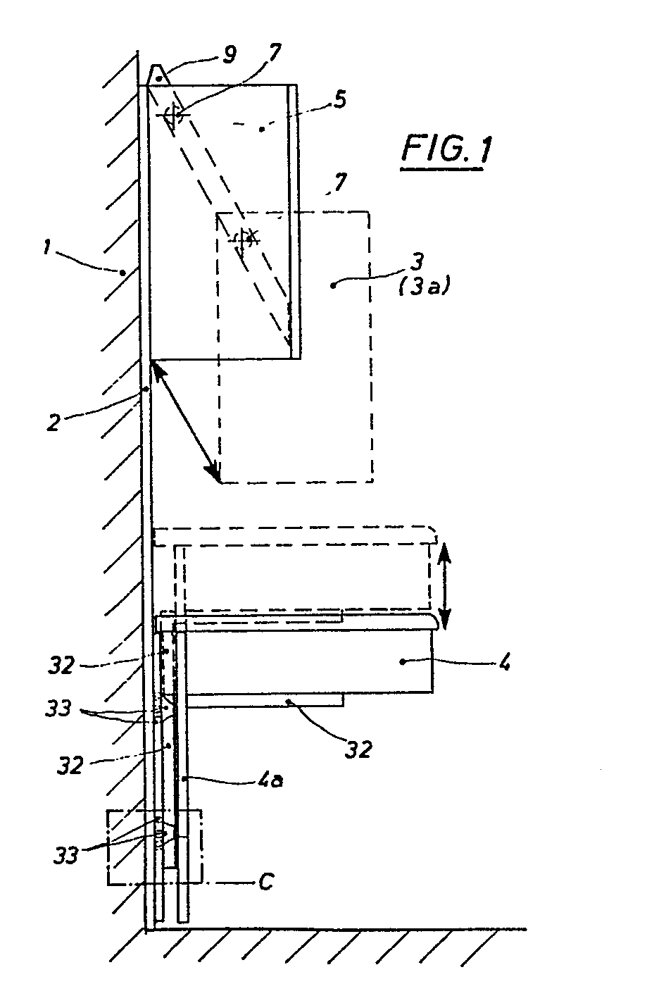
Description
Die Erfindung betrifft ein an einer senkrechten Wand montierbares Schrank- und/oder Tischmöbel, dessen Positionen an der Wand veränderbar sind, derart, daß ein oder mehrere nebeneinander angeordnete Hängeschränke jeweils zwischen einer oberen wandnahen Endlage und einer unteren wandfernen Endlage und/oder ein oder mehrere nebeneinander angeordnete Tische zwischen einer oberen und einer unteren Endlage parallel zur Montagewand verstellbar und innerhalb der Bewegungsstrecke in jeder beliebigen Position feststellbar sind.The invention relates to a cabinet and / or table furniture that can be mounted on a vertical wall, the positions of which can be changed on the wall, such that one or more wall cabinets arranged next to one another each have an upper end position close to the wall and a lower end position remote from the wall and / or one or more Tables arranged next to one another can be adjusted between an upper and a lower end position parallel to the mounting wall and can be locked in any position within the movement path.
Es sind bereits Tische und Stühle bekannt, deren Benutzungsposition in der Höhe veränderbar und innerhalb der Beweglichkeitsstrecke in jeder beliebigen Höhe feststellbar ist. Bei derartigen Möbeln handelt es sich meist um solche mit einer Mittelsäule, in der ein Federmechanismus zur Höhenverstellung angeordnet ist.Tables and chairs are already known, the position of which can be changed in height and can be determined at any height within the range of mobility. Such furniture is usually one with a central column in which a spring mechanism for height adjustment is arranged.
Zur Absenkung der Benutzungsfläche wird durch Anheben eines unter der Tischfläche bzw. unter dem Stuhlsitz angeordneten Arretierungshebels der Federmechanismus entriegelt, wonach sich die Tischplatte bzw. der Stuhlsitz durch den Federmechanismus selbsttätig hebt oder manuell bis in die gewünschte Höhe niedergedrückt werden kann. Durch Niederdrücken des Arretierungshebels wird der Federmechanismus in der betreffenden Position fixiert.To lower the area of use, the spring mechanism is unlocked by lifting a locking lever located under the table surface or under the chair seat, after which the table top or the chair seat is raised automatically by the spring mechanism or can be pushed down manually to the desired height. The spring mechanism is fixed in the relevant position by depressing the locking lever.
Bei Tischen sind auch Kurbelmechanismen allgemein bekannt, wobei durch Betätigung einer Kurbel die Höhe der Tischplatte veränderbar ist. Solche Kurbelmechanismen sind insbesondere bei vierbeinigen Tischen allgemein bekannt, bei denen die Beine wenigstens teilweise teleskopartig ausgebildet und ihre Länge durch den Kurbeltrieb veränderbar ist.Crank mechanisms are also generally known for tables, the height of the table top being changeable by actuating a crank. Such crank mechanisms are particularly well known in four-legged tables, in which the legs are at least partially telescopic and their length can be changed by the crank mechanism.
Für die meisten bewegungsbehinderten Personen sind die vorstehend beschriebenen allgemein bekannten Vorrichtungen zur Höhenverstellung insbesondere bei Tischen nicht geeignet, da ein nicht unerheblicher Kraftaufwand zum Niederdrücken der Tischplatte gegen die Wirkung des Federmechsnismus erforderlich ist. Ein solcher Kraftaufwand ist von bewegungsbehinderten, zumal in einem Rollstuhl sitzenden Personen kaum zu leisten. Das trifft auch auf Verstelleinrichtungen mit Kurbelmechanismus zu.For most people with reduced mobility, the generally known devices for height adjustment described above are not suitable, in particular for tables, since a not inconsiderable expenditure of force is required to depress the tabletop against the action of the spring mechanism. Such an effort is hardly achievable by people with reduced mobility, especially since people sitting in a wheelchair. This also applies to adjustment devices with a crank mechanism.
Durch das DE-G 86 09 441.6 ist auch bereits eine Höhenverstellung für Möbel, insbesondere für Hängeschränke bekannt geworden, bei der eine im Rolladenbau schon vorher bekannte Wickelwelle in Form eines Rohres mit einem darin verdrehsicher angeordneten Rohrmotor verwendet wird. Hierbei ist der Antrieb mit einem das Möbelteil tragenden Gestell verbunden, wobei der Antrieb mit axialem Abstand voneinander angeordnete Zahnräder aufweist, die im Gestell drehbar gelagert sind und in einen hinsichtlich Höhenlage ortsfest und senkrecht im Gestell angeordneten Zahnriemen eingreifen.DE-G 86 09 441.6 has also already made known a height adjustment for furniture, in particular for wall cupboards, in which a winding shaft in the form of a tube, which is already known in roller shutter construction, is used with a tubular motor arranged in such a way that it cannot rotate. Here, the drive is connected to a frame supporting the furniture part, the Drive having axially spaced gears, which are rotatably mounted in the frame and engage in a toothed belt which is fixed in position and vertically in the frame.
In der genannten Gebrauchsmusterschrift wird vorgeschlagen, am Gestell und/oder am Möbelteil Führungselemente vorzusehen, die mit ortsfesten, z.B. an einer Raumwand anzubringenden Führungsschienen in Eingriff stehen, damit die mit der Höhenverstellvorrichtung ausgerichteten Möbel sicher geführt sind.In the mentioned utility model specification it is proposed to provide guide elements on the frame and / or on the furniture part, which are fixed with stationary, e.g. guide rails to be attached to a room wall so that the furniture aligned with the height adjustment device is guided securely.
Die Höhenverstellvorrichtung nach dem DE-G 86 09 441.6 weist jedoch ebenfalls Nachteile auf. Insbesondere ist diese Vorrichtung nicht geeignet, Wandschränke zwischen einer oberen wandnahen und einer unteren wandfernen Position zu bewegen, ohne daß hierfür noch besondere Trag- und Führungselemente für den Schrank bzw. die Schränke erforderlich wären.However, the height adjustment device according to DE-G 86 09 441.6 also has disadvantages. In particular, this device is not suitable for moving wall cabinets between an upper position close to the wall and a lower position away from the wall without special supporting and guiding elements for the cabinet or the cabinets being required for this.
Zahnriemen, deren Zähne bekanntlich aus elastischem Material bestehen, können auch einer Dauerbelastung, wie sie sich durch das ständige Tragen des gesamten Gewichts der gefüllten Schränke z.B. in einer oberen Endlage auf längere Zeit ergibt, nicht standhalten. Wenn nicht zusätzliche, in der jeweils gewünschten Position in Eingriff bringbare Halteelemente vorgesehen sind, werden sich die Zähne der Zahnriemen im Laufe der Zeit verformen, so daß ein einwandfreier Eingriff in die Zahnräder nicht mehr gewährleistet ist. Es kann infolgedessen zu Unfällen kommen.Timing belts, the teeth of which are known to be made of elastic material, can also withstand a permanent load, such as is caused by the constant carrying of the entire weight of the filled cabinets in an upper end position for a long time, do not withstand. If additional holding elements that can be brought into engagement in the respectively desired position are not provided, the teeth of the toothed belt will deform over time, so that a perfect engagement in the gearwheels is no longer guaranteed. As a result, accidents can occur.
Der Erfindung liegt daher die Aufgabe zugrunde, ein Schrank- und/oder Tischmöbel der eingangs definierten Gattung so zu gestalten, daß mehrere nebeneinander angeordnete Möbelteile durch eine Verstellvorrichtung zwischen den Endpunkten einer Bewegungsbahn bewegbar und innerhalb der Bewegungsstrecke in jeder beliebigen Position sicher und beliebig lange gehalten werden können. Die Positionsverstellungen sollen ohne nennenswerten Aufwand an Kraft und Geschicklichkeit auch von behinderten Personen leicht und ohne Unfallgefahr vorgenommen werden können.The invention is therefore based on the object of designing a cupboard and / or table furniture of the type defined at the outset in such a way that a plurality of furniture parts arranged next to one another can be moved by an adjusting device between the end points of a movement path and can be held safely and for any length of time within the movement path in any position. The position adjustments should be able to be carried out easily and without risk of accidents even by disabled people without any significant effort and skill.
Zur Lösung dieser Aufgabe geht die Erfindung aus von einem an einer senkrechten Wand montierbaren Schrank-und/oder Tischmöbel, dessen Positionen an der Wand veränderbar sind, derart, daß ein oder mehrere nebeneinander angeordnete Hängeschränke jeweils zwischen einer oberen wandnahen Endlage und einer unteren wandfernen Endlage und/oder ein oder mehrere nebeneinander angeordnete Tische zwischen einer oberen und einer unteren Endlage parallel zur Montagewand verstellbar und innerhalb der Bewegungsstrecke in jeder beliebigen Position feststellbar sind.To achieve this object, the invention is based on a cabinet and / or table furniture which can be mounted on a vertical wall and the positions of which can be changed on the wall, such that one or more wall cabinets arranged next to one another each have an upper end position close to the wall and a lower end position remote from the wall and / or one or more tables arranged next to one another are adjustable between an upper and a lower end position parallel to the mounting wall and can be locked in any position within the movement path.
Die gestellte Aufgabe wird erfindungsgemäß wenigstens in ihren Grundzügen bereits dadurch gelöst,
- daß wenigstens eine in senkrechter Ebene fixierbare Basisplatte mit wenigstens einer Führungseinrichtung für wenigstens ein daran in der Höhe verstellbares Möbelteil ausgestattet ist;
- daß die Führungseinrichtung bzw. -einrichtungen für einen oder mehrere nebeneinander angeordnete Hängeschränke wenigstens ein Paar Führungselemente hat, die einerseits mit der Basisplatte verbunden sind und andererseits den bzw. die Hängeschränke zwischen einer oberen montagewandnahen Endlage und einer unteren montagewandfernen Endlage beweglich tragen und führen, wobei jedes Führungselement in einer senkrecht an der Basisplatte rechtwinklig zu dieser befestigten, eine Seitenwand eines Hängeschrankes flankierenden Führungsplatte angeordnet ist;
- daß die Führungseinrichtung für einen oder mehrere nebeneinander angeordnete Tische wenigstens zwei an sich bekannte Führungsschienen- und Rollensätze aufweist, die einerseits parallel zueinander senkrecht an der Basisplatte befestigt sind und andererseits den bzw. die Tische zwischen einer oberen und einer unteren Endlage senkrecht beweglich tragen;
- daß jeder Tisch an oder nahe seiner basisplattenseitigen Kante eine senkrechte Trägerplatte aufweist, an der die tischseitigen Teile der Führungsschienen- und Rollensätze befestigt sind und
- daß jedes an der Basisplatte angeordnete Möbelteil über eine elektrisch angetriebene Vorrichtung zum Heben und Senken des bzw. der Möbelteile kraftschlüssig mit der Basisplatte verbunden ist.
- that at least one base plate that can be fixed in the vertical plane is equipped with at least one guide device for at least one height-adjustable furniture part;
- that the guide device or devices for one or more wall cabinets arranged side by side has at least one pair of guide elements which are connected on the one hand to the base plate and on the other hand movably carry and guide the wall cabinet or cabinets between an upper end position close to the mounting wall and a lower end position remote from the mounting wall, whereby each guide element is arranged in a guide plate fastened perpendicularly to the base plate and at right angles thereto, flanking a side wall of a wall cabinet;
- that the guide device for one or more tables arranged side by side has at least two known guide rail and roller sets which are fastened parallel to one another perpendicularly to the base plate and on the other hand carry the table or tables vertically movable between an upper and a lower end position;
- that each table at or near its base plate edge has a vertical support plate to which the table-side parts of the guide rail and roller sets are attached and
- that each piece of furniture arranged on the base plate is non-positively connected to the base plate via an electrically driven device for raising and lowering the furniture part or parts.
Eine hinsichtlich der elektrisch angetriebenen Vorrichtung zum Heben und Senken des oder der Möbelteile besonders vorteilhafte Ausführungsform geht aus den Ansprüchen 2 bis 13 hervor. Dabei beziehen sich die Ansprüche 7 und 8 auf Ausführungen der Möbelteile als Hängeschränke, während sich die Ansprüche 9 bis 13 auf Ausführungen der Möbelteile als Wandtische beziehen.An embodiment which is particularly advantageous with regard to the electrically driven device for lifting and lowering the furniture part or parts is evident from
Ein Tischmöbel gemäß der Erfindung muß jedoch nicht immer als Wandtisch ausgebildet sein. Es sind auch verschiedene Ausführungsformen eines frei im Raum stehenden Tisches möglich, wie aus dem Anspruch 14 hervorgeht.A table furniture according to the invention does not always have to be designed as a wall table. Various embodiments of a free-standing table are also possible, as is evident from
In den Ansprüchen 15 und 16 ist eine alternative Lösung für die elektrisch angetriebene Vorrichtung zum Heben und Senken der an einer Basisplatte angeordneten Möbelteile sowie für die Führung der Hängeschränke aufgezeigt.
Die Erfindung wird im Folgenden anhand einer sie beispielsweise wiedergebenden Zeichnung näher erläutert.The invention is explained in more detail below with the aid of a drawing, for example, showing it.
Es zeigen:
- Fig. 1 Ein an einer Wand installIertes Schrank- und Tischmöbel in Seitenansicht, wobei die Möbelteile in der einen Endlage in ausgezogenen Linien und in der anderen Endlage in gestrichelten Linien dargestellt sind;
- Fig. 2 einen Teil einer Frontansicht des Möbels gem. Fig. 1 mit mehreren nebeneinander angeordneten Hängeschränken und Tischen bei offenen Hängeschränken und entfernter Trägerplatte der Tische;
- Fig. 3 einen senkrechten Schnitt durch einen Teil eines Tischmöbels in Seitenansicht von innen auf ein Trieb- und Führungselement;
- Fig. 4 einen waagerechten Schnitt nach der Linie a - a gem. Fig. 3;
- Fig. 5 einen Längsschnitt durch ein Trieb- und Führungselement nach der Linie b - b gem. Fig.4, - jedoch in gleichem Maßstab wie Fig. 3;
- Fig. 6 eine schematisierte Darstellung der Lagerung der Rohrwelle in einer Schrank-Seitenwand;
- Fig. 7 eine schematisierte Darstellung der Anordnung eines Trieb- und Führungselementes an einem Hängeschrank;
- Fig. 8 einen senkrechten Schnitt durch den Bereich gem. Ausschnitt c in Fig. 1 mit einem Schnitt durch einen Teil der Profilschienen- und Rollenführung eines Tisches an einer Basisplatte;
- Fig. 9 einen senkrechten Schnitt durch einen freistehenden Tisch.
- Fig. 1 Installed on a wall cabinet and table furniture in side view, the furniture parts are shown in one end position in solid lines and in the other end position in dashed lines;
- Fig. 2 shows a part of a front view of the furniture. Figure 1 with several wall cabinets and tables arranged side by side with open wall cabinets and removed support plate of the tables.
- Figure 3 is a vertical section through part of a table in a side view from the inside of a drive and guide element.
- Fig. 4 shows a horizontal section along the line a - a. Fig. 3;
- Fig. 5 shows a longitudinal section through a drive and guide element according to the line b - b. Fig.4, - but on the same scale as Fig. 3;
- Fig. 6 is a schematic representation of the storage of the tubular shaft in a cabinet side wall;
- Fig. 7 is a schematic representation of the arrangement of a drive and guide element on a wall cabinet;
- Fig. 8 is a vertical section through the area acc. Section c in Figure 1 with a section through part of the rail and roller guide of a table on a base plate.
- Fig. 9 is a vertical section through a free-standing table.
Bei dem Ausführungsbeispiel gem. Fig. 1 bis 8 ist an einer senkrechten Wand 1 eine Basisplatte 2 befestigt, an der nebeneinander mehrere miteinander verbundene Hängeschränke 3 zwischen einer oberen rückwandnahen Endlage und einer unteren rückwandfernen Endlage beweglich angeordnet sind, wobei sie in jeder beliebigen Position auf dieser Bewegungsstrecke gehalten werden können.In the embodiment according to 1 to 8, a
An der Basisplatte 2 sind ferner mehrere nebeneinander angeordnete und miteinander verbundene Tische 4 mit einer nahe deren rückwandseitigen Tischkanten vorgesehenen Trägerplatte 4a zwischen einer oberen und einer unteren Endlage senkrecht beweglich angeordnet. Sie können ebenfalls in jeder beliebigen Position auf dieser Strecke gehalten werden.Also arranged on the
Zur Halterung und Führung der Hängeschränke 3 ist an der Basisplatte 2 ein Paar die äußeren Seitenwände 3a der Hängeschränke 3 flankierender Führungsplatten 5 befestigt. Die Seitenwände 3a der Hängeschränke 3 weisen in ihrem oberen rückwandnahen Bereich je eine Bohrung 6 auf, in der eine quer durch die Hängeschränke 3 hindurchgeführte Rohrwelle 7 mit einem darin verdrehsicher angeordneten Rohrmotor drehbar ist. In den Bohrungen 6 der äußeren Seitenwände 3a der Hängeschränke 3 ist jeweils ein Lager 8 mittels eines Flanschkragens 8a verdrehsicher befestigt, worin die Rohrwelle 7 gelagert ist. Mit diesen Lagern 8 werden die Hängeschränke 3 auf der Rohrwelle 7 getragen. Bei Anordnung mehrerer Hängeschränke 3 nebeneinander kann auch bei wenigstens einer inneren Seitenwand 3a eines Hängeschrankes 3 die Bohrung 6 für die Rohrwelle 7 mit einem diese umschließenden Zwischenlager ausgestattet sein.For holding and guiding the
Die Enden der Rohrwelle 7 sind außerhalb der Hängeschränke 3 jeweils mit einem Trieb und Führungselement kraftschlüssig verbunden, welches eine in Bewegungsrichtung der Hängeschränke 3 verlaufende, sich über die ganze Bewegungsstrecke erstreckende Führungsbahn aufweist und seinerseits an der die benachbarte Seitenwand 3a eines Hängeschrankes 3 flankierenden Führungsplatte 5 befestigt ist.The ends of the
Die Trieb- und Führungselemente für die Tische haben jeweils ein rechteckig-C-förmiges Führungsprofil 9, welches in Verbindung mit Hängeschränken 3 mit seiner breiten Profilseite (Rückseite) an der Innenseite der betreffenden Führungsplatte 5 in Bewegungsrichtung der Hängeschränke 3 befestigt ist. Im Führungsprofil 9 ist eine langgestreckte Lagerplatte 10 in Längsrichtung beweglich angeordnet, deren Länge so viel kürzer als das Führungsprofil 9 ist, wie die Bewegungsstrecke der Hängeschränke ausmacht. In der Mitte der Lagerplatte 10 ist die Rohrwelle 7 mit einem Lagerzapfen 11 und einem daran verdrehsicher befestigten Kettenantriebsrad 12 drehbar gelagert. In den beiden Endbereichen der Lagerplatte 10 sind achsparallel zur Rohrwelle 9 jeweils zwei Führungsrollen 13, 14, 15, 16 seitlich an der Lagerplatte 10 drehbar gelagert, mit denen diese sich an den beiden Schmalseiten des Führungsprofils 9 abstützend geführt wird.The drive and guide elements for the tables each have a rectangular-C-shaped
An einer Schmalseite des Führungsprofils 9 ist in diesem eine Antriebskette 17 in Längsrichtung neben der Lagerplatte 10 auf der Seite des Kettenantriebsrades 12 verlaufend und mit diesem in Eingriff stehend unter Spannung mit ihren beiden Enden an der Wand des Führungsprofils 9 befestigt. Zu diesem Zweck sind an beiden Enden des Führungsprofils 9 Widerlager 18, 19 vorgesehen, die jeweils von einer ein Ende der Antriebskette 17 haltenden Schraube 20, 21 durchdrungen werden und auf die Schraubenenden geschraubten Muttern 20a, 21a als Widerlager dienen. An dem einen Ende der Antriebskette 17 befindet sich ein Kettenspanner 22 in Form eines Paketes von Tellerfedern, die außerhalb des Widerlagers 18 auf der Schraube 20 angeordnet und durch die Schraubenmutter 20a gespannt werden.On a narrow side of the
Die beiden an der antriebskettenseitigen Längsseite der Lagerplatte 10 vorgesehenen Führungsrollen 13, 14 sind an der der Antriebskette 17 gegenüberliegenden Fläche der Lagerplatte 10 angeordnet, während die an der anderen Längsseite der Lagerplatte 10 vorgesehenen Führungsrollen 15, 16 an der der Rohrwelle 7 zugekehrten Fläche der Lagerplatte angeordnet sind.The two
Zwischen dem Kettenrad 12 und den in den beiden Endbereichen der Lagerplatte 10 an dieser gelagerten Führungsrollen 13, 14, 15, 16 sind an der der Antriebskette 17 gegenüberliegenden Längsseite der Lagerplatte 10 an dieser beidseitig Führungsgleiter 23 mit Kunststoffgleitkörpern fest angeordnet, mit denen sich die Lagerplatte 10 einerseits an der breiten Seite (Rückseite) des Führungsprofils 9 und andererseits an dessen Rändern auf seiner offenen Seite (Vorderseite) abstützt.Between the
An der Lagerplatte 10 sind in deren Längsrichtung vor und hinter dem Kettenantriebsrad 12 je ein mit der Antriebskette 17 in Eingriff stehendes Kettenumlenkrad 24, 25 gelagert, wodurch das Kettenantriebsrad 12 über einen größeren Teil seines Umfanges mit der Antriebskette 17 in Eingriff steht.On the bearing
Zur kippsicheren Verbindung der Hängeschränke 3 mit den Führungsplatten 5 sind die Lagerplatten 10 jeweils über mehrere Distanzstücke 10a mit der betreffenden Seitenwand 3a eines Hängeschrankes befestigt, während die breite Seite des Führungsprofils 9 auf der Innenseite der betreffenden Führungsplatte 5 befestigt ist.For the tilt-proof connection of the
Zur Verbindung der Tische 4 mit der Basisplatte 2 ist bei den betreffenden Trieb- und Führungselementen jeweils an der Lagerplatte 10 in einer zu dieser parallelen Ebene außerhalb des Führungsprofils 9 eine Trägerschiene 26 in Form eines Winkelprofils mit einem seiner Profilschenkel angeordnet, die mit ihrem anderen Profilschenkel an der Basisplatte 12 befestigt ist. Dabei ist die Längsachse der Trägerschiene 26 in der Ebene ihres mit der Lagerplatte 10 verbundenen Schenkels gegen die Längsachse der Lagerplatte 10 um eine nahe ihrem einen Ende gelegene Schwenkachse 27 neigbar und innerhalb bestimmter Grenzen in jeder beliebigen Neigung feststellbar. Hierzu weist die Trägerschiene 26 nahe ihrem der Schwenkachse 27 gegenüberliegenden Ende ein in Längsrichtung verlaufendes Langloch 28 auf, in dem ein Exzenter 29 drehbar ist. Dieser ist mittels einer Feststellschraube 30 auf einem unter der Trägerschiene 26 auf der Lagerplatte 10 angeordneten Konsolstück 31 feststellbar. An der breiten Seite des Führungsprofils 9 ist ein mit seinem waagerechten Schenkel einen Tisch untergreifender Stuhlwinkel 32 aus Vierkant-Stahlrohr angeordnet, dessen senkrechter, an dem Führungsprofil 9 befestigter Schenkel mit der Trägerplatte 4a des betreffenden Tisches fest verbunden ist.To connect the tables 4 to the
Durch die Neigbarkeit der Längsachse der Trägerschiene 26 zur Längsachse der Lagerplatte 10 ist es möglich, den oder die Tische 4 so einzustellen, daß ihre Oberfläche auch bei nicht ganz senkrecht stehender Basisplatte 2 oder auch unter großer Gewichtsbelastung waagerecht liegt.Due to the inclinability of the longitudinal axis of the
Bei mehreren nebeneinander angeordneten Tischen 4 ist die Länge der Rohrwelle 7 etwa halb so lang wie die Gesamtbreite der Tische 4, wobei senkrecht neben den beiden Rohrwellenenden je eine an sich bekannte Schienen- und Rollenführung 33 angeordnet ist. Diese besteht jeweils aus einer an der Basisplatte 2 befestigten Profilschiene 33a mit im wesentlichen U-förmigem Querschnitt und einwärtsgewinkelten Profilschenkelrändern, in der mehrere an der Trägerplatte 4a des betreffenden Tisches 4 befestigte Rollensätze 33b geführt sind. Hierdurch erhalten die Tische zusätzlich eine stützende Führung, die die Belastbarkeit der Tische erhöht.In the case of a plurality of tables 4 arranged side by side, the length of the
Die Trieb- und Führungselemente für die Hängeschränke 3 unterscheiden sich für diejenigen für die Tische 4 dadurch, daß an der Lagerplatte 10 statt einer Trägerschiene -26 zwei Distanzstücke 10a vorgesehen sind, über die die Lagerplatte 10 mit einer Seitenwand 3a eines Hängeschrankes fest verbunden ist. Ferner sind hierbei entsprechend ihrer schrägen Anordnung die Enden der Führungsschiene 9 abgeschrägt und die Führungsrollen infolge der abgeschrägten Führungsschienenenden anders an der Lagerplatte 10 platziert. Schließlich kann hierbei auch auf die Führungsgleiter 23 verzichtet werden.The drive and guide elements for the
Die Erfindung ist nicht auf das hier beschriebene Beispiel beschränkt.The invention is not restricted to the example described here.
In Fig. 9 ist ein weiteres Ausführungsbeispiel der Erfindung in Form eines frei stehenden Schreibtisches dargestellt. Dabei ist die Basisplatte 2 frei stehend durch zwei Fußelemente in Form von Winkeln 2a aus Vierkant-Stahlrohr senkrecht gehalten. Jeweils der eine Schenkel dieser Winkel 2a ist senkrecht an der Innenseite der Basisplatte 2 befestigt, während der andere Schenkel waagerecht unter den Tisch ragend sich auf dem Boden 1a abstützt.9 shows a further exemplary embodiment of the invention in the form of a free-standing desk. The
An der Rückseite des beweglichen Teils des Tisches ist oberhalb der Basisplatte 2 eine senkrecht nach unten führende, die Basisplatte übergreifende Abdeckplatte 34 angeordnet, die soweit herabreicht, daß sich ihre Unterkante bei höchstmöglicher Einstellung des Tischmöbels noch oberhalb oder in gleicher Höhe mit der Oberkante der Basisplatte 2 befindet. Der Tisch hat senkrechte Seitenwände, deren rückseitige Kanten jeweils mit einer Seitenkante der Abdeckplatte 34 verbunden sind und wenigstens bis unter die Unterkante der Trägerplatte 4a herabreichen.At the rear of the movable part of the table above the
Im übrigen ist der Schreibtisch wenigstens an einer Seite in an sich bekannter Weise mit Schubladen 35 ausgestattet.Otherwise, the desk is equipped at least on one side with
- 1 Wand1 wall
- 2 Basisplatte2 base plate
- 3 Hängeschränke3 wall cupboards
- 3a Seitenwände3a side walls
- 4 Tische4 tables
- 4a Trägerplatte4a carrier plate
- 5 Führungsplatten5 guide plates
- 6 Bohrung6 hole
- 7 Rohrwelle7 tubular shaft
- 8 Lager8 bearings
- 8a Flanschkragen8a flange collar
- 9 Führungsprofil9 guide profile
- 10 Lagerplatte10 bearing plate
- 10a Distanzstücke10a spacers
- 11 Lagerzapfen11 journals
- 12 Kettenantriebsrad12 chain drive wheel
- 13 Führungsrolle13 Leadership role
- 14 Führungsrolle14 Leadership role
- 15 Führungsrolle15 Leadership role
- 16 Führungsrolle16 Leadership role
- 17 Antriebskette17 drive chain
- 18 Widerlager18 abutments
- 19 Widerlager19 abutments
- 20 Schraube20 screw
- 20a Mutter20a mother
- 21 Schraube21 screw
- 21a Mutter21a mother
- 22 Kettenspanner22 chain tensioners
- 23 Führungsgleiter23 guide gliders
- 24 Kettenumlenkrad24 chain deflection wheel
- 25 Kettenumlenkrad25 chain deflection wheel
- 26 Trägerschiene26 support rail
- 27 Schwenkachse27 swivel axis
- 28 Langloch28 slot
- 29 Exzenter29 eccentrics
- 30 Feststellschraube30 locking screw
- 31 Konsolstück31 bracket piece
- 32 Stuhlwinkel32 chair angles
- 33 Schienen- und Rollenführung33 Rail and roller guide
- 33a Profilschiene33a profile rail
- 33b Rollensätze33b roller sets
- 34 Abdeckplatte34 cover plate
- 35 Schubladen35 drawers
Claims (16)
gekennzeichnet durch folgende Merkmale:
characterized by the following features:
dadurch gekennzeichnet,
daß die elektrisch angetriebene Vorrichtung zum Heben und Senken des bzw. der Möbelteile folgende Merkmale aufweist:
characterized,
that the electrically driven device for lifting and lowering the furniture part (s) has the following features:
Priority Applications (1)
| Application Number | Priority Date | Filing Date | Title |
|---|---|---|---|
| AT87105688T ATE90848T1 (en) | 1986-04-22 | 1987-04-16 | VERTICAL WALL MOUNT CABINET AND/OR DESK FURNITURE. |
Applications Claiming Priority (6)
| Application Number | Priority Date | Filing Date | Title |
|---|---|---|---|
| DE19868610994 DE8610994U1 (en) | 1986-04-22 | 1986-04-22 | Cabinet and / or table furniture that can be mounted on a vertical wall and whose positions can be adjusted in height |
| DE8610994U | 1986-04-22 | ||
| DE8627923U | 1986-10-20 | ||
| DE19868627923 DE8627923U1 (en) | 1986-10-20 | 1986-10-20 | Cabinet and/or table furniture that can be mounted on a vertical wall |
| DE8704676U DE8704676U1 (en) | 1987-03-30 | 1987-03-30 | Table furniture that can be adjusted vertically on a vertical base plate |
| DE8704676U | 1987-03-30 |
Publications (3)
| Publication Number | Publication Date |
|---|---|
| EP0242811A2 true EP0242811A2 (en) | 1987-10-28 |
| EP0242811A3 EP0242811A3 (en) | 1989-05-24 |
| EP0242811B1 EP0242811B1 (en) | 1993-06-23 |
Family
ID=27207698
Family Applications (1)
| Application Number | Title | Priority Date | Filing Date |
|---|---|---|---|
| EP87105688A Expired - Lifetime EP0242811B1 (en) | 1986-04-22 | 1987-04-16 | Table and/or cupboard to be put up against a vertical wall |
Country Status (2)
| Country | Link |
|---|---|
| EP (1) | EP0242811B1 (en) |
| DE (1) | DE3786296D1 (en) |
Cited By (6)
| Publication number | Priority date | Publication date | Assignee | Title |
|---|---|---|---|---|
| EP0486761A3 (en) * | 1990-11-21 | 1993-04-14 | Edtech Company | Automatic vertically adjustable work surface |
| EP0586817A3 (en) * | 1992-09-02 | 1998-03-04 | Wamsler Grossküchentechnik GmbH | Device for bringing into alignment a frame-work surface, resting on a supporting platform, of a large-scale kitchen equipment |
| US6209405B1 (en) | 1995-06-22 | 2001-04-03 | Stig Milsem | Apparatus for transferring a carrier for shelves, cupboards, tables or the like along a path |
| EP1172048A2 (en) | 2000-06-14 | 2002-01-16 | Milsem, Stig | A shelf support and a device for moving said support |
| CN108903354A (en) * | 2018-08-20 | 2018-11-30 | 佛山市金泉科技有限公司 | It is a kind of for positioning and the intelligent document storage management cabinet body of quickly look-up |
| CN110301762A (en) * | 2019-08-12 | 2019-10-08 | 云南瑝玛木门有限公司 | A kind of lifting decoration cabinet |
Family Cites Families (5)
| Publication number | Priority date | Publication date | Assignee | Title |
|---|---|---|---|---|
| US2634186A (en) * | 1950-04-17 | 1953-04-07 | Zuss Sidney | Display cabinet for stores and the like |
| US3729245A (en) * | 1970-12-28 | 1973-04-24 | W Skifstrom | Concealed actuating unit for automatically raising and lowering cabinets and the like |
| GB2061700A (en) * | 1979-10-04 | 1981-05-20 | Anthony D J | Apparatus adaptable for access by persons of different effective statures |
| DE3113602A1 (en) * | 1981-04-03 | 1982-10-14 | INCO-Küchen Vertriebs GmbH, 7151 Großerlach | Furniture for the disabled |
| DE8609441U1 (en) * | 1986-04-08 | 1986-06-19 | Emil U. Adolf Becker Gmbh & Co Kg, 6349 Sinn | Height adjustment device for furniture, especially (hanging) cabinets and the like. |
-
1987
- 1987-04-16 EP EP87105688A patent/EP0242811B1/en not_active Expired - Lifetime
- 1987-04-16 DE DE8787105688T patent/DE3786296D1/en not_active Expired - Fee Related
Cited By (7)
| Publication number | Priority date | Publication date | Assignee | Title |
|---|---|---|---|---|
| EP0486761A3 (en) * | 1990-11-21 | 1993-04-14 | Edtech Company | Automatic vertically adjustable work surface |
| EP0586817A3 (en) * | 1992-09-02 | 1998-03-04 | Wamsler Grossküchentechnik GmbH | Device for bringing into alignment a frame-work surface, resting on a supporting platform, of a large-scale kitchen equipment |
| US6209405B1 (en) | 1995-06-22 | 2001-04-03 | Stig Milsem | Apparatus for transferring a carrier for shelves, cupboards, tables or the like along a path |
| EP1172048A2 (en) | 2000-06-14 | 2002-01-16 | Milsem, Stig | A shelf support and a device for moving said support |
| CN108903354A (en) * | 2018-08-20 | 2018-11-30 | 佛山市金泉科技有限公司 | It is a kind of for positioning and the intelligent document storage management cabinet body of quickly look-up |
| CN108903354B (en) * | 2018-08-20 | 2023-10-10 | 广东金泉医疗科技有限公司 | Intelligent file storage management cabinet for positioning and quick searching |
| CN110301762A (en) * | 2019-08-12 | 2019-10-08 | 云南瑝玛木门有限公司 | A kind of lifting decoration cabinet |
Also Published As
| Publication number | Publication date |
|---|---|
| EP0242811A3 (en) | 1989-05-24 |
| EP0242811B1 (en) | 1993-06-23 |
| DE3786296D1 (en) | 1993-07-29 |
Similar Documents
| Publication | Publication Date | Title |
|---|---|---|
| EP0670123A1 (en) | Height adjustable work table | |
| DE8138223U1 (en) | HEIGHT-ADJUSTABLE WORKTOP | |
| EP3200653A1 (en) | Height-adjustable table | |
| EP1517625B1 (en) | Height adjustable working table | |
| EP0476313A1 (en) | Combination of office furniture | |
| DE3838763C2 (en) | ||
| EP0065036B1 (en) | Table with adjustable top | |
| EP0242811A2 (en) | Table and/or cupboard to be put up against a vertical wall | |
| DE3329701A1 (en) | Height-adjustable table frame | |
| CH670749A5 (en) | Cabinet and/or table mounted on vertical wall | |
| DE3635592A1 (en) | Piece of cupboard and/or table furniture mountable on a vertical wall | |
| DE19626854B4 (en) | Support frame for a height-adjustable table | |
| DE3239357C2 (en) | ||
| DE4001256C2 (en) | ||
| DE4437337C1 (en) | Height adjustable work table | |
| DE2600753A1 (en) | Height adjustable draw leaf table - has guide and support rails for side panels in inclined slot under centre | |
| DE3931167A1 (en) | Combined table and auxiliary table - consists of leg with pivot-mounted column and lower storage surface with bearing sleeve | |
| DE1429518C (en) | Height adjustable table | |
| DE29800263U1 (en) | Worktable | |
| DE8310826U1 (en) | ADJUSTABLE TABLE | |
| DE8704676U1 (en) | Table furniture that can be adjusted vertically on a vertical base plate | |
| DE3134623C2 (en) | Extending table with a table top that can be pulled out of a piece of furniture | |
| DE4130310A1 (en) | Lectern with stand for overhead projector - has hole in desk top, beside and under which is drive with ball thread drive, spindle, guide bars and frame | |
| DE1654678C3 (en) | Device for adjusting a front wall of furniture parts that can be pulled out like a drawer | |
| DE8814875U1 (en) | Furniture that can be movably mounted on a vertical wall |
Legal Events
| Date | Code | Title | Description |
|---|---|---|---|
| PUAI | Public reference made under article 153(3) epc to a published international application that has entered the european phase |
Free format text: ORIGINAL CODE: 0009012 |
|
| AK | Designated contracting states |
Kind code of ref document: A2 Designated state(s): AT BE CH DE ES FR GB IT LI NL SE |
|
| PUAL | Search report despatched |
Free format text: ORIGINAL CODE: 0009013 |
|
| AK | Designated contracting states |
Kind code of ref document: A3 Designated state(s): AT BE CH DE ES FR GB IT LI NL SE |
|
| 17P | Request for examination filed |
Effective date: 19891021 |
|
| 17Q | First examination report despatched |
Effective date: 19910712 |
|
| GRAA | (expected) grant |
Free format text: ORIGINAL CODE: 0009210 |
|
| AK | Designated contracting states |
Kind code of ref document: B1 Designated state(s): AT BE CH DE ES FR GB IT LI NL SE |
|
| PG25 | Lapsed in a contracting state [announced via postgrant information from national office to epo] |
Ref country code: IT Free format text: LAPSE BECAUSE OF FAILURE TO SUBMIT A TRANSLATION OF THE DESCRIPTION OR TO PAY THE FEE WITHIN THE PRESCRIBED TIME-LIMIT;WARNING: LAPSES OF ITALIAN PATENTS WITH EFFECTIVE DATE BEFORE 2007 MAY HAVE OCCURRED AT ANY TIME BEFORE 2007. THE CORRECT EFFECTIVE DATE MAY BE DIFFERENT FROM THE ONE RECORDED. Effective date: 19930623 |
|
| REF | Corresponds to: |
Ref document number: 90848 Country of ref document: AT Date of ref document: 19930715 Kind code of ref document: T |
|
| REF | Corresponds to: |
Ref document number: 3786296 Country of ref document: DE Date of ref document: 19930729 |
|
| PG25 | Lapsed in a contracting state [announced via postgrant information from national office to epo] |
Ref country code: ES Free format text: LAPSE BECAUSE OF FAILURE TO SUBMIT A TRANSLATION OF THE DESCRIPTION OR TO PAY THE FEE WITHIN THE PRESCRIBED TIME-LIMIT Effective date: 19931004 |
|
| RAP2 | Party data changed (patent owner data changed or rights of a patent transferred) |
Owner name: ROHRER, CAROLA (ALS GESELLSCHAFTERIN DER CARLA WE Owner name: WEIGEL, CARLA (ALS GESELLSCHAFTERIN DER CARLA WEIG |
|
| REG | Reference to a national code |
Ref country code: CH Ref legal event code: PUE Owner name: CARLA WEIGEL |
|
| GBT | Gb: translation of ep patent filed (gb section 77(6)(a)/1977) |
Effective date: 19930928 |
|
| EN | Fr: translation not filed | ||
| NLXE | Nl: other communications concerning ep-patents (part 3 heading xe) |
Free format text: PAT.BUL.23/93 CORR.:CARLA WEIGEL AND CAROLA ROHRER |
|
| PLBE | No opposition filed within time limit |
Free format text: ORIGINAL CODE: 0009261 |
|
| STAA | Information on the status of an ep patent application or granted ep patent |
Free format text: STATUS: NO OPPOSITION FILED WITHIN TIME LIMIT |
|
| EN | Fr: translation not filed |
Free format text: BO 45/93 PAGE 159: ANNULATION |
|
| ET | Fr: translation filed | ||
| 26N | No opposition filed | ||
| EAL | Se: european patent in force in sweden |
Ref document number: 87105688.3 |
|
| PGFP | Annual fee paid to national office [announced via postgrant information from national office to epo] |
Ref country code: SE Payment date: 19960411 Year of fee payment: 10 |
|
| PGFP | Annual fee paid to national office [announced via postgrant information from national office to epo] |
Ref country code: GB Payment date: 19960412 Year of fee payment: 10 |
|
| PGFP | Annual fee paid to national office [announced via postgrant information from national office to epo] |
Ref country code: FR Payment date: 19960423 Year of fee payment: 10 |
|
| PGFP | Annual fee paid to national office [announced via postgrant information from national office to epo] |
Ref country code: AT Payment date: 19960424 Year of fee payment: 10 |
|
| PGFP | Annual fee paid to national office [announced via postgrant information from national office to epo] |
Ref country code: NL Payment date: 19960430 Year of fee payment: 10 |
|
| PGFP | Annual fee paid to national office [announced via postgrant information from national office to epo] |
Ref country code: CH Payment date: 19960502 Year of fee payment: 10 |
|
| PGFP | Annual fee paid to national office [announced via postgrant information from national office to epo] |
Ref country code: BE Payment date: 19960606 Year of fee payment: 10 |
|
| PG25 | Lapsed in a contracting state [announced via postgrant information from national office to epo] |
Ref country code: AT Effective date: 19970416 Ref country code: GB Effective date: 19970416 |
|
| PG25 | Lapsed in a contracting state [announced via postgrant information from national office to epo] |
Ref country code: SE Effective date: 19970417 |
|
| PG25 | Lapsed in a contracting state [announced via postgrant information from national office to epo] |
Ref country code: CH Free format text: LAPSE BECAUSE OF NON-PAYMENT OF DUE FEES Effective date: 19970430 Ref country code: BE Effective date: 19970430 Ref country code: LI Free format text: LAPSE BECAUSE OF NON-PAYMENT OF DUE FEES Effective date: 19970430 |
|
| BERE | Be: lapsed |
Owner name: WEIGEL CARLA Effective date: 19970430 Owner name: ROHRER CAROLA Effective date: 19970430 |
|
| PG25 | Lapsed in a contracting state [announced via postgrant information from national office to epo] |
Ref country code: NL Effective date: 19971101 |
|
| GBPC | Gb: european patent ceased through non-payment of renewal fee |
Effective date: 19970416 |
|
| REG | Reference to a national code |
Ref country code: CH Ref legal event code: PL |
|
| PG25 | Lapsed in a contracting state [announced via postgrant information from national office to epo] |
Ref country code: FR Free format text: LAPSE BECAUSE OF NON-PAYMENT OF DUE FEES Effective date: 19971231 |
|
| NLV4 | Nl: lapsed or anulled due to non-payment of the annual fee |
Effective date: 19971101 |
|
| EUG | Se: european patent has lapsed |
Ref document number: 87105688.3 |
|
| REG | Reference to a national code |
Ref country code: FR Ref legal event code: ST |
|
| PGFP | Annual fee paid to national office [announced via postgrant information from national office to epo] |
Ref country code: DE Payment date: 20010609 Year of fee payment: 15 |
|
| PG25 | Lapsed in a contracting state [announced via postgrant information from national office to epo] |
Ref country code: DE Free format text: LAPSE BECAUSE OF NON-PAYMENT OF DUE FEES Effective date: 20021101 |