EP0242762A2 - Apparatus for feeding a pile of sheets to a cutting apparatus - Google Patents
Apparatus for feeding a pile of sheets to a cutting apparatus Download PDFInfo
- Publication number
- EP0242762A2 EP0242762A2 EP87105448A EP87105448A EP0242762A2 EP 0242762 A2 EP0242762 A2 EP 0242762A2 EP 87105448 A EP87105448 A EP 87105448A EP 87105448 A EP87105448 A EP 87105448A EP 0242762 A2 EP0242762 A2 EP 0242762A2
- Authority
- EP
- European Patent Office
- Prior art keywords
- transport plate
- arrangement according
- station
- further processing
- stop
- Prior art date
- Legal status (The legal status is an assumption and is not a legal conclusion. Google has not performed a legal analysis and makes no representation as to the accuracy of the status listed.)
- Granted
Links
- 238000005520 cutting process Methods 0.000 title claims abstract description 34
- 238000012545 processing Methods 0.000 claims abstract description 27
- 238000012546 transfer Methods 0.000 claims abstract description 20
- 239000000463 material Substances 0.000 claims description 11
- 230000008878 coupling Effects 0.000 claims description 10
- 238000010168 coupling process Methods 0.000 claims description 10
- 238000005859 coupling reaction Methods 0.000 claims description 10
- 238000003892 spreading Methods 0.000 claims description 7
- 230000007480 spreading Effects 0.000 claims description 7
- 239000003999 initiator Substances 0.000 claims description 4
- 238000004519 manufacturing process Methods 0.000 claims description 3
- 238000010276 construction Methods 0.000 description 4
- 238000000034 method Methods 0.000 description 4
- 230000008569 process Effects 0.000 description 4
- 230000002349 favourable effect Effects 0.000 description 3
- 238000004080 punching Methods 0.000 description 3
- 238000006073 displacement reaction Methods 0.000 description 2
- 238000013459 approach Methods 0.000 description 1
- 238000013461 design Methods 0.000 description 1
- 238000012986 modification Methods 0.000 description 1
- 230000004048 modification Effects 0.000 description 1
- 239000004033 plastic Substances 0.000 description 1
- 239000002985 plastic film Substances 0.000 description 1
- 229920006255 plastic film Polymers 0.000 description 1
- 238000011144 upstream manufacturing Methods 0.000 description 1
Images


Classifications
-
- B—PERFORMING OPERATIONS; TRANSPORTING
- B26—HAND CUTTING TOOLS; CUTTING; SEVERING
- B26D—CUTTING; DETAILS COMMON TO MACHINES FOR PERFORATING, PUNCHING, CUTTING-OUT, STAMPING-OUT OR SEVERING
- B26D7/00—Details of apparatus for cutting, cutting-out, stamping-out, punching, perforating, or severing by means other than cutting
- B26D7/01—Means for holding or positioning work
- B26D7/015—Means for holding or positioning work for sheet material or piles of sheets
-
- B—PERFORMING OPERATIONS; TRANSPORTING
- B26—HAND CUTTING TOOLS; CUTTING; SEVERING
- B26D—CUTTING; DETAILS COMMON TO MACHINES FOR PERFORATING, PUNCHING, CUTTING-OUT, STAMPING-OUT OR SEVERING
- B26D1/00—Cutting through work characterised by the nature or movement of the cutting member or particular materials not otherwise provided for; Apparatus or machines therefor; Cutting members therefor
- B26D1/01—Cutting through work characterised by the nature or movement of the cutting member or particular materials not otherwise provided for; Apparatus or machines therefor; Cutting members therefor involving a cutting member which does not travel with the work
- B26D1/04—Cutting through work characterised by the nature or movement of the cutting member or particular materials not otherwise provided for; Apparatus or machines therefor; Cutting members therefor involving a cutting member which does not travel with the work having a linearly-movable cutting member
- B26D1/06—Cutting through work characterised by the nature or movement of the cutting member or particular materials not otherwise provided for; Apparatus or machines therefor; Cutting members therefor involving a cutting member which does not travel with the work having a linearly-movable cutting member wherein the cutting member reciprocates
- B26D1/08—Cutting through work characterised by the nature or movement of the cutting member or particular materials not otherwise provided for; Apparatus or machines therefor; Cutting members therefor involving a cutting member which does not travel with the work having a linearly-movable cutting member wherein the cutting member reciprocates of the guillotine type
-
- B—PERFORMING OPERATIONS; TRANSPORTING
- B26—HAND CUTTING TOOLS; CUTTING; SEVERING
- B26D—CUTTING; DETAILS COMMON TO MACHINES FOR PERFORATING, PUNCHING, CUTTING-OUT, STAMPING-OUT OR SEVERING
- B26D7/00—Details of apparatus for cutting, cutting-out, stamping-out, punching, perforating, or severing by means other than cutting
- B26D7/06—Arrangements for feeding or delivering work of other than sheet, web, or filamentary form
- B26D7/0675—Arrangements for feeding or delivering work of other than sheet, web, or filamentary form specially adapted for piles of sheets
-
- Y—GENERAL TAGGING OF NEW TECHNOLOGICAL DEVELOPMENTS; GENERAL TAGGING OF CROSS-SECTIONAL TECHNOLOGIES SPANNING OVER SEVERAL SECTIONS OF THE IPC; TECHNICAL SUBJECTS COVERED BY FORMER USPC CROSS-REFERENCE ART COLLECTIONS [XRACs] AND DIGESTS
- Y10—TECHNICAL SUBJECTS COVERED BY FORMER USPC
- Y10S—TECHNICAL SUBJECTS COVERED BY FORMER USPC CROSS-REFERENCE ART COLLECTIONS [XRACs] AND DIGESTS
- Y10S414/00—Material or article handling
- Y10S414/10—Associated with forming or dispersing groups of intersupporting articles, e.g. stacking patterns
- Y10S414/12—Associated with forming or dispersing groups of intersupporting articles, e.g. stacking patterns including means pressing against top or end of group
-
- Y—GENERAL TAGGING OF NEW TECHNOLOGICAL DEVELOPMENTS; GENERAL TAGGING OF CROSS-SECTIONAL TECHNOLOGIES SPANNING OVER SEVERAL SECTIONS OF THE IPC; TECHNICAL SUBJECTS COVERED BY FORMER USPC CROSS-REFERENCE ART COLLECTIONS [XRACs] AND DIGESTS
- Y10—TECHNICAL SUBJECTS COVERED BY FORMER USPC
- Y10T—TECHNICAL SUBJECTS COVERED BY FORMER US CLASSIFICATION
- Y10T83/00—Cutting
- Y10T83/202—With product handling means
- Y10T83/2033—Including means to form or hold pile of product pieces
- Y10T83/2037—In stacked or packed relation
- Y10T83/2055—And means to resist stack movement
-
- Y—GENERAL TAGGING OF NEW TECHNOLOGICAL DEVELOPMENTS; GENERAL TAGGING OF CROSS-SECTIONAL TECHNOLOGIES SPANNING OVER SEVERAL SECTIONS OF THE IPC; TECHNICAL SUBJECTS COVERED BY FORMER USPC CROSS-REFERENCE ART COLLECTIONS [XRACs] AND DIGESTS
- Y10—TECHNICAL SUBJECTS COVERED BY FORMER USPC
- Y10T—TECHNICAL SUBJECTS COVERED BY FORMER US CLASSIFICATION
- Y10T83/00—Cutting
- Y10T83/444—Tool engages work during dwell of intermittent workfeed
- Y10T83/4637—With means to guide, position, or present work to work-feed means
- Y10T83/464—Means to transport work to work-feed means
- Y10T83/4642—Including means to pick articles from pack or stack
-
- Y—GENERAL TAGGING OF NEW TECHNOLOGICAL DEVELOPMENTS; GENERAL TAGGING OF CROSS-SECTIONAL TECHNOLOGIES SPANNING OVER SEVERAL SECTIONS OF THE IPC; TECHNICAL SUBJECTS COVERED BY FORMER USPC CROSS-REFERENCE ART COLLECTIONS [XRACs] AND DIGESTS
- Y10—TECHNICAL SUBJECTS COVERED BY FORMER USPC
- Y10T—TECHNICAL SUBJECTS COVERED BY FORMER US CLASSIFICATION
- Y10T83/00—Cutting
- Y10T83/748—With work immobilizer
- Y10T83/7593—Work-stop abutment
- Y10T83/7607—Normal to plane of cut
Definitions
- the invention relates to an arrangement for feeding stacked, sheet-like goods to a further processing station, in particular a cutting station, with a table surface which has an input field for receiving the goods and a working field for further processing.
- a feed arrangement of this type is known from the in-house magazine "Polar Information" 18, 1985, Example 1, from the A. Mohr Maschinenfabrik company.
- Stack of large sheet material such as paper, cardboard, plastic film and. Like., are pushed from a height-adjustable table by means of a cross slide from the side onto the input field of a cutting device, which is located behind the cutting knife and the press beam and is formed by a stationary table surface.
- both the height-adjustable table and provide the entrance field with air outlet openings. These have air valves that open when loaded by the stack.
- the invention is therefore based on the object of specifying a feed arrangement of the type described at the outset in which the alignment then also takes a minimum Effort is required if stacks of smaller sheet sizes and in particular several such stacks of smaller sheet sizes are fed simultaneously.
- the input field is formed by a transport plate which is movable on guides from a transfer station to the further processing station.
- the stacks rest on the transport plate during the entire feed movement up to the entry field. Even with smaller sheet sizes, the position of the stacks on the transport plate and relative to one another remains unchanged. Accordingly, since the stacks do not move against one another during the feed movement, corresponding correction-alignment work steps can be omitted.
- the transport plate moves on guides within the processing station. If a stack is placed on a specific point on the transport plate, it passes through a defined path. This also facilitates the alignment process. When the transport plate takes on its function as an entry field, the path from it to the work field is short.
- the feed devices usually used for moving the stacks from the input field to the working field are sufficient to bring the stacks to the working field in a well-ordered manner, so that - if at all - only a minimal alignment, which can be carried out very quickly, is necessary.
- the guides run approximately perpendicular to a stop for aligning the material before further processing.
- the stacks can be brought so close to the stop that a subsequent alignment on this stop by hand is very quick goes. It is even possible to drive the stack against the stop using the transport plate and thus achieve an at least partially automatic alignment.
- the transport plate can be moved along the guides by means of a drive motor. In this way, automatic feeding can be achieved. With appropriate control of the drive motor, each stack can be put to rest at a precisely defined point in the input field.
- a proximity initiator for switching off the drive motor can be assigned to the stop.
- the transport plate is therefore automatically advanced by the motor until the foremost stack in the feed direction actuates the proximity switch.
- the drive motor advantageously moves a coupling piece along the guides, and the transport plate has means for engaging the coupling piece. This results in a much simpler construction than if each transport plate were provided with its own motor.
- a feed device which pushes the material from the transport plate onto the work area approximately at right angles to the guides, and that the effective width of the feed device is less than the length of the transport plate. It is therefore possible for the feed device to take with it only a part of the stacked goods supplied on the transport plate. This enables an even more precise alignment to be achieved. In addition, it takes on the additional task of bringing the next stack or stacks into the effective range of the feed device. In this way, stacks with ratio moderately small sheet size can be efficiently fed to a further processing point.
- a loading station for the transport plate provided outside the further processing station is favorable.
- the loading process can largely be carried out independently of the further processing process.
- a pre-alignment station located outside the further processing station with at least one auxiliary stop running at the edge of the transport plate offers particular advantages. If the stacks have already received a defined position on the transport plate in the pre-alignment station, they also have this position on the entry field and can therefore be finally aligned even more quickly.
- auxiliary stop In the simplest case, you can get by with an auxiliary stop. However, it is expedient to use two auxiliary stops running at right angles to one another. In this way, the stacks in the pre-alignment station can be placed exactly on the transport plate in two dimensions.
- the height of one auxiliary stop is adjustable so that the loaded transport plate can be moved above or below the auxiliary stop. This results in relatively short distances for the transport plate.
- the loading station is provided with an air spreading device which has a low! holder and a spreading element parallel thereto, which is movable under pressure on the surface of the stacked goods along the transport plate.
- an air spreading device which has a low! holder and a spreading element parallel thereto, which is movable under pressure on the surface of the stacked goods along the transport plate.
- an auxiliary stop In terms of construction, it is recommended that an auxiliary stop have a bar that overlaps the transport plate and that forms the hold-down device.
- the double function of the auxiliary stop results in a small space requirement.
- a buffer shelf located outside the further processing station, which receives several loaded transport plates one above the other and is height-adjustable so that each of these transport plates can be brought to the table level.
- the buffer rack offers the possibility of very fast loading at the further processing station. It can also pick up an empty transport plate, provided that it is not removed to the opposite side.
- the buffer rack can also be exchangeable as a whole and can therefore be loaded and unloaded elsewhere.
- a particularly space-saving design results if the transfer station can be loaded with the transport plate transversely to the direction of transfer, two guide rails guiding the transport plate between them, and if the guide rail facing the processing station can be lowered below the path of movement of the transport plate.
- the transfer station can have a device for stopping the transport plate during the loading movement. This results in an alignment with respect to the guides and a defined one Position in which the transport plate can be gripped by the coupling piece of the motor.
- the transport plate has a depression on the underside, into which a catch engages at the transfer station at the end of the loading movement.
- a motorized lowering device is favorable, which simultaneously lowers the one guide rail and the catch. After actuating the lowering device, the transport plate can be moved along the guides to the entry field.
- the transport plate is supported on its underside on rollers over at least part of its movement path. At least where the feeding movement is done by hand, such rollers are useful for easier displacement of the transport plate. In this case, it is sufficient if the rollers rotate about axes running perpendicular to the movement path, that is to say they have a relatively simple structure.
- the loading and pre-aligning station is located in the area of a first cutting station, which is designed for the production of block strips by parallel cuts, and that the transfer station is located near a second cutting station, which is used for cutting the block strips is designed in the transverse direction.
- a first cutting station which is designed for the production of block strips by parallel cuts
- the transfer station is located near a second cutting station, which is used for cutting the block strips is designed in the transverse direction.
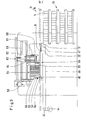
- Fig. 1 there is a first cutting station 1 in the form of a face-cutting machine with an indicated cutting line 2.
- Block strips 4 are separated from the stack 3 from large-area sheet material, the stack 3 being aligned in the usual way on a side stop 5 and by a feed device 6 be advanced step by step.
- the block strips 4 are collected according to FIGS. 1 and 2 at a loading and pre-alignment station 7 on a transport plate 8. At their edges there are two stops 9 and 10 which run perpendicular to one another and by means of which the block strips 4 can be placed next to one another on the transport plate 8 in a perfectly aligned manner.
- the loaded transport plate 8 can be moved from the loading and pre-alignment station to the right into the! 1 and 2 are moved after the stop 9 has moved away in the direction of arrow a and the stop 10 has been moved downward in the direction of arrow b.
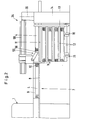
- the loaded transport plate 8 arrives at a transfer station 11, which is formed by a currently effective tier 12 of a buffer shelf 13. This is assigned a lifting device 14 with which the floors 12 can each be brought to the height required for the transfer of the transport plate 8.
- the buffer shelf 13 is mounted on wheels 15 and 16 so that it can be replaced as a whole and can also be loaded and unloaded elsewhere.
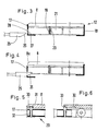
- each tier 12 has two guide rails 17 and 18 running in the loading direction c, between which a transport plate 8 is guided.
- cylindrical rollers 19 are provided, the axes 20 of which extend perpendicular to the loading direction c.
- the rollers are made of plastic, which has a low coefficient of friction.
- the rollers 19 are arranged in three rows and are each mounted in tubular supports 21 with a rectangular cross section.
- the guide rail 17 can be displaced downward by means of a lowering device 22 against the force of a spring, not shown, so that the transport plate 8 can be moved further in the direction of the arrow d.
- the lowering device 22 has two servomotors 23 and 24, here in the form of a pneumatic or hydraulic piston-cylinder unit, each of which has a plunger 25 with an inclined surface 26. When the lowering device 22 is actuated, the inclined surface interacts with the underside 27 of an opening 28 in the guide rail 17 in order to urge the guide rail downward.
- a stop device 29 is provided (FIGS. 5, 6 and 8).
- This stop device consists of a recess 30 on the underside of the transport plate 8 and a catch 31 held on the guide rail 17, which is loaded by a spring 32.
- An inclined surface 33 is connected upstream of the depression, so that the catch 31 is first pressed down before it snaps into the depression 30.
- the catch 31 also emerges from the depression 30, so that the transport plate 8 is thereby released.
- the transfer station 11 connects directly to a second cutting station 34, the cutting line 35 of which is again only indicated by dash-dotted lines.
- This cutting station has a work surface which consists of an input field 36, a work field 37 and an output field 38.
- the input field 36 which roughly comprises the area B1
- the working area 37 which roughly comprises the area B2
- the exit area 38 which can extend over the area B3, serves to receive the finished cut stacks . Where this is desired, these stacks can be processed further in additional processing stations, for example in a bundling station 40 and / or a punching station 41, as is indicated by dash-dotted lines in FIG. 1.
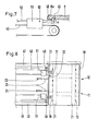
- the cutting station 34 has two guides 42 and 43 of such a length that they extend beyond the actual input field 36.
- the transport plate 8 is moved by a motor.
- a motor 44 drives an endless chain 46 via a drive wheel 45, which chain is guided near the transfer station 11 via a further deflection wheel 47.
- a coupling piece 48 is attached to the chain 46 and can engage in a recess 49 in the transport plate 8.
- the coupling piece 48 is mounted about an axis 50 in the housing of a servomotor 51.
- the servomotor can be operated pneumatically, hydraulically or electrically. If energy is supplied to it via a supply line 52, the coupling piece 48 pivots in the direction of arrow e into the coupling position illustrated in FIG. 7.
- the transport plate 8 can in the direction of arrow d from the transfer station 11 in the area of Input field 36 are drawn.
- a height-adjustable stop 53 which is raised by means of an inclined surface 8a (FIG. 7) from the transport plate 8 moving in the direction d and to which a proximity initiator 54 is assigned.
- the motor 44 is switched off.
- the block strips now have a defined position within the input field 36 of the cutting station 34.
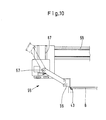
- a feed device 55 has individual segments 56. These can be pivoted upwards from an active position (fully extended in FIG. 10) about an axis 57 arranged behind them into an inactive position (dash-dotted lines in FIG. 10). 1, the effective width of the feed device 55 corresponds to three times the width of a block strip 4. If the feed device 55 is now moved along its path 58 by a desired amount, only the first three block strips are taken along and onto the Work field 37 transferred. By adjusting the effective width of the feed device, it can be adapted to any other number or width of the block strips.
- the pressure slide 39 which presses the block strips against the stop 53 near the cutting line 35, is effective on the working field in order to make a final alignment.
- This pressure slide 39 is actuated by means of a servomotor 60 in the direction of arrow d and can be displaced in height by means of a servomotor 61.
- the carriage i 62 carrying the arrangement can be moved horizontally along a guide 63.
- a hold-down device 64 is also provided, which is also held by the carriage 62 and can be pressed down by means of servomotors 65. He holds the next block strip so that the first three block strips. can be moved without affecting the subsequent block strips.
- Another pressure slide 66 which can be moved in the direction of arrow f, acts on the end faces of the block strips so that they are aligned with the active segments 56 of the feed device 55.
- the transverse alignment with the pressure slide 39 and the longitudinal alignment with the pressure slide 66 require only a minimal outlay, since the advanced block strips already have a defined position. Then a very precise cut is made.
- the block strips are then advanced step by step by means of the feed device 55 and cut in the transverse direction after each new alignment. As soon as the block strips treated in this way have been cut, the feed device 55 returns to its starting position.
- the motor 44 moves the transport plate 8 further in the direction of the arrow d until the now most forward block strip 4 is detected by the proximity switch 54 and the motor is switched off again.
- the step-by-step advancement and the alignment preceding each cut are then repeated by means of the pressure slides 39 and 66.
- a modified loading and pre-alignment station 107 is illustrated in FIG. 11.
- Transport plate 8 and block strips 4 are unchanged.
- the auxiliary stop 110 cannot be lowered downwards, but can be lifted horizontally from the block strip 4 in the direction of the arrow g and then moved upwards along the arrow h by an actuator so that it takes up the position shown in broken lines.
- the loaded transport plate 8 can then be moved under the auxiliary stop 110.
- an air streaking device 64 which has a hold-down device 65 which is formed by a bar 65 of the auxiliary stop 110 which overlaps the transport plate 8.
- This hold-down device can be moved downward by the path i after the moving-off movement g in order to press the block strips 4 onto one edge on the transport plate 8.
- a servomotor 66 in the form of a pneumatic cylinder is provided to generate the contact pressure and to carry out the movements h and i.
- an air spreading element 67 in the form of a rotatable spreading roller which is held on a guide 69 with the interposition of a servomotor 68 in the form of a pneumatic cylinder, so that it is lowered onto the block strips 4 along the path k and then along the transport plate 8 the surface of the block stack 4 can be moved on the way 1, whereby the air is pressed out between the sheets of the block stack. This almost completely prevents the sheets from moving against each other.
- the spreading roller 67 is then returned to the starting position via the paths m and n.
- the vertical movements are made using the Actuator 68, which causes horizontal movements with the aid of an only indicated motor 70 and an associated chain drive.
- the second cutting station and the feed arrangement can be operated largely automatically. There is also the possibility of automatically forwarding the stack of labels located on the exit field 38 to the bundling station 40 or punching station 41. As a result, a single operator is sufficient for the production of the labels, who produces the block strips at the cutting station 1, places them correctly on the loading and pre-aligning station 7 and otherwise only monitors the automatic process of the system.
- the empty transport plates on the side of the input field 36 facing away from the buffer shelf 13 can be removed.
- the servomotors required for the automatic sequence can be operated pneumatically, hydraulically, mechanically, electrically or in any other known manner.
- the loading station can be spatially separated from the pre-alignment station. Conversely, it is also possible to combine the loading station, the pre-alignment station and the transfer station with one another.
- the transport plate 8 can also have air holes in a known manner, in particular only when loaded by a stack of opening air holes, which, when the transport plate 8 is loaded in the station 7 and possibly also when this plate is unloaded, by the active parts of the feed device 55 with a compressed air source get connected.
Landscapes
- Life Sciences & Earth Sciences (AREA)
- Forests & Forestry (AREA)
- Engineering & Computer Science (AREA)
- Mechanical Engineering (AREA)
- Pile Receivers (AREA)
- Feeding Of Workpieces (AREA)
- Feeding Of Articles By Means Other Than Belts Or Rollers (AREA)
- Branching, Merging, And Special Transfer Between Conveyors (AREA)
Abstract
Description
Die Erfindung bezieht sich auf eine Anordnung zum Zuführen von gestapeltem, blattförmigen Gut zu einer Weiterverarbeitungsstation, insbesondere Schneidstation, mit einer Tischfläche, die ein Eingangsfeld zur Aufnahme des Guts und ein Arbeitsfeld für die Weiterverarbeitung aufweist.The invention relates to an arrangement for feeding stacked, sheet-like goods to a further processing station, in particular a cutting station, with a table surface which has an input field for receiving the goods and a working field for further processing.
Eine Zuführanordnung dieser Art ist aus der Hauszeit- schrift "Polar-Information" 18, 1985, Beispiel 1, der Firma A. Mohr Maschinenfabrik bekannt. Stapel aus großflächigem Blattmaterial, beispielsweise Papier, Pappe, Kunststoff-Folie u. dgl., werden von einem höhenverstellbaren Tisch mittels eines Querschiebers von der Seite her auf das Eingangsfeld einer Scheidvorrichtung geschoben, das sich hinter dem Schneidmesser und dem Pressbalken befindet und durch eine ortsfeste Tischfläche gebildet ist. Um die Bewegbarkeit der Stapel zu verbessern, ist sowohl der höhenverstellbare Tisch als auch das Eingangsfeld mit Luftaustrittsöffnungen versehen. Diese weisen Luftventile auf, die bei Belastung durch den Stapel öffnen. Wenn man statt eines Stapels aus großflächigem Blattmaterial gleichzeitig mehrere Stapel aus kleineren Blättern zuführen will, besteht die Gefahr, daß sich diese Stapel beim Querverschieben gegeneinander verlagern. Es bedarf dann einer besonderen Sorgfalt beim Ausrichten der Stapel in der Schneidvorrichtung. Besonders gravierend ist das Problem, wenn die gestapelten Blattgrößen so klein sind, daß sie auf ihrer Bewegungsbahn zeitweilig gar nicht oder nur am Rand von einem aus einer Luftöffnung austretenden Luftstrom beaufschlagt werden.A feed arrangement of this type is known from the in-house magazine "Polar Information" 18, 1985, Example 1, from the A. Mohr Maschinenfabrik company. Stack of large sheet material, such as paper, cardboard, plastic film and. Like., are pushed from a height-adjustable table by means of a cross slide from the side onto the input field of a cutting device, which is located behind the cutting knife and the press beam and is formed by a stationary table surface. In order to improve the mobility of the stacks, both the height-adjustable table and provide the entrance field with air outlet openings. These have air valves that open when loaded by the stack. If you want to feed several stacks of smaller sheets at the same time instead of a stack of large sheet material, there is a risk that these stacks will shift against each other when they are moved laterally. Special care is then required when aligning the stacks in the cutting device. The problem is particularly serious if the stacked sheet sizes are so small that they are temporarily not impacted at all on their path of movement or only at the edge by an air stream emerging from an air opening.
Es ist ferner bekannt, mehrere Stapel aus großflächigem Blattmaterial unter Zwischenlage von Luftbrettern aufeinander zu stapeln. Diese Luftbretter können jeweils in die Höhe der Arbeitsfläche einer Schneidvorrichtung gebracht werden. Sie besitzen an der Oberfläche Luftaustrittsöffnungen, so daß das Verschieben des gesamten Stapels auf das Eingangsfeld der Schneidvorrichtung mit wenig Mühe vor sich gehen kann (Prospekt "Polar-Luftbrettanlage" ND 531203023d der Firma A. Mohr Maschinenfabrik). Solche Luftbretter dienen auch zum Transport einzelner Stapel nach dem Rütteln.It is also known to stack a plurality of stacks of large-area sheet material on top of one another with the interposition of air boards. These air boards can each be brought to the height of the working surface of a cutting device. They have air outlet openings on the surface, so that moving the entire stack onto the input field of the cutting device can be done with little effort (brochure "Polar air board system" ND 531203023d from A. Mohr Maschinenfabrik). Such air boards are also used to transport individual stacks after shaking.
Bei Schneid-, Stanz-, Bündel- und anderen Weiterverarbeitungsstationen ist es wichtig, daß die Stapel des blattförmigen Guts auf dem Arbeitsfeld eine genaue Lage und Ausrichtung haben. Das Ausrichten ist umso schwieriger und zeitaufwendiger, je mehr die Stapel des zugeführten Guts auf dem Eingangsfeld eine Fehlausrichtung aufweisen.In the case of cutting, punching, bundling and other further processing stations, it is important that the stacks of the sheet-like material have an exact position and orientation on the working field. Alignment is all the more difficult and time-consuming, the more the stacks of the fed goods have misalignment on the input field.
Der Erfindung liegt daher die Aufgabe zugrunde, eine Zuführanordnung der eingangs beschriebenen Art anzugeben, bei der das Ausrichten auch dann ein Minimum an Aufwand erfordert, wenn Stapel aus kleineren Blattgrößen und insbesondere gleichzeitig mehrere solcher Stapel kleinerer Blattgrößen zugeführt werden.The invention is therefore based on the object of specifying a feed arrangement of the type described at the outset in which the alignment then also takes a minimum Effort is required if stacks of smaller sheet sizes and in particular several such stacks of smaller sheet sizes are fed simultaneously.
Diese Aufgabe wird erfindungsgemäß dadurch gelöst, daß das Eingangsfeld durch eine Transportplatte gebildet ist, die auf Führungen von einer Übergabestation in die Weiterverarbeitungssstation bewegbar ist.This object is achieved in that the input field is formed by a transport plate which is movable on guides from a transfer station to the further processing station.
Bei dieser Konstruktion ruhen die Stapel bei der gesamten Zuführbewegung bis zum Eingangsfeld auf der Transportplatte. Auch bei kleineren Blattgrößen bleibt die Lage der Stapel auf der Transportplatte und relativ zueinander unverändert. Da sich demnach die Stapel während der Zuführbewegung nicht gegeneinander verschieben, können entsprechende Korrektur-Ausrichtarbeitsgänge entfallen. Die Transportplatte bewegt sich innerhalb der Weiterverarbeitungsstation auf Führungen. Ist ein Stapel auf einer bestimmten Stelle der Transportplatte plaziert, durchläuft er eine definierte Bahn. Auch dies erleichtert den Ausrichtvorgang. Wenn die Transportplatte ihre Funktion als Eingangsfeld einnimmt, ist der Weg von ihr zum Arbeitsfeld kurz. Die üblicherweise für das Verschieben der Stapel vom Eingangsfeld auf das Arbeitsfeld verwendeten Vorschubeinrichtungen reichen aus, um die Stapel wohlgeordnet auf das Arbeitsfeld zu bringen, so daß - wenn überhaupt - nur noch eine minimale Ausrichtung, die sich sehr schnell durchführen läßt, notwendig ist.With this construction, the stacks rest on the transport plate during the entire feed movement up to the entry field. Even with smaller sheet sizes, the position of the stacks on the transport plate and relative to one another remains unchanged. Accordingly, since the stacks do not move against one another during the feed movement, corresponding correction-alignment work steps can be omitted. The transport plate moves on guides within the processing station. If a stack is placed on a specific point on the transport plate, it passes through a defined path. This also facilitates the alignment process. When the transport plate takes on its function as an entry field, the path from it to the work field is short. The feed devices usually used for moving the stacks from the input field to the working field are sufficient to bring the stacks to the working field in a well-ordered manner, so that - if at all - only a minimal alignment, which can be carried out very quickly, is necessary.
Besondere Vorteile bietet es, daß die Führungen etwa senkrecht zu einem Anschlag für das Ausrichten des Guts vor der Weiterverarbeitung verlaufen. Mit Hilfe der Transportplatte können die Stapel so dicht an den Anschlag herangeführt werden, daß ein anschließendes Ausrichten an diesem Anschlag von Hand sehr rasch vor sich geht. Es ist sogar möglich, den Stapel mit Hilfe der Transportplatte bis gegen den Anschlag zu fahren und so eine zumindest teilweise automatische Ausrichtung zu erzielen.It offers particular advantages that the guides run approximately perpendicular to a stop for aligning the material before further processing. With the help of the transport plate, the stacks can be brought so close to the stop that a subsequent alignment on this stop by hand is very quick goes. It is even possible to drive the stack against the stop using the transport plate and thus achieve an at least partially automatic alignment.
Günstig ist es, daß die Transportplatte mittels eines Antriebsmotors längs der Führungen bewegbar ist. Auf diese Weise kann man eine automatische Zuführung erreichen. Bei entsprechender Regelung des Antriebsmotors kann jeder Stapel an einer genau definierten Stelle des Eingangsfeldes zur Ruhe gesetzt werden.It is favorable that the transport plate can be moved along the guides by means of a drive motor. In this way, automatic feeding can be achieved. With appropriate control of the drive motor, each stack can be put to rest at a precisely defined point in the input field.
Inbesondere kann dem Anschlag ein Näherungsinitiator zum Abschalten des Antriebsmotors zugeordnet sein. Die Transportplatte wird daher vom Motor automatisch so weit vorgerückt, bis der in Zuführrichtung vorderste Stapel den Näherungsschalter betätigt.In particular, a proximity initiator for switching off the drive motor can be assigned to the stop. The transport plate is therefore automatically advanced by the motor until the foremost stack in the feed direction actuates the proximity switch.
Mit Vorteil bewegt der Antriebsmotor ein Kupplungsstück längs der Führungen, und die Transportplatte weist Mittel zum Angreifen des Kupplungsstücks auf. Dies ergibt einen wesentlich einfacheren Aufbau, als wenn jede Transportplatte mit einem eigenen Motor versehen würde.The drive motor advantageously moves a coupling piece along the guides, and the transport plate has means for engaging the coupling piece. This results in a much simpler construction than if each transport plate were provided with its own motor.
In weiterer Ausgestaltung der Erfindung ist dafür gesorgt, daß eine Vorschubeinrichtung vorgesehen ist, die das Gut etwa rechtwinklig zu den Führungen von der Transportplatte auf das Arbeitsfeld schiebt, und daß die wirksame Breite der Vorschubeinrichtung geringer als die Länge der Transportplatte ist. Es ist daher möglich, daß die Vorschubeinrichtung nur einen Teil des auf der Transportplatte zugeführten gestapelten Guts mit sich nimmt. Hierdurch läßt sich eine noch ge- nauere Ausrichtung erzielen. Außerdem übernimmt sie die zusätzliche Aufgabe, jeweils den oder die nächsten Stapel in den Wirkungsbereich der Vorschubeinrichtung zu bringen. Auf diese Weise können Stapel mit verhältnismäßig kleiner Blattgröße rationell einer Weiterverarbeitungsstelle zugeführt werden.In a further embodiment of the invention, it is ensured that a feed device is provided which pushes the material from the transport plate onto the work area approximately at right angles to the guides, and that the effective width of the feed device is less than the length of the transport plate. It is therefore possible for the feed device to take with it only a part of the stacked goods supplied on the transport plate. This enables an even more precise alignment to be achieved. In addition, it takes on the additional task of bringing the next stack or stacks into the effective range of the feed device. In this way, stacks with ratio moderately small sheet size can be efficiently fed to a further processing point.
Günstig ist eine außerhalb der Weiterverarbeitungsstatiervorgesehene Beladestation für die Transportplatte. Der Beladevorgang kann weitgehend unabhängig vom Weiterverarbeitungsvorgang vorgenommen werden.A loading station for the transport plate provided outside the further processing station is favorable. The loading process can largely be carried out independently of the further processing process.
Besondere Vorteile bietet eine außerhalb der Weiterverarbeitungsstation befindliche Vorausrichtstation mit wenigstens einem am Rand der Transportplatte verlaufenden Hilfsanschlag. Wenn die Stapel bereits in der Vorausrichtstation eine definierte Lage auf der Transportplatte erhalten haben, besitzen sie diese Lage auch auf dem Eingangsfeld und können daher noch rascher endgültig ausgerichtet werden.A pre-alignment station located outside the further processing station with at least one auxiliary stop running at the edge of the transport plate offers particular advantages. If the stacks have already received a defined position on the transport plate in the pre-alignment station, they also have this position on the entry field and can therefore be finally aligned even more quickly.
Im einfachsten Fall kommt man mit einem Hilfsanschlag aus. Günstig ist es jedoch, zwei rechtwinklig zueinander verlaufende Hilfsanschläge zu verwenden. Auf diese Weise können die Stapel in der Vorausrichtstation zweidimensional genau auf der Transportplatte plaziert werden.In the simplest case, you can get by with an auxiliary stop. However, it is expedient to use two auxiliary stops running at right angles to one another. In this way, the stacks in the pre-alignment station can be placed exactly on the transport plate in two dimensions.
Hierbei ist es empfehlenswert, daß der eine Hilfsanschlag so weit in der Höhe verstellbar ist, daß die beladene Transportplatte über oder unter dem Hilfsanschlag hinweg bewegbar ist. Dies ergibt verhältnismäßig kurze Wege für den Transportplatte.It is recommended that the height of one auxiliary stop is adjustable so that the loaded transport plate can be moved above or below the auxiliary stop. This results in relatively short distances for the transport plate.
Günstig ist es ferner, daß die Beladestation mit einer Luftausstreichvorrichtung versehen ist, die einen Nieder- ! halter und ein hierzu paralleles Ausstreichelement aufweist, das unter Druckbelastung auf der Oberfläche des Stapelguts längs der Transportplatte bewegbar ist. Durch das Herauspressen der Luft zwischen den einzelnen Blättern läßt sich ein Verschieben der einzelnen Blätter gegeneinander weitgehend vermeiden. Es können daher mehrere Stapel nebeneinander, beispielsweise als sogenannte Blockstreifen, angeordnet werden, ohne daß die Gefahr besteht, daß sich die Stapel gegenseitig verzahnen.It is also expedient that the loading station is provided with an air spreading device which has a low! holder and a spreading element parallel thereto, which is movable under pressure on the surface of the stacked goods along the transport plate. By squeezing out the air between the individual sheets, a displacement of the individual sheets against each other can be largely avoided. It can therefore several stacks are arranged side by side, for example as so-called block strips, without the risk that the stacks interlock.
Konstruktiv empfiehlt es sich, daß ein Hilfsanschlag eine die Transportplatte übergreifende Leiste aufweist, die den Niederhalter bildet. Durch die Doppelfunktion des Hilfsanschlags ergibt sich ein geringer Platzbedarf.In terms of construction, it is recommended that an auxiliary stop have a bar that overlaps the transport plate and that forms the hold-down device. The double function of the auxiliary stop results in a small space requirement.
Bei einem bevorzugten Ausführungsbeispiel gibt es ein außerhalb der Weiterverarbeitungsstation befindliches Pufferregal, das mehrere beladene Transportplatten übereinander aufnimmt und so höhenverstellbar ist, daß jede dieser Transportplatten in die Tischebene bringbar ist. Das Pufferregal bietet in Verbindung mit der automatischen Zuführung der Transportplatten die Möglichkeit einer sehr schnellen Beschickung bei der Weiterverarbeitungsstation. Es kann auch eine jeweils leere Transportplatte wieder aufnehmen, sofern diese nicht nach der gegenüberliegenden Seite hin abgeführt wird.In a preferred embodiment there is a buffer shelf located outside the further processing station, which receives several loaded transport plates one above the other and is height-adjustable so that each of these transport plates can be brought to the table level. In connection with the automatic feeding of the transport plates, the buffer rack offers the possibility of very fast loading at the further processing station. It can also pick up an empty transport plate, provided that it is not removed to the opposite side.
Das Pufferregal kann auch als Ganzes auswechselbar sein und daher an anderer Stelle be- und entladen werden.The buffer rack can also be exchangeable as a whole and can therefore be loaded and unloaded elsewhere.
Eine besonders platzsparende Ausgestaltung ergibt sich, wenn die Übergabestation quer zur Weitergaberichtung mit der Transportplatte beschickbar ist, wobei zwei Führungsschienen die Transportplatte zwischen sich führen, und wenn die der Weiterverarbeitungsstation zugewandte Führungsschiene unter die Bewegungsbahn der Transportplatte absenkbar ist.A particularly space-saving design results if the transfer station can be loaded with the transport plate transversely to the direction of transfer, two guide rails guiding the transport plate between them, and if the guide rail facing the processing station can be lowered below the path of movement of the transport plate.
Desweiteren kann die Übergabestation eine Vorrichtung zum Stoppen der Transportplatte bei der Beschickungsbewegung aufweisen. Hierdurch ergibt sich eine Ausrichtung mit Bezug auf die Führungen und eine definierte Lage, in der die Transportplatte vom Kupplungsstück des Motors ergriffen werden kann.Furthermore, the transfer station can have a device for stopping the transport plate during the loading movement. This results in an alignment with respect to the guides and a defined one Position in which the transport plate can be gripped by the coupling piece of the motor.
Insbesondere weist zur Bildung der Stoppvorrichtung die Transportplatte an der Unterseite eine Vertiefung auf, in die eine Raste an der Übergabestation am Ende der Beschickungsbewegung eingreift. Dies ergibt eine besonders einfache Konstruktion.In particular, to form the stop device, the transport plate has a depression on the underside, into which a catch engages at the transfer station at the end of the loading movement. This results in a particularly simple construction.
Günstig ist eine motorisch betätigte Absenkvorrichtung, die gleichzeitig die eine Führungsschiene und die Raste absenkt. Nach Betätigung der Absenkvorrichtung kann die Transportplatte längs der Führungen zum Eingangsfeld bewegt werden.A motorized lowering device is favorable, which simultaneously lowers the one guide rail and the catch. After actuating the lowering device, the transport plate can be moved along the guides to the entry field.
Empfehlenswert ist es, daß die Transportplatte zumindest über einen Teil ihrer Bewegungsbahn mit ihrer Unterseite auf Rollen abgestützt ist. Zumindest dort, wo die Zuführbewegung von Hand erfolgt, sind derartige Rollen zum leichteren Verschieben der Transportplatte nützlich. Hierbei genügt es, wenn sich die Rollen um senkrecht zur Bewegungsbahn verlaufende Achsen drehen, also einen verhältnismäßig einfachen Aufbau haben.It is recommended that the transport plate is supported on its underside on rollers over at least part of its movement path. At least where the feeding movement is done by hand, such rollers are useful for easier displacement of the transport plate. In this case, it is sufficient if the rollers rotate about axes running perpendicular to the movement path, that is to say they have a relatively simple structure.
Bei einer bevorzugten Ausführungsform ist dafür gesorgt, daß sich die Belade- und Vorausrichtstation im Bereich einer ersten Schneidstation befindet, die für die Erzeugung von Blockstreifen durch Parallelschnitte ausgelegt ist, und daß sich die Übergabestation nahe einer zweiten Schneidstation befindet, die für das Zerschneiden der Blockstreifen in Querrichtung ausgelegt ist. Eine solche Anordnung ermöglicht es, auf sehr rationelle Weise Stapel mit verhältnismäßig kleiner Blattgröße zu erzeugen. Denn die Transportplatte, die nahe der ersten Schneidstation mit Blockstreifen beladen wird, vermag diese 1 Blockstreifen in guter Ausrichtung der zweiten Schneidstation zuzuführen, so daß dort nur noch geringfügige Ausrichtarbeitsgänge erforderlich sind. Wenn die zweite Schneidstation eine Vorschubeinrichtung begrenzter Breite hat, können die Blockstreifen nicht nur zugeführt, sondern auch einzeln oder in geringer Anzahl der Vorschubeinrichtung vorgelegt werden.In a preferred embodiment it is ensured that the loading and pre-aligning station is located in the area of a first cutting station, which is designed for the production of block strips by parallel cuts, and that the transfer station is located near a second cutting station, which is used for cutting the block strips is designed in the transverse direction. Such an arrangement makes it possible to produce stacks with a relatively small sheet size in a very efficient manner. Because the transport plate, which is loaded with block strips near the first cutting station, can feed these 1 block strips in good alignment to the second cutting station, so that there are only minor ones Alignment operations are required. If the second cutting station has a feed device of limited width, the block strips can not only be fed, but can also be presented individually or in small numbers to the feed device.
Die Erfindung wird nachstehend anhand eines in der Zeichnung dargestellten, bevorzugten Ausführungsbeispiels näher erläutert. Es zeigen:
- Fig. 1 eine Draufsicht auf eine erfindungsgemäße Anordnung mit zwei Schneidstationen,
- Fig. 2 eine Vorderansicht in Richtung des Pfeiles A der Fig. 1,
- Fig. 3 einen Schnitt längs der Linie B-B der Fig. 1 durch eine Etage eines Pufferregals,
- Fig. 4 die linke Seite der Fig. 3 mit abgesenkter Führungsschiene,
- Fig. 5 einen Schnitt im Bereich einer Vorrichtung zum Stoppen einer Transportplatte,
- Fig. 6 eine Seitenansicht der Vertiefung der Stoppvorrichtung,
- Fig. 7 einen Schnitt im Bereich der Angriffsstelle eines Kupplungsstücks,
- Fig. 8 eine Draufsicht auf eine Etage des Pufferregals mit anschließenden Teilen einer Schneidstation,
- Fig. 9 eine Ansicht von hinten auf die Schneidstation,
- Fig. 10 eine Seitenansicht der Vorschubeinrichtung und
- Fig. 11 eine Abwandlung der Belade- und Vorausrichtstation.
- 1 is a plan view of an arrangement according to the invention with two cutting stations,
- 2 is a front view in the direction of arrow A of FIG. 1,
- 3 shows a section along the line BB of FIG. 1 through a floor of a buffer shelf,
- 4 shows the left side of FIG. 3 with the guide rail lowered,
- 5 shows a section in the area of a device for stopping a transport plate,
- 6 is a side view of the recess of the stop device,
- 7 shows a section in the area of the point of engagement of a coupling piece,
- 8 is a plan view of a floor of the buffer rack with adjoining parts of a cutting station,
- 9 is a rear view of the cutting station,
- Fig. 10 is a side view of the feed device and
- 11 shows a modification of the loading and pre-aligning station.
In Fig. 1 gibt es eine erste Schneidstation 1 in der Form einer Planschneidmaschine mit einer angedeuteten Schnittlinie 2. Mit ihr werden von Stapel 3 aus großflächigem Blattmaterial Blockstreifen 4 abgetrennt, wobei die Stapel 3 in üblicher Weise an einem Seitenanschlag 5 ausgerichtet und durch eine Vorschubeinrichtung 6 schrittweise vorgeschoben werden.In Fig. 1 there is a first cutting station 1 in the form of a face-cutting machine with an
Die Blockstreifen 4 werden gemäß den Fig. 1 und 2 an einer Belade- und Vorausrichtstation 7 auf einer Transportplatte 8 gesammelt. An deren Rändern gibt es zwei i senkrecht zueinander verlaufende Anschläge 9 und 10, mit deren Hilfe die Blockstreifen 4 einwandfrei ausgerichtet nebeneinander auf der Transportplatte 8 plaziert werden können. Die beladene Transportplatte 8 kann aus der Belade- und Vorausrichtstation nach rechts in den ! Fig. 1 und 2 verschoben werden, nachdem der Anschlag 9 in Richtung des Pfeils a weggerückt und der Anschlag 10 in Richtung des Pfeils b nach unten verlagert worden ist.The block strips 4 are collected according to FIGS. 1 and 2 at a loading and
Die beladene Transportplatte 8 gelangt zu einer Übergabestation 11, die durch eine gerade wirksame Etage 12 eines Pufferregals 13 gebildet ist. Diesem ist eine Hubvorrichtung 14 zugeordnet, mit der die Etagen 12 jeweils in die für die Übergabe der Transportplatte 8 erforderliche Höhe gebracht werden können. Das Pufferregal 13 ist auf Rädern 15 und 16 gelagert, so daß es als Ganzes ausgewechselt werden und auch an anderer Stelle be- und entladen werden kann.The loaded
Wie sich aus den Fig. 3 und 8 ergibt, weist jede Etage 12 zwei in Beschickungsrichtung c verlaufende Führungs- schienen 17 und 18 auf, zwischen denen eine Transportplatte 8 geführt wird. Zur Abstützung der Transportplatte sind zylindrische Rollen 19 vorgesehen, deren Achsen 20 sich senkrecht zur Beschickungsrichtung c erstrecken. Die Rollen bestehen aus Kunststoff, der einen geringen Reibungskoeffizienten aufweist. Die Rollen 19 sind in drei Reihen angeordnet und jeweils in rohrförmigen Trägern 21 mit rechteckigem Querschnitt gelagert.3 and 8, each
Die Führungsschiene 17 ist mittels einer Absenkvorrich- tung 22 gegen die Kraft einer nicht veranschaulichten Feder nach unten verlagerbar, damit die Transportplatte 8 in Richtung des Pfeiles d weiterbewegt werden kann. Die Absenkvorrichtung 22 weist zwei Stellmotoren 23 und 24, hier in der Form einer pneumatischen oder hydraulischen Kolben-Zylinder-Einheit, auf, die jeweils einen Stössel 25 mit einer Schrägfläche 26 besitzen. Bei Betätigung der Absenkvorrichtung 22 wirkt die Schrägfläche mit der Unterseite 27 eines Durchbruchs 28 in der Führungsschiene 17 zusammen, um die Führungsschiene nach unten zu drängen.The
Damit die Transportplatte 8 in einer definierten Lage auf der Etage 12 zur Ruhe kommt, ist eine Stoppvorrichtung 29 vorgesehen (Fig. 5, 6 und 8). Diese Stoppvorrichtung besteht aus einer Vertiefung 30 an der Unterseite der Transportplatte 8 und einer an der Führungsschiene 17 gehaltenen Raste 31, die durch eine Feder 32 belastet ist. Der Vertiefung ist eine Schrägfläche 33 vorgeschaltet, so daß die Raste 31 zunächst niederge- drückt wird, bevor sie in die Vertiefung 30 einschnappt. Beim Absenken der Führungsschiene 17 tritt auch die Raste 31 aus der Vertiefung 30 aus, so daß die Transportplatte 8 hierdurch freigegeben wird.So that the
Die Übergabestation 11 schließt unmittelbar an eine zweite Schneidstation 34 an, deren Schnittlinie 35 wiederum nur strichpunktiert angedeutet ist. Diese Schneidstation besitzt eine Arbeitsfläche, die aus einem Eingangsfeld 36, einem Arbeitsfeld 37 und einem Ausgangsfeld 38 besteht. Das Eingangsfeld 36, das etwa den Bereich B1 umfaßt, wird durch jeweils eine Transportplatte 8 gebildet. Das Arbeitsfeld 37, das etwa den Bereich B2 umfaßt, befindet sich unterhalb des Schneidmessers und des Preßbalkens, die nicht veranschaulicht sind, sowie eines Andruckschiebers 39. Das Ausgangsfeld 38, das sich über den Bereich B3 erstrecken kann, dient zur Aufnahme der fertig geschnittenen Stapel. Wo dies erwünscht ist, können diese Stapel in zusätzlichen Verarbeitungsstationen weiterbehandelt werden, beispielsweise in einer Bündelstation 40 und/oder einer Stanzstation 41, wie dies strichpunktiert in Fig. 1 angedeutet ist.The
Im Anschluß an die Übergabestation 11 besitzt die Schneidstation 34 zwei Führungen 42 und 43 von einer solchen Länge, daß sie sich über das eigentliche Eingangsfeld 36 hinaus erstrecken. Längs dieser Führungen wird die Transportplatte 8 motorisch bewegt. Zu diesem Zweck treibt ein Motor 44 über ein Antriebsrad 45 eine endlose Kette 46, die nahe der Übergabestation 11 über ein weiteres Umlenkrad 47 geführt ist. An der Kette 46 ist ein Kupplungsstück 48 befestigt, das in eine Vertiefung 49 der Transportplatte 8 einzugreifen vermag. Das Kupplungsstück 48 ist um eine Achse 50 in dem Gehäuse eines Stellmotors 51 gelagert. Der Stellmotor kann pneumatisch, hydraulisch oder elektrisch betätigt werden. Wenn ihm über eine Zuleitung 52 Energie zugeführt wird, schwenkt das Kupplungsstück 48 in Richtung des Pfeiles e in die in Fig. 7 veranschaulichte Kupplungsstellung. Alsdann kann die Transportplatte 8 in Richtung des Pfeiles d von der Übergabestation 11 in den Bereich des Eingangsfeldes 36 gezogen werden. Am Ende des Eingangs- ; feldes befindet sich ein höhenverstellbarer Anschlag 53, der mittels einer Schrägfläche 8a (Fig. 7) von der sich in Richtung d bewegten Transportplatte 8 angehoben wird und dem ein Näherungsinitiator 54 zugeordnet ist. Sobald der Näherungsinitiator die Annäherung des ersten Blockstreifens 4 auf der Transportplatte 8 signalisiert, wird der Motor 44 abgeschaltet. Die Blockstreifen haben nunmehr eine definierte Lage innerhalb des Eingangsfeldes 36 der Schneidstation 34.Following the
Eine Vorschubeinrichtung 55 weist einzelne Segmente 56 auf. Diese können aus einer wirksamen Stellung (voll ausgezogen in Fig. 10) um eine dahinter angeordnete Achse 57 nach oben in eine unwirksame Stellung (strichpunktiert in Fig. 10) geschwenkt werden. In der Darstellung des Ausführungsbeispiels der Fig. 1 entspricht die wirksame Breite der Vorschubeinrichtung 55 der drei- fachen Breite eines Blockstreifens 4. Wird nun die Vorschubeinrichtung 55 längs ihrer Bahn 58 um ein gewolltes Maß bewegt, werden lediglich die ersten drei Blockstreifen mitgenommen und auf das Arbeitsfeld 37 überführt. Durch Verstellung der wirksamen Breite der Vorschubein- richtung kann eine Anpassung an eine beliebige andere Anzahl oder Breite der Blockstreifen vorgenommen werden.A
Auf dem Arbeitsfeld ist der Andruckschieber 39 wirksam, der nahe der Schnittlinie 35 die Blockstreifen gegen den Anschlag 53 preßt, um eine endgültige Ausrichtung vorzunehmen. Dieser Andruckschieber 39 wird mittels eines Stellmotors 60 in Richtung des Pfeils d betätigt und kann mit Hilfe eines Stelllmotors 61 in der Höhe verlagert werden. Der die Anordnung tragende Schlitten i 62 kann längs einer Führung 63 horizontal verschoben werden.The
Ferner ist ein Niederhalter 64 vorgesehen, der ebenfalls vom Schlitten 62 gehalten und mit Hilfe von Stellmotoren 65 nach unten gedrückt werden kann. Er hält den nächsten Blockstreifen fest, so daß die drei ersten Blockstreifer. verschoben werden können, ohne daß die anschließenden Blockstreifen hierdurch beeinflußt werden können.A hold-down
Ein weiterer Andruckschieber 66, der in Richtung des Pfeiles f verschoben werden kann, wirkt auf die Stirnseiten der Blockstreifen, damit diese an den wirksamen Segmenten 56 der Vorschubvorrichtung 55 ausgerichtet werden. Die Querausrichtung mit dem Andruckschieber 39 und die Längsausrichtung mit dem Andruckschieber 66 erfordert nur einen minimalen Aufwand, da die vorgeschobenen Blockstreifen bereits eine definierte Lage haben. Anschließend erfolgt ein sehr genauer Schnitt.Another
Danach werden die Blockstreifen mittels der Vorschubvorrichtung 55 schrittweise weiter vorgeschoben und jeweils nach erneuter Ausrichtung - in Querrichtung geschnitten. Sobald die so behandelten Blockstreifen fertig geschnitten worden sind, kehrt die Vorschubeinrichtung 55 in ihre Ausgangslage zurück. Der Motor 44 bewegt die Transportplatte 8 in Richtung des Pfeiles d weiter, bis der nunmehr vorderste Blockstreifen 4 vom Näherungsinitiator 54 erfaßt und der Motor wieder abgeschaltet wird. Darauf wiederholt sich das schrittweise Vorschieben und das jeweils einem Schnitt vorausgehende Ausrichten mittels der Andruckschieber 39 und 66.The block strips are then advanced step by step by means of the
Man kann auch die Transportplatte 8 schon in Richtung des Pfeiles d weiterbewegen, während die Vorschubvorrichtung 55 zurückbewegt wird, wenn diese mit Hilfe der Vertikalführung 67 über die Blockstreifen 4 angehoben wird. Ist die Transportplatte 8 leer, wird sie durch Richtungsumkehr des Motors 44 in eine freie Etage des Regals 13 zurückgeführt. Dann wird eine beladene Transportplatte 8 in die Höhe der Übergabestation gebracht, worauf sich das Arbeitsspiel wiederholt.You can also move the
In Fig. 11 ist eine abgewandelte Belade- und Vorausrichtstation 107 veranschaulicht. Transportplatte 8 und Blockstreifen 4 sind unverändert. Der Hilfsanschlag 110 ist jedoch nicht nach unten absenkbar, sondern er kann in Richtung des Pfeiles g horizontal vom Blockstreifen 4 abgehoben und dann längs des Pfeiles h so weit durch einen Stellmotor nach oben bewegt werden, daß er die gestrichelte Lage einnimmt. Alsdann kann die beladene Transportplatte 8 unter dem Hilfsanschlag 110 hindurchbewegt werden.A modified loading and
Außerdem ist eine Luftausstreichvorrichtung 64 vorgesehen, die einen Niederhalter 65, der durch eine die Transportplatte 8 übergreifende Leiste 65 des Hilfsanschlages 110 gebildet wird. Dieser Niederhalter kann nach der Abrückbewegung g um den Weg i nach unten bewegt werden, um die Blockstreifen 4 an ihrer einen Kante auf der Transportplatte 8 festzupressen. Zur Erzeugung des Anpreßdrucks und zur Durchführung der Bewegungen h und i ist ein Stellmotor 66 in der Form eines pneumatischen Zylinders vorgesehen. Ferner ist ein Luftausstreichelement 67 in Form einer drehbaren Ausstreichwalze vorhanden, die unter Zwischenschaltung eines Stellmotors 68 in der Form eines pneumatischen Zylinders an einer Führung 69 gehalten ist, so daß sie auf die Blockstreifen 4 längs des Weges k abgesenkt und dann längs der Transportplatte 8 auf der Oberfläche der Blockstapel 4 auf dem Weg 1 bewegt werden kann, wodurch die Luft zwischen den Blättern der Blockstapel herausgepreßt wird. Dadurch wird ein Verschieben der Blätter gegeneinander fast vollständig vermieden. Die Ausstreichwalze 67 wird dann über die Wege m und n in die Ausgangsstellung zurückgeführt. Die vertikalen Bewegungen werden mit Hilfe des Stellmotors 68, die horizontalen Bewegungen mit Hilfe eines nur angedeuteten Motors 70 und eines zugehörigen Kettentriebs bewirkt.In addition, an
Die zweite Schneidstation und die Zuführanordnung können weitgehend automatisch betrieben werden. Es besteht auch die Möglichkeit, die auf dem Ausgangsfeld 38 befindlichen Etikettenstapel automatisch an die Bündelstation 40 oder Stanzstation 41 weiterzuleiten. Infolgedessen genügt für die Herstellung der Etiketten eine einzige Bedienungsperson, die an der Schneidstation 1 die Blockstreifen herstellt, sie auf der Belade- und Vorausrichtstation 7 richtig plaziert und im übrigen lediglich den automatischen Ablauf der Anlage überwacht.The second cutting station and the feed arrangement can be operated largely automatically. There is also the possibility of automatically forwarding the stack of labels located on the
Von der beschriebenen Ausführungsform kann in vielfacher Hinsicht abgewichen werden, ohne den Grundgedanken der Erfindung zu verlassen. Beispielsweise können die leeren Transportplatten auf der dem Pufferregal 13 abgewandten Seite des Eingangsfeldes 36 abgenommen werden. Die für den automatischen Ablauf erforderlichen Stellmotoren können pneumatisch, hydraulisch, mechanisch, elektrisch oder auf sonstige bekannte Weise betrieben werden. Die Beladestation kann räumlich von der Vorausrichtstation getrennt sein. Umgekehrt ist es auch möglich, die Beladestation, die Vorausrichtstation und die Übergabestation miteinander zu vereinigen. Die Transportplatte 8 kann auch in bekannter Weise Luftlöcher, insbesondere nur bei Belastung durch einen Stapel öffenende Luftlöcher, aufweisen, die beim Beladen der Transportplatte 8 in der Station 7 und ggf. auch beim Entladen dieser Platte durch die wirksamen Teile der Vorschubeinrichtung 55 mit einer Druckluftquelle verbunden werden.There can be deviations from the described embodiment in many respects without departing from the basic idea of the invention. For example, the empty transport plates on the side of the
Claims (21)
Applications Claiming Priority (2)
| Application Number | Priority Date | Filing Date | Title |
|---|---|---|---|
| DE3613315 | 1986-04-19 | ||
| DE19863613315 DE3613315A1 (en) | 1986-04-19 | 1986-04-19 | ARRANGEMENT FOR FEEDING STACKED, SHEET-SHAPED GOODS TO A PROCESSING STATION, IN PARTICULAR CUTTING STATION |
Publications (3)
| Publication Number | Publication Date |
|---|---|
| EP0242762A2 true EP0242762A2 (en) | 1987-10-28 |
| EP0242762A3 EP0242762A3 (en) | 1989-12-06 |
| EP0242762B1 EP0242762B1 (en) | 1991-07-03 |
Family
ID=6299100
Family Applications (1)
| Application Number | Title | Priority Date | Filing Date |
|---|---|---|---|
| EP87105448A Expired - Lifetime EP0242762B1 (en) | 1986-04-19 | 1987-04-13 | Apparatus for feeding a pile of sheets to a cutting apparatus |
Country Status (5)
| Country | Link |
|---|---|
| US (1) | US5150647A (en) |
| EP (1) | EP0242762B1 (en) |
| JP (1) | JPH0825158B2 (en) |
| DE (2) | DE3613315A1 (en) |
| ES (1) | ES2023375B3 (en) |
Cited By (5)
| Publication number | Priority date | Publication date | Assignee | Title |
|---|---|---|---|---|
| EP0453935A1 (en) * | 1990-04-26 | 1991-10-30 | Wolfgang Mohr | Method and device for transporting stacked sheet material from a delivery field to a feeding field in a cutting machine |
| EP0455134A1 (en) * | 1990-05-03 | 1991-11-06 | GIBEN IMPIANTI S.p.A. | Apparatus for transferring stacks of panels in a cutting plant of the angular type |
| EP0641631A1 (en) * | 1993-08-26 | 1995-03-08 | Kolbus GmbH & Co. KG | Method and machine for three-sided cutting of stacked books, brochures or the same |
| EP2179823A1 (en) | 2008-10-10 | 2010-04-28 | Adolf Mohr Maschinenfabrik GmbH & Co. KG | Method of creating pre-trimmed stacks using a guillotine |
| EP2228182A1 (en) | 2009-03-11 | 2010-09-15 | Adolf Mohr Maschinenfabrik GmbH & Co. KG | Method of creating pre-trimmed stacks using a guillotine |
Families Citing this family (10)
| Publication number | Priority date | Publication date | Assignee | Title |
|---|---|---|---|---|
| DE3941273A1 (en) * | 1989-12-14 | 1991-06-20 | Rockwool Mineralwolle | METHOD FOR THE HEAT AND / OR SOUND INSULATION OF BUILDINGS |
| JP2694585B2 (en) * | 1991-12-19 | 1997-12-24 | 富士写真フイルム株式会社 | Cutting device, air venting device and sheet overlap prevention device |
| US5694823A (en) * | 1994-10-18 | 1997-12-09 | The Challenge Machinery Company | Document trimming apparatus |
| DE19523699A1 (en) * | 1995-06-29 | 1997-01-09 | Will E C H Gmbh & Co | Device for removing air pockets from paper stacks |
| EP0936166A1 (en) * | 1998-02-10 | 1999-08-18 | E.I. Du Pont De Nemours And Company | High speed cutting assembly |
| DE59807671D1 (en) * | 1998-12-28 | 2003-04-30 | Mohr Adolf Maschf | Process for the formation and processing of small stacks of sheets |
| DE19926073C2 (en) * | 1999-06-08 | 2001-05-10 | Polar Bandpack Buendelmaschine | Device for handling flat cut products |
| EP1172185A1 (en) * | 2000-07-14 | 2002-01-16 | Adolf Mohr Maschinenfabrik GmbH & Co. KG | Device for cutting sheet material |
| US7097727B2 (en) * | 2003-05-06 | 2006-08-29 | 3M Innovative Properties Company | Inline accumulating die padder |
| JP4780604B2 (en) * | 2005-10-07 | 2011-09-28 | カール事務器株式会社 | Paper positioning mechanism |
Citations (3)
| Publication number | Priority date | Publication date | Assignee | Title |
|---|---|---|---|---|
| DE2449684A1 (en) * | 1973-10-26 | 1975-04-30 | Minolta Camera Kk | PAPER CUTTER FOR COPY MACHINES |
| EP0091714A1 (en) * | 1982-04-08 | 1983-10-19 | De La Rue Giori S.A. | Method and apparatus for making ready printed, numbered and cut to size bank notes |
| EP0135029A1 (en) * | 1983-08-19 | 1985-03-27 | International Business Machines Corporation | Docking and fixing device for a pallet in a robot or like system |
Family Cites Families (22)
| Publication number | Priority date | Publication date | Assignee | Title |
|---|---|---|---|---|
| US1883449A (en) * | 1929-08-10 | 1932-10-18 | Box Blank Corp | Packing process for silk yarn and the like |
| US2376470A (en) * | 1944-02-26 | 1945-05-22 | Int Paper Co | Sheet cutter |
| US2834388A (en) * | 1954-10-04 | 1958-05-13 | Us Slicing Machine Co Inc | Slicing machine slicer, stacker, and weigher |
| DE1144685B (en) * | 1959-11-12 | 1963-03-07 | Southworth Machine Co | Device for conveying paper sheets, z. B. in a paper cutting machine |
| US3165956A (en) * | 1962-05-02 | 1965-01-19 | Miehle Goss Dexter Inc | Paper pile aligner for automatic cutter |
| US3424044A (en) * | 1966-03-10 | 1969-01-28 | Miehle Goss Dexter Inc | Continuous three-knife trimmer |
| DE2225910A1 (en) * | 1972-05-27 | 1973-12-13 | Baumann Heinrich | DEVICE FOR SUPPLYING PARTIAL STACKS OF PAPER SHEETS TO A COMPLETE STACK |
| US4034636A (en) * | 1975-07-16 | 1977-07-12 | Gerber Garment Technology, Inc. | Method and apparatus for placing a multi-ply layup of sheet material on a work table |
| US4036381A (en) * | 1975-09-05 | 1977-07-19 | International Business Machines Corporation | Apparatus for transferring sample holders relative to a movable magazine |
| DE2723162A1 (en) * | 1977-05-23 | 1978-11-30 | Mohr | Paper cutting machine partial stack transfer mechanism - has end and side grabs travelling to and from support |
| DE2758291C3 (en) * | 1977-12-27 | 1980-07-10 | Jagenberg-Werke Ag, 4000 Duesseldorf | Stack changing device |
| US4364311A (en) * | 1980-09-05 | 1982-12-21 | Platt Iii James B | Precision trimming and precision cross-cutting apparatus and method for bulk material |
| CH639045A5 (en) * | 1981-02-03 | 1983-10-31 | Bobst Sa | DEVICE FOR INSERTING SHEET PACKETS INTO A WORKING MACHINE. |
| JPS58102699A (en) * | 1981-12-16 | 1983-06-18 | 株式会社共同精機工作所 | Method of cutting and treating sheet |
| US4509417A (en) * | 1983-02-12 | 1985-04-09 | E.C.H. Will (Gmbh & Co.) | Apparatus for expelling air from stacks of paper sheets or the like |
| US4588341A (en) * | 1983-07-08 | 1986-05-13 | Motoda Denshi Kogyo Kabushiki Kaisha | Article delivery apparatus |
| US4720463A (en) * | 1985-03-01 | 1988-01-19 | Sherwood Medical Company | Automated microbiological testing apparatus |
| DE3540203C2 (en) * | 1985-11-13 | 1993-12-09 | Will E C H Gmbh & Co | Device for conveying stacks of paper |
| US4641555A (en) * | 1986-01-31 | 1987-02-10 | Johnson Dewey A | Paper handling system |
| DE3644872A1 (en) * | 1986-02-05 | 1987-09-03 | Womako Masch Konstr | Guillotine-type cutter for the transverse severing of stacks of paper |
| DE3623004A1 (en) * | 1986-07-09 | 1988-01-28 | Wolfgang Mohr | SURFACE MACHINE |
| US4984516A (en) * | 1988-10-07 | 1991-01-15 | Attilio Scalzitti | Apparatus for removing fluid from overlapping sheets of material |
-
1986
- 1986-04-19 DE DE19863613315 patent/DE3613315A1/en active Granted
-
1987
- 1987-04-13 EP EP87105448A patent/EP0242762B1/en not_active Expired - Lifetime
- 1987-04-13 DE DE8787105448T patent/DE3771114D1/en not_active Expired - Fee Related
- 1987-04-13 ES ES87105448T patent/ES2023375B3/en not_active Expired - Lifetime
- 1987-04-17 JP JP62096100A patent/JPH0825158B2/en not_active Expired - Lifetime
-
1989
- 1989-10-26 US US07/427,979 patent/US5150647A/en not_active Expired - Lifetime
Patent Citations (3)
| Publication number | Priority date | Publication date | Assignee | Title |
|---|---|---|---|---|
| DE2449684A1 (en) * | 1973-10-26 | 1975-04-30 | Minolta Camera Kk | PAPER CUTTER FOR COPY MACHINES |
| EP0091714A1 (en) * | 1982-04-08 | 1983-10-19 | De La Rue Giori S.A. | Method and apparatus for making ready printed, numbered and cut to size bank notes |
| EP0135029A1 (en) * | 1983-08-19 | 1985-03-27 | International Business Machines Corporation | Docking and fixing device for a pallet in a robot or like system |
Cited By (6)
| Publication number | Priority date | Publication date | Assignee | Title |
|---|---|---|---|---|
| EP0453935A1 (en) * | 1990-04-26 | 1991-10-30 | Wolfgang Mohr | Method and device for transporting stacked sheet material from a delivery field to a feeding field in a cutting machine |
| EP0455134A1 (en) * | 1990-05-03 | 1991-11-06 | GIBEN IMPIANTI S.p.A. | Apparatus for transferring stacks of panels in a cutting plant of the angular type |
| EP0641631A1 (en) * | 1993-08-26 | 1995-03-08 | Kolbus GmbH & Co. KG | Method and machine for three-sided cutting of stacked books, brochures or the same |
| EP2179823A1 (en) | 2008-10-10 | 2010-04-28 | Adolf Mohr Maschinenfabrik GmbH & Co. KG | Method of creating pre-trimmed stacks using a guillotine |
| EP2228182A1 (en) | 2009-03-11 | 2010-09-15 | Adolf Mohr Maschinenfabrik GmbH & Co. KG | Method of creating pre-trimmed stacks using a guillotine |
| US8387498B2 (en) | 2009-03-11 | 2013-03-05 | Adolf Mohr Maschinenfabrik Gmbh & Co. Kg | Method for cutting stacks of sheet material |
Also Published As
| Publication number | Publication date |
|---|---|
| DE3613315A1 (en) | 1987-10-22 |
| JPS62249843A (en) | 1987-10-30 |
| DE3613315C2 (en) | 1989-06-22 |
| ES2023375B3 (en) | 1992-01-16 |
| JPH0825158B2 (en) | 1996-03-13 |
| US5150647A (en) | 1992-09-29 |
| DE3771114D1 (en) | 1991-08-08 |
| EP0242762B1 (en) | 1991-07-03 |
| EP0242762A3 (en) | 1989-12-06 |
Similar Documents
| Publication | Publication Date | Title |
|---|---|---|
| EP0242763B1 (en) | Apparatus for cutting piles of sheets | |
| EP0242762B1 (en) | Apparatus for feeding a pile of sheets to a cutting apparatus | |
| DE2931780A1 (en) | DEVICE FOR DIVIDING A PLATE IN SMALL FORMAT CUTTINGS | |
| EP0494404A1 (en) | Plate feed apparatus for plate-dividing saws | |
| EP2243606B1 (en) | Assembly for producing boards from wooden lamellae and method for producing such boards | |
| EP0252418A1 (en) | Guillotine-type cutter | |
| EP0253165B1 (en) | Sheet feeder | |
| DE3716666C2 (en) | Panel slicer with a rip saw and a cross saw | |
| EP1018408B1 (en) | Guillotine-type machine for cutting stacked sheet material | |
| DE3515729C2 (en) | ||
| EP1018409A1 (en) | Method for forming and further processing of small stacks of sheet material | |
| DE8014325U1 (en) | MACHINE FOR SCRAPING PANELS, ESPECIALLY FOR PRINTED CIRCUITS | |
| DE4224010A1 (en) | Handling device for strip or sheet of paper - incorporates cross-beams and longitudinal support for tool-carrying positioner guided across path of incoming material | |
| EP0453806B1 (en) | Installation for staking of separate individual slab-shaped work pieces or packs of such workpieces | |
| DE60102097T2 (en) | Boom station of a molding press and tool set for such a station | |
| EP0751086B1 (en) | Device for removing air inclusions from paper stacks | |
| DE19926822A1 (en) | Device to transfer stacked sheets of paper from one pallet to another in printing house has number of support rods disposed in rake fashion to temporarily catch under stack of paper and which with ends supported are vertically movable | |
| DE1953150B2 (en) | Device for scratching glass panels | |
| EP0489681B1 (en) | Method and apparatus for moving closely juxtaposed stacked strips or panel shaped workpieces on a low friction work support surface | |
| DE3317084C2 (en) | ||
| EP1186559A2 (en) | Stacking device | |
| DE3616921C2 (en) | ||
| DE1410039C (en) | Large area punching machine with several punching table tops | |
| DE3226454C2 (en) | Device for joining and conveying strips cut from panels | |
| DE1461362C (en) | Device for aligning the edges of stacks of paper sheets on an automatically operated paper processing machine, such as a punching or bookbinding machine |
Legal Events
| Date | Code | Title | Description |
|---|---|---|---|
| PUAI | Public reference made under article 153(3) epc to a published international application that has entered the european phase |
Free format text: ORIGINAL CODE: 0009012 |
|
| AK | Designated contracting states |
Kind code of ref document: A2 Designated state(s): BE CH DE ES FR GB IT LI NL SE |
|
| PUAL | Search report despatched |
Free format text: ORIGINAL CODE: 0009013 |
|
| AK | Designated contracting states |
Kind code of ref document: A3 Designated state(s): BE CH DE ES FR GB IT LI NL SE |
|
| 17P | Request for examination filed |
Effective date: 19900120 |
|
| 17Q | First examination report despatched |
Effective date: 19900828 |
|
| GRAA | (expected) grant |
Free format text: ORIGINAL CODE: 0009210 |
|
| AK | Designated contracting states |
Kind code of ref document: B1 Designated state(s): BE CH DE ES FR GB IT LI NL SE |
|
| ITF | It: translation for a ep patent filed |
Owner name: JACOBACCI & PERANI S.P.A. |
|
| REF | Corresponds to: |
Ref document number: 3771114 Country of ref document: DE Date of ref document: 19910808 |
|
| GBT | Gb: translation of ep patent filed (gb section 77(6)(a)/1977) | ||
| ET | Fr: translation filed | ||
| REG | Reference to a national code |
Ref country code: ES Ref legal event code: FG2A Ref document number: 2023375 Country of ref document: ES Kind code of ref document: B3 |
|
| PLBE | No opposition filed within time limit |
Free format text: ORIGINAL CODE: 0009261 |
|
| STAA | Information on the status of an ep patent application or granted ep patent |
Free format text: STATUS: NO OPPOSITION FILED WITHIN TIME LIMIT |
|
| 26N | No opposition filed | ||
| EAL | Se: european patent in force in sweden |
Ref document number: 87105448.2 |
|
| REG | Reference to a national code |
Ref country code: CH Ref legal event code: PUE Owner name: WOLFGANG MOHR TRANSFER- ADOLF MOHR MASCHINENFABRIK |
|
| REG | Reference to a national code |
Ref country code: FR Ref legal event code: TP |
|
| NLS | Nl: assignments of ep-patents |
Owner name: ADOLF MOHR MASCHINENFABRIK GMBH & CO. KG |
|
| REG | Reference to a national code |
Ref country code: GB Ref legal event code: 732E |
|
| REG | Reference to a national code |
Ref country code: ES Ref legal event code: PC2A |
|
| PGFP | Annual fee paid to national office [announced via postgrant information from national office to epo] |
Ref country code: SE Payment date: 20010309 Year of fee payment: 15 |
|
| PGFP | Annual fee paid to national office [announced via postgrant information from national office to epo] |
Ref country code: FR Payment date: 20010315 Year of fee payment: 15 |
|
| PGFP | Annual fee paid to national office [announced via postgrant information from national office to epo] |
Ref country code: BE Payment date: 20010327 Year of fee payment: 15 |
|
| PGFP | Annual fee paid to national office [announced via postgrant information from national office to epo] |
Ref country code: ES Payment date: 20010409 Year of fee payment: 15 |
|
| PGFP | Annual fee paid to national office [announced via postgrant information from national office to epo] |
Ref country code: GB Payment date: 20010411 Year of fee payment: 15 |
|
| PGFP | Annual fee paid to national office [announced via postgrant information from national office to epo] |
Ref country code: CH Payment date: 20010426 Year of fee payment: 15 |
|
| PGFP | Annual fee paid to national office [announced via postgrant information from national office to epo] |
Ref country code: NL Payment date: 20010430 Year of fee payment: 15 |
|
| REG | Reference to a national code |
Ref country code: GB Ref legal event code: IF02 |
|
| PG25 | Lapsed in a contracting state [announced via postgrant information from national office to epo] |
Ref country code: GB Free format text: LAPSE BECAUSE OF NON-PAYMENT OF DUE FEES Effective date: 20020413 |
|
| PG25 | Lapsed in a contracting state [announced via postgrant information from national office to epo] |
Ref country code: SE Free format text: LAPSE BECAUSE OF NON-PAYMENT OF DUE FEES Effective date: 20020414 Ref country code: ES Free format text: LAPSE BECAUSE OF NON-PAYMENT OF DUE FEES Effective date: 20020414 |
|
| PG25 | Lapsed in a contracting state [announced via postgrant information from national office to epo] |
Ref country code: LI Free format text: LAPSE BECAUSE OF NON-PAYMENT OF DUE FEES Effective date: 20020430 Ref country code: CH Free format text: LAPSE BECAUSE OF NON-PAYMENT OF DUE FEES Effective date: 20020430 Ref country code: BE Free format text: LAPSE BECAUSE OF NON-PAYMENT OF DUE FEES Effective date: 20020430 |
|
| PG25 | Lapsed in a contracting state [announced via postgrant information from national office to epo] |
Ref country code: NL Free format text: LAPSE BECAUSE OF NON-PAYMENT OF DUE FEES Effective date: 20021101 |
|
| EUG | Se: european patent has lapsed |
Ref document number: 87105448.2 |
|
| GBPC | Gb: european patent ceased through non-payment of renewal fee |
Effective date: 20020413 |
|
| REG | Reference to a national code |
Ref country code: CH Ref legal event code: PL |
|
| PG25 | Lapsed in a contracting state [announced via postgrant information from national office to epo] |
Ref country code: FR Free format text: LAPSE BECAUSE OF NON-PAYMENT OF DUE FEES Effective date: 20021231 |
|
| NLV4 | Nl: lapsed or anulled due to non-payment of the annual fee |
Effective date: 20021101 |
|
| REG | Reference to a national code |
Ref country code: FR Ref legal event code: ST |
|
| REG | Reference to a national code |
Ref country code: ES Ref legal event code: FD2A Effective date: 20030514 |
|
| PGFP | Annual fee paid to national office [announced via postgrant information from national office to epo] |
Ref country code: DE Payment date: 20040416 Year of fee payment: 18 |
|
| PG25 | Lapsed in a contracting state [announced via postgrant information from national office to epo] |
Ref country code: IT Free format text: LAPSE BECAUSE OF NON-PAYMENT OF DUE FEES;WARNING: LAPSES OF ITALIAN PATENTS WITH EFFECTIVE DATE BEFORE 2007 MAY HAVE OCCURRED AT ANY TIME BEFORE 2007. THE CORRECT EFFECTIVE DATE MAY BE DIFFERENT FROM THE ONE RECORDED. Effective date: 20050413 |
|
| PG25 | Lapsed in a contracting state [announced via postgrant information from national office to epo] |
Ref country code: DE Free format text: LAPSE BECAUSE OF NON-PAYMENT OF DUE FEES Effective date: 20051101 |