EP0242702A1 - Method and device for turning continually arriving flat products - Google Patents
Method and device for turning continually arriving flat products Download PDFInfo
- Publication number
- EP0242702A1 EP0242702A1 EP87105170A EP87105170A EP0242702A1 EP 0242702 A1 EP0242702 A1 EP 0242702A1 EP 87105170 A EP87105170 A EP 87105170A EP 87105170 A EP87105170 A EP 87105170A EP 0242702 A1 EP0242702 A1 EP 0242702A1
- Authority
- EP
- European Patent Office
- Prior art keywords
- conveying direction
- deflection
- grippers
- fabrics
- articulated
- Prior art date
- Legal status (The legal status is an assumption and is not a legal conclusion. Google has not performed a legal analysis and makes no representation as to the accuracy of the status listed.)
- Granted
Links
- 238000000034 method Methods 0.000 title claims abstract description 12
- 239000000969 carrier Substances 0.000 claims description 13
- 230000008878 coupling Effects 0.000 claims description 8
- 238000010168 coupling process Methods 0.000 claims description 8
- 238000005859 coupling reaction Methods 0.000 claims description 8
- 239000004744 fabric Substances 0.000 claims 6
- 238000001514 detection method Methods 0.000 claims 1
- 230000015572 biosynthetic process Effects 0.000 abstract description 12
- 230000001133 acceleration Effects 0.000 abstract description 2
- 238000005755 formation reaction Methods 0.000 description 9
- 230000001419 dependent effect Effects 0.000 description 1
- 230000000694 effects Effects 0.000 description 1
- 230000000717 retained effect Effects 0.000 description 1
- 230000001360 synchronised effect Effects 0.000 description 1
Images

Classifications
-
- B—PERFORMING OPERATIONS; TRANSPORTING
- B65—CONVEYING; PACKING; STORING; HANDLING THIN OR FILAMENTARY MATERIAL
- B65H—HANDLING THIN OR FILAMENTARY MATERIAL, e.g. SHEETS, WEBS, CABLES
- B65H29/00—Delivering or advancing articles from machines; Advancing articles to or into piles
- B65H29/66—Advancing articles in overlapping streams
-
- B—PERFORMING OPERATIONS; TRANSPORTING
- B65—CONVEYING; PACKING; STORING; HANDLING THIN OR FILAMENTARY MATERIAL
- B65H—HANDLING THIN OR FILAMENTARY MATERIAL, e.g. SHEETS, WEBS, CABLES
- B65H29/00—Delivering or advancing articles from machines; Advancing articles to or into piles
- B65H29/003—Delivering or advancing articles from machines; Advancing articles to or into piles by grippers
-
- B—PERFORMING OPERATIONS; TRANSPORTING
- B65—CONVEYING; PACKING; STORING; HANDLING THIN OR FILAMENTARY MATERIAL
- B65H—HANDLING THIN OR FILAMENTARY MATERIAL, e.g. SHEETS, WEBS, CABLES
- B65H29/00—Delivering or advancing articles from machines; Advancing articles to or into piles
- B65H29/003—Delivering or advancing articles from machines; Advancing articles to or into piles by grippers
- B65H29/005—Delivering or advancing articles from machines; Advancing articles to or into piles by grippers by chains or bands having mechanical grippers engaging the side edges of articles, e.g. newspaper conveyors
-
- B—PERFORMING OPERATIONS; TRANSPORTING
- B65—CONVEYING; PACKING; STORING; HANDLING THIN OR FILAMENTARY MATERIAL
- B65H—HANDLING THIN OR FILAMENTARY MATERIAL, e.g. SHEETS, WEBS, CABLES
- B65H2301/00—Handling processes for sheets or webs
- B65H2301/30—Orientation, displacement, position of the handled material
- B65H2301/31—Features of transport path
- B65H2301/312—Features of transport path for transport path involving at least two planes of transport forming an angle between each other
- B65H2301/3122—U-shaped
-
- B—PERFORMING OPERATIONS; TRANSPORTING
- B65—CONVEYING; PACKING; STORING; HANDLING THIN OR FILAMENTARY MATERIAL
- B65H—HANDLING THIN OR FILAMENTARY MATERIAL, e.g. SHEETS, WEBS, CABLES
- B65H2301/00—Handling processes for sheets or webs
- B65H2301/30—Orientation, displacement, position of the handled material
- B65H2301/33—Modifying, selecting, changing orientation
-
- B—PERFORMING OPERATIONS; TRANSPORTING
- B65—CONVEYING; PACKING; STORING; HANDLING THIN OR FILAMENTARY MATERIAL
- B65H—HANDLING THIN OR FILAMENTARY MATERIAL, e.g. SHEETS, WEBS, CABLES
- B65H2301/00—Handling processes for sheets or webs
- B65H2301/30—Orientation, displacement, position of the handled material
- B65H2301/33—Modifying, selecting, changing orientation
- B65H2301/332—Turning, overturning
- B65H2301/3321—Turning, overturning kinetic therefor
- B65H2301/33214—Turning, overturning kinetic therefor about an axis perpendicular to the direction of displacement and parallel to the surface of material
-
- B—PERFORMING OPERATIONS; TRANSPORTING
- B65—CONVEYING; PACKING; STORING; HANDLING THIN OR FILAMENTARY MATERIAL
- B65H—HANDLING THIN OR FILAMENTARY MATERIAL, e.g. SHEETS, WEBS, CABLES
- B65H2301/00—Handling processes for sheets or webs
- B65H2301/30—Orientation, displacement, position of the handled material
- B65H2301/33—Modifying, selecting, changing orientation
- B65H2301/332—Turning, overturning
- B65H2301/3322—Turning, overturning according to a determined angle
- B65H2301/33224—180°
-
- B—PERFORMING OPERATIONS; TRANSPORTING
- B65—CONVEYING; PACKING; STORING; HANDLING THIN OR FILAMENTARY MATERIAL
- B65H—HANDLING THIN OR FILAMENTARY MATERIAL, e.g. SHEETS, WEBS, CABLES
- B65H2301/00—Handling processes for sheets or webs
- B65H2301/30—Orientation, displacement, position of the handled material
- B65H2301/33—Modifying, selecting, changing orientation
- B65H2301/333—Inverting
-
- B—PERFORMING OPERATIONS; TRANSPORTING
- B65—CONVEYING; PACKING; STORING; HANDLING THIN OR FILAMENTARY MATERIAL
- B65H—HANDLING THIN OR FILAMENTARY MATERIAL, e.g. SHEETS, WEBS, CABLES
- B65H2301/00—Handling processes for sheets or webs
- B65H2301/40—Type of handling process
- B65H2301/44—Moving, forwarding, guiding material
- B65H2301/447—Moving, forwarding, guiding material transferring material between transport devices
- B65H2301/4471—Grippers, e.g. moved in paths enclosing an area
- B65H2301/44712—Grippers, e.g. moved in paths enclosing an area carried by chains or bands
-
- Y—GENERAL TAGGING OF NEW TECHNOLOGICAL DEVELOPMENTS; GENERAL TAGGING OF CROSS-SECTIONAL TECHNOLOGIES SPANNING OVER SEVERAL SECTIONS OF THE IPC; TECHNICAL SUBJECTS COVERED BY FORMER USPC CROSS-REFERENCE ART COLLECTIONS [XRACs] AND DIGESTS
- Y10—TECHNICAL SUBJECTS COVERED BY FORMER USPC
- Y10S—TECHNICAL SUBJECTS COVERED BY FORMER USPC CROSS-REFERENCE ART COLLECTIONS [XRACs] AND DIGESTS
- Y10S271/00—Sheet feeding or delivering
- Y10S271/902—Reverse direction of sheet movement
Definitions
- the present invention relates to a method according to the preamble of patent claim 1 and a device according to the preamble of patent claim 5.
- a device according to the preamble of patent claim 5 In particular in the case of printed products resulting in scale formations, in particular newspapers or newspaper components, it often happens that the side of the printed product lying in the scale pattern below is suitable for the Further processing, for example for merging individual different printed products into a finished product, should be on top so that the individual components in the finished product are correctly oriented with respect to one another.
- the proposed method has the steps specified in the characterizing part of patent claim 1 and the device has the features defined in the characterizing part of patent claim 5.
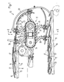
- FIGS. 1 and 2 In the device 10 shown, a feed conveyor 11 and a removal conveyor 12 and a deflection mechanism 13 arranged between them can be seen.
- the feed conveyor 11 effective in the direction of the arrow 14 has driver cams 16 fastened at regular intervals from one another on an endless, guided chain 15 indicated by dash-dotted lines, each of which pushes a printed product 17 in front of it.
- the mutual distance of the driver cams 16 from one another is smaller than the format of the printed products 17 measured in the direction of the arrow 14, so that their leading edge (here the cut edge or flower) overlaps the trailing edge (here the fold or collar) of the preceding printed product.
- the printed products 17 thus occur here in an ordered scale flow with a regular, so-called "scale spacing".
- the removal conveyor 12 effective in the direction of arrow 18 is constructed analogously.
- Driving cams 20 are fastened at intervals from one another to an endless, revolvingly driven and guided chain, which in turn push the now-turned printed products 17 (it will be come back to this later) at their trailing edge.
- the distances of the driver cams 20 from one another correspond to those of the driver cams 16 from one another and the speed of the chain 19 corresponds to that of the chain 15, regardless of the direction.
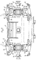
- the deflection device 13 - as can be seen in FIG. 2 - has two pairs of chains 21-21 and 22-22 rotating in parallel to one another, the deflection wheels 23, 24 (FIG. 1) arranged in pairs and in parallel axes and in between in upper rails 25, 25 'and lower rails 26, 26' are guided in a straight line.
- Each of the chain pairs 21-21 and 22-22 is equipped with a total of six outwardly projecting carriers 27 and 28, the spacing of which from one another - as seen in the straight-line sections of the chain pairs 21-21 and 22-22 - the distances between the driving cams 16 or 20 correspond from each other.
- Each of the carriers 17, 18 consists of two articulated couplers 29, 30 and 31, 32, which are articulated at their outer ends at 33 and 34 and at their inner ends at a distance from one another on the corresponding pair of chains 21-21 and 22- 22 are articulated.
- the carriers 27 and 28 are each provided with a gripper 35 or 36, which has a jaw 37 or 38 which is fixed with respect to the corresponding articulated coupling 29 or 31 and which is fixed to the fixed jaw 37 by springs 40 or 41 or 38 to, ie Has pivoted jaw 42 or 43 biased in the closed position.
- the pivotable jaws 42 and 43 are by means of a non-visible lever mechanism, of which only a tappet 42 ', 43', which is protruding from the side and is provided with rollers, can be seen from the closed position into the open position indicated by dash-dotted lines in FIG and controllable back.
- the parallel pairs of chains 21-21 and 22-22 are each driven via a sprocket 46 or 47 via chains, not shown, in synchronism with one another, at the same speed as the chains 15 and 19.
- the distance between the carriers 27 and that the carrier 28 corresponds to one another - as long as they are on the strand of the chain pairs 21-21 or on the straight line between the deflection wheels 23, 24 or 22-22 are - that of the driver cams 16 and 20 from each other.
- the grippers 35 and 36 as long as their carriers 27 and 28 on the rectilinear strands of the chain pairs 21-21 and 22-22 are absolutely synchronous with those from the feed conveyor 11 on a sliding table 48 (FIG. 1 above) deferred print products 17 run.
- the sliding table 48 is less wide than the printed products 17, so that they protrude on both sides.
- the grippers 35 and 36 are closed, as shown in FIG. l is shown at the top right next to section line II-II. In this way, they grasp the printed product 17 located in their area on its lateral edges.
- the deceleration phase of the carriers 27, 28 and thus the grippers 35, 36 begins. This deceleration phase continues until the The articulation point of the articulated coupling 29, 31 on the corresponding chain pair 21-21 or 22-22 has left the deflection wheel 23.
- the grippers 35, 36 thus run at the same speed as the conveyor 12 and the grippers can thus be opened, whereupon the corresponding printed product 17 is transferred to the conveyor 12.
- Fig. 1 the upper side of the printed products 17 accumulating on the feed conveyor 11 is indicated by a thick line.
- this side which was at the top lies at the bottom, but the scale formation present on the conveyor 11 has been preserved in the sense that the leading edge of each printed product overlaps the trailing edge of the preceding printed product 17 .
- Each printed product is therefore turned around turning axes parallel to the conveying direction and the original formation has been retained.
- the printed products 17 can also be produced with the leading bundle and the trailing flower on the feed conveyor 11 and can be carried away on the away conveyor.
- the embodiment outlined in FIG. 3 differs from the previously described embodiment primarily in that one and the same individual conveyor 51 serves as the feed conveyor and as the away conveyor.
- This is essentially like the one described in CH-PS 644.816 (largely identical in content to DE-OS 3 102 242.1 and US-PS 4,381,056) with a difference.
- This difference consists in the fact that its grippers 52 are coupled at regular intervals from one another via a coupling element 54 to the chain 53, which is only indicated, but at the same time each gripper is pivotably articulated on the coupling member 54 about a pivot pin 55 directed transversely to the chain 53.
- a roller 56 is arranged on the housing of each of the grippers 52, which are controlled in the open or closed position in the same way as in the abovementioned patents, and which cooperates with stationary scenes 57, 58, so that ultimately the scenes 57, 58 determine the pivoting position of the grippers 52 determine with respect to chain 53.
- the printed products 17 produced by the strand of the individual conveyor 51 appearing at the top in FIG. 3 in the same formation as in FIG. 1 are now taken over by an intermediate conveyor 59 constructed similarly to the feed conveyor 11 or the removal conveyor 12, the driver cams 60 of which are at a greater distance are attached to each other on the only indicated chain 61 as the mutual distance of the grippers 52 on the chain 53.
- the conveying speed of the intermediate conveyor 59 is so much higher than that of the individual conveyor 51 that one of the driving cams 60 always meets one of the grippers 52 .
- the driver cams 60 thus pull the pressure pro Products 17 from the mouth of the now opened grippers 52 and push them forward onto the sliding table 48, where they are taken over by the deflection mechanism 13, which is only shown schematically.
- the carriers 27, 28 which carry the grippers 35, 36 and protrude outwards from the chains 21-21, 22-22 are not formed here by two articulated couplers, but are fastened in a suitable manner to the associated chains 21-21, 22-22 that they protrude from them at right angles.
- the distance between the carriers 27, 28 corresponds to that of the driver cams 60 from one another and the rotational speed of the chains 21-21, 22-22 corresponds here to that of the intermediate conveyor 59.
- the grippers 35, 36 and the printed product 17 captured by them suddenly get a higher speed as soon as the corresponding carrier 27, 28 or its associated chains 21-21, 22-22 runs onto the deflection wheel 23, which in this case is smaller than the deflection wheel 24 is.
Landscapes
- Engineering & Computer Science (AREA)
- Mechanical Engineering (AREA)
- Discharge By Other Means (AREA)
- Registering Or Overturning Sheets (AREA)
- Separation, Sorting, Adjustment, Or Bending Of Sheets To Be Conveyed (AREA)
- Feeding Of Articles By Means Other Than Belts Or Rollers (AREA)
- Attitude Control For Articles On Conveyors (AREA)
- Control And Other Processes For Unpacking Of Materials (AREA)
Abstract
Description
Die vorliegende Erfindung betrifft ein Verfahren gemäss dem Oberbegriff des Patentanspruches 1 sowie eine Vorrichtung gemäss dem Oberbegriff des Patentanspruches 5. Namentlich bei in Schuppenformationen anfallenden Druckprodukten, insbesondere Zeitungen oder Zeitungsbestandteilen, kommt es oft vor, dass die im Schuppenstrom unten liegende Seite des Druckproduktes für die weitere Verarbeitung, beispielsweise für ein Zusammenführen einzelner unterschiedlicher Druckprodukte zu einem Fertigprodukt, oben liegen sollte, damit im Fertigprodukt die einzelnen Bestandteile in bezug aufeinander richtig orientiert sind.The present invention relates to a method according to the preamble of patent claim 1 and a device according to the preamble of patent claim 5. In particular in the case of printed products resulting in scale formations, in particular newspapers or newspaper components, it often happens that the side of the printed product lying in the scale pattern below is suitable for the Further processing, for example for merging individual different printed products into a finished product, should be on top so that the individual components in the finished product are correctly oriented with respect to one another.
Um ein solches Wenden um zur Förderrichtung parallele Achsen zu bewirken, ist es bekannt, die Schuppenformation durch geeignete Führungen in Förderrichtung um 180 zu verwinden. Dabei geht aber die klassische Schuppenformation, bei der die vorlaufende Kante jedes Druckprodukes die nachlaufende Kante des vorangehenden Druckproduktes überlappt, verloren. Nach einem Verwinden eines Schuppenstromes um 180 präsentiert sich dieser Schuppenstrom so, dass die nachlaufende Kante jedes Druckproduktes die vorlaufende Kante des nachfolgenden Druckproduktes überlappt. Dies ist für eine weitere Verarbeitung unzweckmässig.In order to effect such a turning around axes parallel to the conveying direction, it is known to twist the scale formation by suitable guides in the conveying direction by 180. However, the classic scale formation, in which the leading edge of each printed product overlaps the trailing edge of the preceding printed product, is lost. After twisting a shingled stream around 180, this shingled stream presents itself in such a way that the trailing edge of each printed product overlaps the leading edge of the following printed product. This is unsuitable for further processing.
Es ist daher ein Zweck der Erfindung, ein Verfahren und eine Vorrichtung der eingangs genannten Art zu schaffen, welche ein solches Wenden ohne ein Verwinden der Bewegungsbahn gestattet und dabei - wenn gewünscht - die ursprüngliche Schuppenformation erhalten bleibt.It is therefore a purpose of the invention to provide a method and a device of the type mentioned at the outset which permit such turning without twisting the trajectory and, if desired, retain the original scale formation.
Dementsprechend weist das vorgeschlagene Verfahren die im Kennzeichen des Patentanspruches 1 angegebenen Schritte und die Vorrichtung die im Kennzeichen des Patentanspruches 5 definierten Merkmale auf.Accordingly, the proposed method has the steps specified in the characterizing part of patent claim 1 and the device has the features defined in the characterizing part of patent claim 5.
Bevorzugte Ausführungsformen des Verfahrens und der Vorrichtung sind den abhängigen Ansprüchen 2 bis 4 bzw. 6 bis 11 zu entnehmen.Preferred embodiments of the method and the device can be found in the dependent claims 2 to 4 and 6 to 11.
Nachstehend ist die Erfindung rein beispielsweise anhand der Zeichnung näher erläutert. Es zeigt:
- Fig. 1 eine Seitenansicht einer Vorrichtung,
- Fig. 2 einen etwas schematisierten Schnitt etwa längs der Linie II-II der Fig. l, und
- Fig. 3 in sehr schematisierter Darstellungsweise eine Ausführungsvariante.
- 1 is a side view of a device,
- Fig. 2 is a somewhat schematic section approximately along the line II-II of Fig. 1, and
- Fig. 3 in a very schematic representation of an embodiment.
Es sei zuerst auf die Fig. 1 und 2 Bezug genommen. Bei der dargestellten Vorrichtung 10 erkennt man einen Zuförderer 11 und einen Wegförderer 12 und einen dazwischen angeordneten Umlenkmechanismus 13.Reference is first made to FIGS. 1 and 2. In the
Der in Richtung des Pfeiles 14 wirksame Zuförderer 11 weist in regelmässigen Abständen voneinander an einer strichpunktiert angedeuteten, endlosen, geführten Kette 15 befestigte Mitnehmernocken 16 auf, von denen jeder ein Druckprodukt 17 vor sich her stösst. Dabei ist der gegenseitige Abstand der Mitnehmernocken 16 voneinander geringer als das in Richtung des Pfeiles 14 gemessene Format der Druckprodukte 17, so dass deren vorlaufende Kante (hier die Schnittkante oder Blume) die nachlaufende Kante (hier der Falz oder Bund) des vorangehenden Druckproduktes überlappt. Die Druckprodukte 17 fallen hier also in einem geordneten Schuppenstrom mit einem regelmässigen, sogenannten "Schuppenabstand" an.The feed conveyor 11 effective in the direction of the
Analog ist der in Richtung des Pfeiles 18 wirksame Wegförderer 12 aufgebaut. An einer endlosen, umlaufend angetriebenen und geführten Kette 19 sind in Abständen voneinander Mitnehmernocken 20 befestigt, die die nun gewendeten Druckprodukte 17 (darauf wird noch zurückzukommen sein) wiederum an deren nachlaufenden Kante vor sich her stossen. Die Abstände der Mitnehmernocken 20 voneinander entsprechen jenen der Mitnehmernocken 16 voneinander und die Geschwindigkeit der Kette 19 entspricht - abgesehen von der Richtung - jener der Kette 15.The removal conveyor 12 effective in the direction of arrow 18 is constructed analogously.
Die Umlenkvorrichtung 13 weist - wie der Fig. 2 zu entnehmen ist - zwei Paare von parallel zueinander umlaufenden Ketten 21-21 und 22-22 auf, die um paarweise und parallelachsig angeordnete Umlenkräder 23, 24 (Fig. 1) und dazwischen in oberen Schienen 25, 25' und unteren Schienen 26, 26' geradlinig geführt sind.The deflection device 13 - as can be seen in FIG. 2 - has two pairs of chains 21-21 and 22-22 rotating in parallel to one another, the
Jedes der Kettenpaare 21-21 und 22-22 ist mit insgesamt sechs nach aussen abstehenden Trägern 27 bzw. 28 bestückt, deren Abstand voneinander - in den geradlinigen Abschnitten der Kettenpaare 21-21 und 22-22 gesehen - den Abständen der Mitnehmernocken 16 oder 20 voneinander entsprechen. Jeder der Träger 17, 18 besteht aus zwei Gelenkkoppeln 29, 30 bzw. 31, 32, die an ihren äusseren Enden bei 33 bzw. 34 aneinander angelenkt sind und an ihren inneren Enden im Abstand voneinander am entsprechenden Kettenpaar 21-21 bzw. 22-22 angelenkt sind.Each of the chain pairs 21-21 and 22-22 is equipped with a total of six outwardly projecting
An ihren äusseren Enden sind die Träger 27 und 28 mit je einem Greifer 35 bzw. 36 versehen, der eine bezüglich der entsprechenden Gelenkkoppeln 29 bzw. 31 feste Backe 37 bzw. 38 aufweist und eine durch Federn 40 bzw. 41 auf die feste Backe 37 bzw. 38 zu, d.h. in Schliesslage vorgespannte schwenkbare Backe 42 bzw. 43 aufweist. Die schwenkbaren Backen 42 und 43 sind über ein nicht sichtbares Hebelgetriebe, von dem nur ein seitlieh abstehender, mit Rollen versehener Stössel 42', 43' sichtbar ist, mittels ortsfesten Kulissen 44, 45 von der Schliesslage in die in Fig. 2 strichpunktiert angegebene Offenlage und zurück steuerbar.At their outer ends, the
Die parallel zueinander umlaufenden Kettenpaare 21-21 und 22-22 sind je über ein Kettenrad 46 bzw. 47 über nicht dargestellte Ketten genau synchron zueinander angetrieben und zwar mit der gleichen Geschwindigkeit wie die Ketten 15 und 19. Der Abstand der Träger 27 voneinander und jener der Träger 28 voneinander entspricht - solange diese sich auf sich auf dem geradlinig zwischen-den Umlenkrädern 23, 24 befindlichen Trum der Kettenpaare 21-21 bzw. 22-22 befinden - jenem der Mitnehmernocken 16 bzw. 20 voneinander.The parallel pairs of chains 21-21 and 22-22 are each driven via a
Daraus geht hervor, dass die Greifer 35 und 36, solange ihre Träger 27 bzw. 28 auf den geradlinigen Trumen der Kettenpaare 21-21 bzw. 22-22 sind absolut synchron mit den vom Zuförderer 11 auf einen Gleittisch 48 (Fig. 1 oben) aufgeschobenen Druckprodukte 17 laufen. Der Gleittisch 48 ist weniger breit als die Druckprodukte 17, so dass diese zu beiden Seiten vorstehen. Kurz bevor einer der Träger 27, 28 bzw. seine Gelenkkoppel 30 bzw. 32 mit ihrem Anlenkpunkt an dem Kettenpaar 21-21 bzw. 22-22 beginnt auf das Umlenkrad 23 aufzulaufen, werden die Greifer 35 und 36 geschlossen, wie dies in Fig. l oben rechts neben der Schnittlinie II-II gezeigt ist. Damit erfassen sie das in ihrem Bereich befindliche Druckprodukt 17 an seinem seitlichen Rändern. Da nun die Träger 27, 28 von den Kettenpaaren 21-21 bzw. 22-22 nach aussen abstehen, erfährt ihr äusseres Ende bzw. der dort vorhandene Greifer eine Beschleunigung. Die Greifer 35, 36 werden dabei so lange beschleunigt, bis die Anlenkpunkte sowohl der Gelenkkoppeln 30 bzw. 32 als auch der Gelenkkoppeln 29 bzw. 31 an den entsprechenden Kettenpaaren 21-21 bzw. 22-22 auf dem Umlenkrad sind. Dadurch werden die Druckprodukte 17 vereinzelt und - gehalten durch die Greifer 35, 36 - einzeln um eine etwa der Drehachse des Umlenkrades 23 entsprechende Umlenkachse umgelenkt.It can be seen from this that the
Um die Druckprodukte 17 während dieses Umlenkvorganges zu stützen und/oder daran zu hindern wegen der Fliehkraft Schaden zu nehmen, ist einerseits eine etwa der Flugbahn der Greifer 35, 36 folgende, zwischen diesen angeordnete Walzenbahn 49 vorgesehen und andererseits eine der Flugbahn der Greifer 35, 36 aussen herum folgende Führungsschiene 50.In order to support the printed
Sobald der Anlenkpunkt der Gelenkkoppeln 30 bzw. 32 an den entsprechenden Kettenpaaren 21-21 und 22-22 das Umlenkrad verlässt, beginnt die Verzögerungsphase der Träger 27, 28 und damit der Greifer 35, 36. Diese Verzögerungsphase hält so lange an, bis auch der Anlenkpunkt der Gelenkkoppeln 29, 31 an dem entsprechenden Kettenpaar 21-21 bzw. 22-22 das Umlenkrad 23 verlassen hat. Damit laufen die Greifer 35, 36 wieder gleich schnell wie der Wegförderer 12 und die Greifer können somit geöffnet werden, worauf das entsprechende Druckprodukt 17 dem Wegförderer 12 übergeben wird.As soon as the pivot point of the articulated
In Fig. 1 ist die obere Seite der auf dem Zuförderer 11 anfallenden Druckprodukte 17 durch einen dicken Strich angedeutet. Wenn das Druckprodukt den Wegförderer 12 erreicht hat, liegt diese oben gewesene Seite unten, wobei aber die auf dem Zuförderer 11 vorhandene Schuppenformation in dem Sinne auf dem Wegförderer 12 erhalten geblieben ist, dass die vorlaufende Kante jedes Druckproduktes die nachlaufende Kante des vorangehenden Druckproduktes 17 überlappt. Jedes Druckprodukt ist also um zur Förderrichtung parallele Wendeachsen gewendet und die ursprüngliche Formation ist beibehalten worden. Selbstverständlich können die Druckprodukte 17 auch mit vorlaufendem Bund und nachlaufender Blume auf dem Zuförderer 11 anfallen und auf dem Wegförderer weggeführt werden.In Fig. 1, the upper side of the printed
Die in Fig. 3 skizzierte Ausführungsform unterscheidet sich von der bisher beschriebenen Ausführungsform vor allem dadurch, dass als Zuförderer und als Wegförderer ein und derselbe Einzelförderer 51 dient. Dieser ist im wesentlichen wie derinderCH-PS 644.816 (weitgehend inhaltsgleich mit der DE-OS 3 102 242.1 und der US-PS 4,381,056) beschriebene Einzelförderer mit einem Unterschied aufgebaut. Dieser Unterschied besteht darin, dass seine Greifer 52 zwar in regelmässigen Abständen voneinander über ein Kopplungselement 54 an die nur angedeutete Kette 53 gekoppelt sind, aber jeder Greifer ist zugleich um einen quer zur Kette 53 gerichteten Schwenkzapfen 55 schwenkbar am Kopplungsglied 54 angelenkt. Am Gehäuse jedes der im übrigen gleich wie in den genannten Patentschriften in Offen- bzw. Schliesslage gesteuerten Greifer 52 ist ausserdem eine Rolle 56 angeordnet, die mit ortsfesten Kulissen 57, 58 zusammenwirkt, so dass letztlich die Kulissen 57, 58 die Schwenklage der Greifer 52 in bezug auf die Kette 53 bestimmen.The embodiment outlined in FIG. 3 differs from the previously described embodiment primarily in that one and the same individual conveyor 51 serves as the feed conveyor and as the away conveyor. This is essentially like the one described in CH-PS 644.816 (largely identical in content to DE-OS 3 102 242.1 and US-PS 4,381,056) with a difference. This difference consists in the fact that its
Die von dem in Fig. 3 oben erscheinenden Trum des Einzelförderers 51 in der gleichen Formation wie in Fig. 1 anfallenden Druckprodukte 17 werden nun von einem ähnlich wie der Zuförderer 11 oder der Wegförderer 12 gebaute Zwischenförderer 59 übernommen, dessen Mitnehmernocken 60 in einem grösseren Abstand voneinander an der nur angedeuteten Kette 61 befestigt sind als der gegenseitige Abstand der Greifer 52 an der Kette 53. Dagegen ist die Fördergeschwindigkeit des Zwischenförderers 59 um so viel höher als jene des Einzelförderers 51, dass stets einer der Mitnehmernocken 60 mit einem der Greifer 52 zusammentrifft. Damit ziehen die Mitnehmernocken 60 die Druckprodukte 17 aus dem Maul der nun geöffneten Greifer 52 und schieben sie vor sich hin auf den Gleittisch 48, wo sie vom nur schematisch dargestellten Umlenkmechanismus 13 übernommen werden. Die die Greifer 35, 36 tragenden und von den Ketten 21-21, 22-22 nach aussen abstehenden Träger 27, 28 sind hier nicht durch zwei Gelenkkoppeln gebildet, sondern auf geeignete Weise so an den zugeordneten Ketten 21-21, 22-22 befestigt, dass sie von diesen rechtwinklig abstehen.The printed
Der Abstand der Träger 27, 28 voneinander entspricht jenem der Mitnehmernocken 60 voneinander und die Umlaufgeschwindigkeit der Ketten 21-21, 22-22 entspricht hier jener des Zwischenförderers 59.The distance between the
Damit erhalten die Greifer 35, 36 und das von diesen erfassten Druckprodukt 17 plötzlich eine höhere Geschwindigkeit, sobald der entsprechende Träger 27, 28 bzw. dessen zugeordnete Ketten 21-21, 22-22 auf das Umlenkrad 23 aufläuft, das hier kleiner als das Umlenkrad 24 ist.Thus, the
Deswegen sind die geradlinigen Trume der Ketten 21-21, 22-22 zwischen den Rädern 23 und 24 nicht parallel zueinander. Das in Fig. 3 unten erscheinende "rücklaufende Trum" der Ketten 21-21 und 22-22 führt im wesentlichen radial auf das Umlenkrad 62 des Einzelförderers 51 zu, an dem die leeren und noch offenen Greifer 52 durch die Kulissen 57, 58 inzwischen in eine rechtwinklig von der Kette 53 abstehende Schwenklage gebracht worden sind. Dadurch wird nun die vorlaufende Kante der Druckprodukte 17 von den Greifern 52 erfasst, und diese werden dann am unteren Trum des Einzelförderers 51 hängend weggeführt. Würden die weggeführten Druckprodukte 17 über einen gestrichelt angedeuteten Gleittisch 63 geschleift, wird klar, dass die Formation, in der die Druckprodukte 17 zugeführt wurden praktisch dieselbe geblieben ist, d.h. die "vorlaufende" Kante (hier die Blume) überlappt die nachlaufende Kante (hier den Bund) des vorangehenden Druckproduktes. Auch sind die Druckprodukte durch den Umlenkmechanismus gewendet worden, denn die mit einem kurzen Teil bezeichneten oberen Seiten der zugeführten Druckprodukte liegen nun in der "Quasi"-Schuppenformation auf dem Gleittisch 63 unten. Im Zuge dieses Wendens haben aber auch die Greifer 52 in dem Sinne gewechselt, dass sie beim Zuführen der Druckprodukte 17 deren nachlaufende Kanten (hier den Bund) ergriffen haben und beim Wegführen deren gegenüberliegende Kante, hier die Blume.Therefore, the straight lines of the chains 21-21, 22-22 between the
Claims (11)
Priority Applications (1)
| Application Number | Priority Date | Filing Date | Title |
|---|---|---|---|
| AT87105170T ATE46489T1 (en) | 1986-04-18 | 1987-04-08 | METHOD AND DEVICE FOR TURNING CONTINUOUSLY CONVEYED FLAT STRUCTURES. |
Applications Claiming Priority (2)
| Application Number | Priority Date | Filing Date | Title |
|---|---|---|---|
| CH1579/86 | 1986-04-18 | ||
| CH157986 | 1986-04-18 |
Publications (2)
| Publication Number | Publication Date |
|---|---|
| EP0242702A1 true EP0242702A1 (en) | 1987-10-28 |
| EP0242702B1 EP0242702B1 (en) | 1989-09-20 |
Family
ID=4213718
Family Applications (1)
| Application Number | Title | Priority Date | Filing Date |
|---|---|---|---|
| EP87105170A Expired EP0242702B1 (en) | 1986-04-18 | 1987-04-08 | Method and device for turning continually arriving flat products |
Country Status (6)
| Country | Link |
|---|---|
| US (1) | US4896874A (en) |
| EP (1) | EP0242702B1 (en) |
| JP (1) | JP2538243B2 (en) |
| AT (1) | ATE46489T1 (en) |
| CA (1) | CA1282365C (en) |
| DE (1) | DE3760577D1 (en) |
Cited By (4)
| Publication number | Priority date | Publication date | Assignee | Title |
|---|---|---|---|---|
| EP0330868A1 (en) * | 1988-03-03 | 1989-09-06 | Ferag AG | Process and device for conveying away printed products fed in a shingled formation |
| EP0754642A3 (en) * | 1995-07-20 | 1997-08-27 | Heidelberger Druckmasch Ag | Device for delivering sheet-like products |
| CH692617A5 (en) * | 1998-02-27 | 2002-08-30 | Ferag Ag | Apparatus for processing flexible, sheet-like products. |
| EP2243734A1 (en) * | 2009-04-23 | 2010-10-27 | Müller Martini Holding AG | Method for turning printed products transported on a conveyor path in a supply stream |
Families Citing this family (10)
| Publication number | Priority date | Publication date | Assignee | Title |
|---|---|---|---|---|
| SE468765B (en) * | 1991-05-24 | 1993-03-15 | Wamag Idab Ab | SIDOGRIC TRANSPORT |
| US5451040A (en) * | 1993-05-03 | 1995-09-19 | R.R. Donnelley & Sons Co. | Signature feeder for a binding line |
| DE59505081D1 (en) * | 1994-11-18 | 1999-03-25 | Grapha Holding Ag | Process for the production of adhesive-bound books, brochures or the like products |
| WO1996032351A1 (en) * | 1995-04-11 | 1996-10-17 | Grapha-Holding Ag | Process and device for conveying a stream of print shop products |
| AU755468B2 (en) | 1998-06-15 | 2002-12-12 | Ferag Ag | Apparatus for processing flexible, sheet-like products |
| DE19837095A1 (en) * | 1998-08-17 | 2000-02-24 | Weitmann & Konrad Fa | Mechanism for balancing of free inertia forces in internal combustion engine of motor vehicle has drive shaft running parallel to hollow balance shaft and extending concentrically through it |
| DE59903526D1 (en) * | 1998-09-04 | 2003-01-09 | Ferag Ag | Conveying device for flexible, flat objects resulting in a scale formation |
| EP1227052B1 (en) * | 2001-01-24 | 2004-08-11 | Ferag AG | Method and device for changing the gripping position of flat objects, conveyed by grippers |
| CH705026A2 (en) * | 2011-05-16 | 2012-11-30 | Ferag Ag | Apparatus and method for generating an uninterrupted imbricated stream of flat product units, in particular printed products. |
| CN116177270B (en) * | 2023-05-04 | 2023-07-07 | 常州宏业包装材料有限公司 | Corrugated board turnover machine |
Citations (2)
| Publication number | Priority date | Publication date | Assignee | Title |
|---|---|---|---|---|
| DE3417053A1 (en) * | 1983-06-09 | 1984-12-13 | Ferag AG, Hinwil, Zürich | METHOD AND DEVICE FOR THE INTERMEDIATE STORAGE OF PRINTED PRODUCTS INCLUDING IN A DOMESTIC FLOW, LIKE NEWSPAPERS, MAGAZINES OR THE LIKE. |
| DE3404459A1 (en) * | 1984-02-08 | 1985-08-14 | Frankenthal Ag Albert | METHOD AND DEVICE FOR DISPLAYING ARC-SHAPED PRODUCTS IN THE FORM OF A SHED FLOW |
Family Cites Families (7)
| Publication number | Priority date | Publication date | Assignee | Title |
|---|---|---|---|---|
| US3642274A (en) * | 1970-08-07 | 1972-02-15 | Francis Walter Herrington | Sheet-supporting assembly for an inverter roll |
| CH644816A5 (en) * | 1980-02-08 | 1984-08-31 | Ferag Ag | CONVEYING DEVICE, PARTICULAR FOR PRINTED PRODUCTS, WITH GRIPPERS ANCHORED ON A CIRCULAR ZUGORGAN. |
| CH652105A5 (en) * | 1981-07-15 | 1985-10-31 | Grapha Holding Ag | METHOD AND DEVICE FOR STORING PRINTED SHEETS. |
| CH657114A5 (en) * | 1982-06-02 | 1986-08-15 | Ferag Ag | METHOD AND APPARATUS FOR PROCESSING IN A SHED FORMATION OCCURRING flat products, ESPECIALLY PRINTED PRODUCTS. |
| CH660171A5 (en) * | 1983-06-09 | 1987-03-31 | Ferag Ag | METHOD AND DEVICE FOR THE INTERMEDIATE STORAGE OF PRINTED PRODUCTS INCLUDING IN A DOMESTIC FLOW, LIKE NEWSPAPERS, MAGAZINES OR THE LIKE. |
| JPS606548A (en) * | 1983-06-24 | 1985-01-14 | Kitagawa Seiki Kk | Sheet inversion mechanism |
| US4566687A (en) * | 1984-05-11 | 1986-01-28 | Custom-Bilt Machinery, Inc. | Transferring newspapers or the like from a moving belt to a series of clamps |
-
1987
- 1987-04-08 AT AT87105170T patent/ATE46489T1/en active
- 1987-04-08 EP EP87105170A patent/EP0242702B1/en not_active Expired
- 1987-04-08 DE DE8787105170T patent/DE3760577D1/en not_active Expired
- 1987-04-13 US US07/037,960 patent/US4896874A/en not_active Expired - Fee Related
- 1987-04-14 JP JP62091843A patent/JP2538243B2/en not_active Expired - Lifetime
- 1987-04-16 CA CA000534894A patent/CA1282365C/en not_active Expired - Fee Related
Patent Citations (2)
| Publication number | Priority date | Publication date | Assignee | Title |
|---|---|---|---|---|
| DE3417053A1 (en) * | 1983-06-09 | 1984-12-13 | Ferag AG, Hinwil, Zürich | METHOD AND DEVICE FOR THE INTERMEDIATE STORAGE OF PRINTED PRODUCTS INCLUDING IN A DOMESTIC FLOW, LIKE NEWSPAPERS, MAGAZINES OR THE LIKE. |
| DE3404459A1 (en) * | 1984-02-08 | 1985-08-14 | Frankenthal Ag Albert | METHOD AND DEVICE FOR DISPLAYING ARC-SHAPED PRODUCTS IN THE FORM OF A SHED FLOW |
Cited By (8)
| Publication number | Priority date | Publication date | Assignee | Title |
|---|---|---|---|---|
| EP0330868A1 (en) * | 1988-03-03 | 1989-09-06 | Ferag AG | Process and device for conveying away printed products fed in a shingled formation |
| US4953847A (en) * | 1988-03-03 | 1990-09-04 | Ferag Ag | Method of and apparatus for outfeeding printed products arriving in an imbricated formation |
| EP0754642A3 (en) * | 1995-07-20 | 1997-08-27 | Heidelberger Druckmasch Ag | Device for delivering sheet-like products |
| CH692617A5 (en) * | 1998-02-27 | 2002-08-30 | Ferag Ag | Apparatus for processing flexible, sheet-like products. |
| EP2243734A1 (en) * | 2009-04-23 | 2010-10-27 | Müller Martini Holding AG | Method for turning printed products transported on a conveyor path in a supply stream |
| US8167112B2 (en) | 2009-04-23 | 2012-05-01 | Mueller Martini Holding Ag | Method and arrangement to turn print products conveyed in a flow along a conveying path |
| AU2010201530B2 (en) * | 2009-04-23 | 2014-05-01 | Muller Martini Holding Ag | Method to turn printed products transported in a transport stream on a transporting path |
| AU2010201530A8 (en) * | 2009-04-23 | 2014-05-15 | Muller Martini Holding Ag | Method to turn printed products transported in a transport stream on a transporting path |
Also Published As
| Publication number | Publication date |
|---|---|
| ATE46489T1 (en) | 1989-10-15 |
| DE3760577D1 (en) | 1989-10-26 |
| CA1282365C (en) | 1991-04-02 |
| JP2538243B2 (en) | 1996-09-25 |
| EP0242702B1 (en) | 1989-09-20 |
| US4896874A (en) | 1990-01-30 |
| JPS62255340A (en) | 1987-11-07 |
Similar Documents
| Publication | Publication Date | Title |
|---|---|---|
| EP1232978B1 (en) | Transport device for gathering and transporting printed sheets laid astride on a first transport chain | |
| EP0013920B1 (en) | Device for feeding a conveyor with flat objects in shingled formation, in particular printed products | |
| CH630583A5 (en) | DEVICE FOR MOVING AWAY OF FLAT PRODUCTS INCLUDING IN A DOMESTIC FLOW, IN PARTICULAR PRINTED PRODUCTS. | |
| EP0208081B1 (en) | Method and device for opening eccentrically folded printing products | |
| DE19731846A1 (en) | Device for transporting flat products to further processing facilities or delivery stations | |
| EP0305671B1 (en) | Conveyor for prints, and use of the conveyor | |
| EP0242702B1 (en) | Method and device for turning continually arriving flat products | |
| EP0368009B1 (en) | Method and device for advancing printed articles | |
| DE3145491A1 (en) | "DEVICE FOR LAYING UP SINGLE AREA PRODUCTS, IN PARTICULAR PRINTED PRODUCTS" | |
| EP0564812B1 (en) | Method and device for opening folded printing products | |
| EP0754642B1 (en) | Method and device for delivering sheet-like products | |
| EP0407763B1 (en) | Device for removing printed products from a rotating driven star wheel of a printing machine | |
| EP0312755B1 (en) | Conveyor for continuously supplied flat products, in particular prints | |
| EP0300171B1 (en) | Device for transporting flat products, in particular printed products | |
| DE2832660C3 (en) | Device for group-wise division of workpieces conveyed on top of each other in shingled form | |
| EP0218804B1 (en) | Device for taking over and transferring folded sheets from a conveyor | |
| EP0551055A2 (en) | Method and device for gathering printed matter | |
| EP0307889A2 (en) | Device for delivering prints from the paddle wheels of a folding apparatus | |
| EP0647582A1 (en) | Device for opening and further conveying printed products | |
| EP0518064B1 (en) | Method and apparatus for handling of printed products | |
| EP1072546B1 (en) | Conveyer for collating and processing printed sheets | |
| EP0300170B1 (en) | Method and device for separating products in overlapping streams, in particular printed products | |
| DE2104440C3 (en) | Device for depositing flat, flexible workpieces, e.g. pieces of tubing, which are moved one behind the other without overlapping | |
| EP2017209B1 (en) | Method and device for transferring printing products in shingled formation to an endless conveyor carrying grippers | |
| DE1561141B2 (en) | DEVICE FOR INSERTING INSERTS INTO FOLDED PRINT PRODUCTS |
Legal Events
| Date | Code | Title | Description |
|---|---|---|---|
| PUAI | Public reference made under article 153(3) epc to a published international application that has entered the european phase |
Free format text: ORIGINAL CODE: 0009012 |
|
| AK | Designated contracting states |
Kind code of ref document: A1 Designated state(s): AT CH DE FR GB IT LI SE |
|
| 17P | Request for examination filed |
Effective date: 19871009 |
|
| 17Q | First examination report despatched |
Effective date: 19880718 |
|
| GRAA | (expected) grant |
Free format text: ORIGINAL CODE: 0009210 |
|
| AK | Designated contracting states |
Kind code of ref document: B1 Designated state(s): AT CH DE FR GB IT LI SE |
|
| REF | Corresponds to: |
Ref document number: 46489 Country of ref document: AT Date of ref document: 19891015 Kind code of ref document: T |
|
| ET | Fr: translation filed | ||
| REF | Corresponds to: |
Ref document number: 3760577 Country of ref document: DE Date of ref document: 19891026 |
|
| GBT | Gb: translation of ep patent filed (gb section 77(6)(a)/1977) | ||
| ITF | It: translation for a ep patent filed | ||
| PLBE | No opposition filed within time limit |
Free format text: ORIGINAL CODE: 0009261 |
|
| STAA | Information on the status of an ep patent application or granted ep patent |
Free format text: STATUS: NO OPPOSITION FILED WITHIN TIME LIMIT |
|
| 26N | No opposition filed | ||
| ITTA | It: last paid annual fee | ||
| EAL | Se: european patent in force in sweden |
Ref document number: 87105170.2 |
|
| PGFP | Annual fee paid to national office [announced via postgrant information from national office to epo] |
Ref country code: FR Payment date: 19960318 Year of fee payment: 10 |
|
| PGFP | Annual fee paid to national office [announced via postgrant information from national office to epo] |
Ref country code: SE Payment date: 19960321 Year of fee payment: 10 |
|
| PGFP | Annual fee paid to national office [announced via postgrant information from national office to epo] |
Ref country code: AT Payment date: 19960322 Year of fee payment: 10 |
|
| PG25 | Lapsed in a contracting state [announced via postgrant information from national office to epo] |
Ref country code: AT Effective date: 19970408 |
|
| PG25 | Lapsed in a contracting state [announced via postgrant information from national office to epo] |
Ref country code: SE Effective date: 19970409 |
|
| PG25 | Lapsed in a contracting state [announced via postgrant information from national office to epo] |
Ref country code: FR Free format text: LAPSE BECAUSE OF NON-PAYMENT OF DUE FEES Effective date: 19971231 |
|
| EUG | Se: european patent has lapsed |
Ref document number: 87105170.2 |
|
| REG | Reference to a national code |
Ref country code: FR Ref legal event code: ST |
|
| REG | Reference to a national code |
Ref country code: GB Ref legal event code: IF02 |
|
| PGFP | Annual fee paid to national office [announced via postgrant information from national office to epo] |
Ref country code: GB Payment date: 20040331 Year of fee payment: 18 |
|
| PGFP | Annual fee paid to national office [announced via postgrant information from national office to epo] |
Ref country code: DE Payment date: 20040408 Year of fee payment: 18 |
|
| PGFP | Annual fee paid to national office [announced via postgrant information from national office to epo] |
Ref country code: CH Payment date: 20040426 Year of fee payment: 18 |
|
| REG | Reference to a national code |
Ref country code: CH Ref legal event code: PFA Owner name: FERAG AG Free format text: FERAG AG#ZUERICHSTRASSE 74#8340 HINWIL (CH) -TRANSFER TO- FERAG AG#PATENTABTEILUNG Z. H. MARKUS FELIX ZUERICHSTRASSE 74#8340 HINWIL (CH) |
|
| PG25 | Lapsed in a contracting state [announced via postgrant information from national office to epo] |
Ref country code: IT Free format text: LAPSE BECAUSE OF NON-PAYMENT OF DUE FEES;WARNING: LAPSES OF ITALIAN PATENTS WITH EFFECTIVE DATE BEFORE 2007 MAY HAVE OCCURRED AT ANY TIME BEFORE 2007. THE CORRECT EFFECTIVE DATE MAY BE DIFFERENT FROM THE ONE RECORDED. Effective date: 20050408 Ref country code: GB Free format text: LAPSE BECAUSE OF NON-PAYMENT OF DUE FEES Effective date: 20050408 |
|
| PG25 | Lapsed in a contracting state [announced via postgrant information from national office to epo] |
Ref country code: LI Free format text: LAPSE BECAUSE OF NON-PAYMENT OF DUE FEES Effective date: 20050430 Ref country code: CH Free format text: LAPSE BECAUSE OF NON-PAYMENT OF DUE FEES Effective date: 20050430 |
|
| PG25 | Lapsed in a contracting state [announced via postgrant information from national office to epo] |
Ref country code: DE Free format text: LAPSE BECAUSE OF NON-PAYMENT OF DUE FEES Effective date: 20051101 |
|
| REG | Reference to a national code |
Ref country code: CH Ref legal event code: PL |
|
| GBPC | Gb: european patent ceased through non-payment of renewal fee |
Effective date: 20050408 |