EP0242584B1 - Device for the mechanical decoupling of a pipeline system - Google Patents
Device for the mechanical decoupling of a pipeline system Download PDFInfo
- Publication number
- EP0242584B1 EP0242584B1 EP87103788A EP87103788A EP0242584B1 EP 0242584 B1 EP0242584 B1 EP 0242584B1 EP 87103788 A EP87103788 A EP 87103788A EP 87103788 A EP87103788 A EP 87103788A EP 0242584 B1 EP0242584 B1 EP 0242584B1
- Authority
- EP
- European Patent Office
- Prior art keywords
- pipe
- piping
- fixed point
- piping system
- clamps
- Prior art date
- Legal status (The legal status is an assumption and is not a legal conclusion. Google has not performed a legal analysis and makes no representation as to the accuracy of the status listed.)
- Expired - Lifetime
Links
- 239000000463 material Substances 0.000 description 3
- 238000012360 testing method Methods 0.000 description 3
- 238000010438 heat treatment Methods 0.000 description 2
- 239000011150 reinforced concrete Substances 0.000 description 2
- 229910000831 Steel Inorganic materials 0.000 description 1
- 238000004378 air conditioning Methods 0.000 description 1
- 238000003287 bathing Methods 0.000 description 1
- 238000010276 construction Methods 0.000 description 1
- 238000004519 manufacturing process Methods 0.000 description 1
- 239000010959 steel Substances 0.000 description 1
- 238000009423 ventilation Methods 0.000 description 1
Images

Classifications
-
- F—MECHANICAL ENGINEERING; LIGHTING; HEATING; WEAPONS; BLASTING
- F16—ENGINEERING ELEMENTS AND UNITS; GENERAL MEASURES FOR PRODUCING AND MAINTAINING EFFECTIVE FUNCTIONING OF MACHINES OR INSTALLATIONS; THERMAL INSULATION IN GENERAL
- F16L—PIPES; JOINTS OR FITTINGS FOR PIPES; SUPPORTS FOR PIPES, CABLES OR PROTECTIVE TUBING; MEANS FOR THERMAL INSULATION IN GENERAL
- F16L3/00—Supports for pipes, cables or protective tubing, e.g. hangers, holders, clamps, cleats, clips, brackets
Definitions
- the invention relates to a device for the mechanical decoupling of a pipeline system, which has at least one connecting pipe piece, with which straight pipe sections of different directions are connected starting from a connection point, pipelines of the pipeline system being connected to a building at the same distances depending on the load capacity of the pipes Brackets are stored and, so that vibrations of the piping system can be calculated, are held immovably by at least one fixed point bracket.
- a fixed point is required for the mechanical decoupling of a pipeline system.
- a benchmark is known for example from "Dubbei: Taschenbuch für den Maschinenbau, Springer Verlag, 1981". The mechanical structure of such a fixed point is not described there.
- a suitable benchmark for a piping system is also known from "Klinger paperback for heating, ventilation and bathing technicians, Carl Marhold Verlag, 1968".
- a commercially available benchmark is mentioned there.
- This fixed point clamp is characterized by a large, inert mass.
- a known device for the mechanical decoupling of a pipeline system consequently consists of a complex, heavy fixed point fitting, e.g. made of steel, which is anchored in the reinforced concrete structure of a building and comprises a pipe of the piping system over a certain length.
- a fixed point fitting ensures that the pipeline at the fixed point is not deflected even by the greatest possible external forces.
- the invention has for its object to develop a device for the mechanical decoupling of a piping system, which manages with simple and lightweight brackets for the piping and still ensures a fixed point necessary for the calculation of the piping system.
- the work and material costs should be significantly reduced compared to the use of fixed point fittings.
- brackets are, without exception, commercially available pipe clamps, that three pipe clamps are arranged in the region of a connecting pipe piece as a fixed point holder of the piping system, with at least one pipe clamp being arranged on each of the differently directed pipe sections, so that the three pipe clamps form the corners of one Form a triangle, and that the distances between the connection point of the differently directed pipeline sections and the adjacent pipe clamps forming the fixed point bracket and between two immediately adjacent pipe clamps forming the fixed point bracket are between 9 and 11 hundredths of the distance between adjacent other brackets of the piping system which are used exclusively for storage .
- Such a device for the mechanical decoupling of a pipeline system acts like a high-pass filter between the parts of the system.
- each individual commercially available pipe clamp is not able to prevent possible vibrations of the pipe, the combination of three such pipe clamps, which are arranged at short intervals in the manner of a triangle, ensures a fixed point of the piping system necessary for the calculation.
- a connecting pipe piece in a pipe system is, for example, a pipe bend which is connected to two straight pipe sections.
- the connection point is the vertex of the pipe bend, which by definition is the point at which the imaginary extensions of the straight pipe sections intersect.
- a fixed point is formed by two pipe clamps arranged in front of the pipe bend and one behind the pipe bend on the straight pipe sections.
- An equivalent fixed point is formed if one pipe clamp is positioned in front of and two behind the pipe bend.
- the distances between the apex of the pipe bend and the two pipe clamps adjacent to the pipe bend of the fixed point are between 9 and 11 hundredths of the distance between adjacent brackets, which are used exclusively for storage.
- the the two pipe clamps of the fixed point immediately adjacent to the straight pipe section have the same short distance.
- a device according to the invention for mechanical decoupling of the piping system can be attached anywhere.
- a suitable connecting pipe piece for arranging a fixed point is a T-piece, with which three straight pipe sections are connected.
- the junction point of the T-piece is to be regarded as the connection point.
- the fixed point is formed by a pipe clamp in each pipe section adjacent to the T-piece.
- the distances between the branch point of the T-piece and the three adjacent pipe clamps are each between 9 and 11 hundredths of the distance between adjacent holders of the piping system, which are used exclusively for storage.
- Every pipe system contains pipe bends and usually also T-pieces.
- the device according to the invention for mechanical decoupling of the piping system can consequently be used on any piping system.
- the distances between the connection point of the differently directed pipe sections and the adjacent pipe clips as well as the distance between two fixed point pipe clips directly adjacent to a pipe section are significantly shorter than the distances the other brackets.
- a stable fixed point for the calculation of the pipeline system is ensured if the distances within the device according to the invention are between 9 and 11 hundredths of a distance between the other supports of the pipeline system which are used exclusively for storage and are arranged at equal intervals.
- the regular distances between the brackets of the pipe system are specified and depend on the material, the wall thickness and the diameter of the pipes.
- the distances within the decoupling device according to the invention are in the relationship according to the invention to the regular intervals. This has the advantage that a stable fixed point on the piping system can be built with simple commercially available pipe clamps that are easy to handle and assemble.
- the distances provided according to the invention within the decoupling device according to the invention are so large that the weld seams on the pipe bend and on the T-piece are accessible at any time even for weld seam testing devices.
- the advantage of the invention is that a fixed point on the system which is necessary for the calculation of the piping system can be easily set up with simple means.
- Pipes 1 of a pipe system are firmly connected to a building by brackets 2.
- the bracket distance L R is determined by the mechanical properties of the pipes.
- the bracket distance L R is constant on pipes of the same type.
- the device according to the invention for mechanical decoupling consists of three commercially available pipe clamps 21 to 23 or 24 to 26, which are arranged on a small space compared to the mounting distance L R so that they form the corners of a triangle.
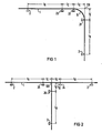
- the device according to the invention is arranged according to FIG. 1 in the area of a pipe bend 11.
- pipe clamps 21 and 22 adjacent to the pipe bend 11 are located at a distance L E from the apex 110 of the pipe bend 11 on the pipe 1.
- the third pipe clamp 23 is arranged on one of the straight legs of the pipe 1 at a distance L E from the adjacent pipe clamp 22 .
- the distance L E within the device according to the invention for mechanical decoupling is one tenth of a mounting distance L R required on the rest of the piping system.
- a commercially available pipe clamp 24 to 26 is arranged at a distance L E from the branch point 120 on each pipeline branch.
- the three pipe clamps 24 to 26 form the corners of a triangle.
- Their distances L E from branch point 120 are one tenth of the bracket distance L R on the piping system.
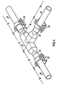
- a device according to the invention for the mechanical decoupling of a pipeline system which is arranged according to FIG. 1 in the area of a pipe bend 11, is shown in perspective in FIG. 3.
- the pipe bend 11 is welded to straight pipe sections 13 and 14 with weld seams 31.
- the commercially available pipe clamps 21 and 22 are attached to the straight pipe sections 13 and 14 on both sides of the pipe bend 11.
- the distance L E according to the invention from the vertex 110 of the pipe bend 11 is sufficiently large so that the weld seams 31 can be examined at any time even with test equipment.
- the third pipe clamp 23, which forms the device according to the invention together with the two other pipe clamps 21 and 22, is arranged on the straight pipe section 14 at a distance L E from the pipe clamp 22.
- the pipe clamp 23 can also be arranged on the straight pipe section 13 at a distance L E from the pipe clamp 21.
- a device according to the invention for the mechanical decoupling of a pipeline system in the region of a pipeline branch is shown in perspective in FIG. 4.
- the branch is realized by a T-piece 12 to which straight pipe sections 15, 16 and 17 are welded.
- the three pipe clamps 24 to 26 arranged on the straight pipe pieces 15, 16 and 17 are arranged from the branch point 120 in the T-piece 12 at the distance L E according to the invention.
- This distance L E according to the invention is so large that the welds 32 between the T-piece 12 and the straight pipe sections 15, 16 and 17 can be checked at any time even with test equipment.
- the pipe clamps 21 to 23, 24 to 26 are arranged according to the invention on the piping system so that they form the corners of a triangle.
- a decoupling device according to the invention is therefore arranged in the region of a pipe bend 11 or a T-piece 12.
- the arrangement of the pipe clamps 21 to 23, 24 to 26 in the form of a triangle and the spatial distances within this arrangement work together in such a way that a mechanical decoupling of the piping system is achieved, which is equivalent to that of a rigid fixed point.
Description
Die Erfindung betrifft eine Einrichtung zur mechanischen Entkopplung eines Rohrleitungssystems, das mindestens ein Verbindungsrohrstück aufweist, mit dem von einem Verbindungspunkt ausgehend verschieden gerichtete gerade Rohrleitungsabschnitte verbunden sind, wobei Rohrleitungen des Rohrleitungssystems in gleichen, von der Belastbarkeit der Rohre abhängenden Abständen in mit einem Gebäude fest verbundenen Halterungen gelagert sind und, damit Schwingungen des Rohrleitungssystems berechenbar sind, durch mindestens eine Festpunkthalterung unbeweglich gehalten sind.The invention relates to a device for the mechanical decoupling of a pipeline system, which has at least one connecting pipe piece, with which straight pipe sections of different directions are connected starting from a connection point, pipelines of the pipeline system being connected to a building at the same distances depending on the load capacity of the pipes Brackets are stored and, so that vibrations of the piping system can be calculated, are held immovably by at least one fixed point bracket.
Rohre eines Rohrleitungssystems werden gemäß "Heating/Piping/Air Conditioning 57 (1985)" mit geeigneten Halterungen an einem Gebäude abgestützt. Dabei ist es besonders wichtig, daß im Bereich eines Rohrbogens Halterungen angebracht sind. Dadurch ist eine stabile Lagerung des gesamten Rohrleitungssystems stets gewährleistet.Pipes in a piping system are supported on a building using suitable brackets in accordance with "Heating / Piping / Air Conditioning 57 (1985)". It is particularly important that brackets are attached in the area of a pipe bend. This ensures that the entire piping system is always stable.
Auf Rohrleitungssysteme wirken verschiedenartige äußere Kräfte ein. Die durch diese Kräfte verursachten Auslenkungen der Rohre sind nur mit sehr großem Aufwand zu erfassen und zu berechnen. Um große Rohrleitungssysteme einer einfachen Berechnung zugänglich zu machen, ist es üblich, daß die Systeme durch geeignete Entkopplungseinrichtungen unterteilt sind.Various external forces act on piping systems. The deflections of the pipes caused by these forces can only be recorded and calculated with great effort. In order to make large piping systems easily accessible, it is common for the systems to be divided by suitable decoupling devices.
Zur mechanischen Entkopplung eines Rohrleitungssystems ist ein Festpunkt erforderlich. Ein Festpunkt ist beispielsweise aus "Dubbei: Taschenbuch für den Maschinenbau, Springer Verlag, 1981" bekannt. Der mechanische Aufbau eines solchen Festpunktes ist dort nicht beschrieben.A fixed point is required for the mechanical decoupling of a pipeline system. A benchmark is known for example from "Dubbei: Taschenbuch für den Maschinenbau, Springer Verlag, 1981". The mechanical structure of such a fixed point is not described there.
Ein geeigneter Festpunkt für ein Rohrleitungssystem ist auch aus "Klinger-Taschenbuch für Heizungs-, Lüftungs- und Badetechniker, Carl Marhold Verlag, 1968" bekannt. Dort wird eine handelsübliche Festpunktschelle erwähnt. Diese Festpunktschelle zeichnet sich durch eine große träge Masse aus.A suitable benchmark for a piping system is also known from "Klinger paperback for heating, ventilation and bathing technicians, Carl Marhold Verlag, 1968". A commercially available benchmark is mentioned there. This fixed point clamp is characterized by a large, inert mass.
Eine bekannte Einrichtung zur mechanischen Entkopplung eines Rohrleitungssystems besteht folglich aus einem aufwendigen, schweren Festpunktformstück, z.B. aus Stahl, das in der Stahlbetonkonstruktion eines Gebäudes verankert ist und ein Rohr des Rohrleitungssystems über eine bestimmte Länge umfaßt. Durch ein solches Festpunktformstück wird gewährleistet, daß selbst durch die größten möglichen äußeren Kräfte die Rohrleitung am Festpunkt nicht ausgelenkt wird.A known device for the mechanical decoupling of a pipeline system consequently consists of a complex, heavy fixed point fitting, e.g. made of steel, which is anchored in the reinforced concrete structure of a building and comprises a pipe of the piping system over a certain length. Such a fixed point fitting ensures that the pipeline at the fixed point is not deflected even by the greatest possible external forces.
An großen Rohrleitungssystemen treten große Kräfte auf, die ein sehr stabiles und damit schweres Festpunktformstück erfordern. Ein derartiges Festpunktformstück erfordert einen großen Fertigungsaufwand, da neben dem hohen Materialbedarf jedes Formstück einzeln zu fertigen ist. Außerdem ist wegen des hohen Gewichtes des Formstückes ein großer Aufwand bei der Montage erforderlich. Dazu ist stets ein Hebekran notwendig. Darüber hinaus sind derartige schwere Formstücke nur mit großem konstruktivem Aufwand an der Stahlbetonkonstruktion eines Gebäudes zu befestigen.Large forces occur on large piping systems, which require a very stable and therefore heavy fixed point fitting. Such a fixed point fitting requires a large amount of production work, since in addition to the high material requirement, each fitting has to be manufactured individually. In addition, because of the high weight of the fitting, a great deal of effort is required during assembly. A lifting crane is always necessary for this. In addition, such heavy fittings can only be attached to the reinforced concrete structure of a building with great design effort.
Der Erfindung liegt die Aufgabe zugrunde, eine Einrichtung zur mechanischen Entkopplung eines Rohrleitungssystems zu entwickeln, die mit einfachen und leichten Halterungen für die Rohrleitungen auskommt und trotzdem einen für die Berechnung des Rohrleitungssystems notwendigen Festpunkt sicherstellt. Der Arbeits- und Materialaufwand soll gegenüber dem Einsatz von Festpunktformstücken deutlich verringert werden.The invention has for its object to develop a device for the mechanical decoupling of a piping system, which manages with simple and lightweight brackets for the piping and still ensures a fixed point necessary for the calculation of the piping system. The work and material costs should be significantly reduced compared to the use of fixed point fittings.
Die Aufgabe wird erfindungsgemäß dadurch gelöst, daß die Halterungen ausnahmslos handelsübliche Rohrschellen sind, daß als Festpunkthalterung des Rohrleitungssystems drei Rohrschellen im Bereich eines Verbindungsrohrstückes angeordnet sind, wobei an jedem der verschieden gerichteten Rohrleitungsabschnitte mindestens eine Rohrschelle angeordnet ist, so daß die drei Rohrschellen die Ecken eines Dreieckes bilden, und daß die Abstände zwischen dem Verbindungspunkt der verschieden gerichteten Rohrieitungsabschnitte und den benachbarten, die Festpunkthalterung bildenden Rohrschellen sowie zwischen zwei unmittelbar benachbarten die Festpunkthalterung bildenden Rohrschellen zwischen 9 und 11 Hundertstel des Abstandes zwischen benachbarten, ausschließlich zur Lagerung dienenden übrigen Halterungen des Rohrleitungssystems betragen.The object is achieved in that the brackets are, without exception, commercially available pipe clamps, that three pipe clamps are arranged in the region of a connecting pipe piece as a fixed point holder of the piping system, with at least one pipe clamp being arranged on each of the differently directed pipe sections, so that the three pipe clamps form the corners of one Form a triangle, and that the distances between the connection point of the differently directed pipeline sections and the adjacent pipe clamps forming the fixed point bracket and between two immediately adjacent pipe clamps forming the fixed point bracket are between 9 and 11 hundredths of the distance between adjacent other brackets of the piping system which are used exclusively for storage .
Eine derartige Einrichtung zur mechanischen Entkopplung eines Rohrleitungssystems wirkt wie ein Hochpaßfilter zwischen den Teilen des Systems. Obwohl jede einzelne handelsübliche Rohrschelle nicht in der Lage ist, mögliche Schwingungen des Rohres zu unterbinden, wird durch die Kombination von drei solchen Rohrschellen, die mit kurzen Abständen nach Art eines Dreieckes angeordnet sind, ein für die Berechnung notwendiger Festpunkt des Rohrleitungssystems sichergestellt.Such a device for the mechanical decoupling of a pipeline system acts like a high-pass filter between the parts of the system. Although each individual commercially available pipe clamp is not able to prevent possible vibrations of the pipe, the combination of three such pipe clamps, which are arranged at short intervals in the manner of a triangle, ensures a fixed point of the piping system necessary for the calculation.
Hiermit wird der Vorteil erzielt, daß der Festpunkt zur mechanischen Entkopplung eines Rohrleitungssystems mit handelsüblichen Rohrschellen auf wirtschaftliche Weise zu erstellen ist. Darüber hinaus sind diese Rohrschellen erheblich leichter als bekannte Festpunktformstücke und sind daher leichter handhabbar.This has the advantage that the fixed point for the mechanical decoupling of a piping system with commercially available pipe clamps can be created in an economical manner. In addition, these pipe clamps are considerably lighter than known fixed point fittings and are therefore easier to handle.
Ein Verbindungsrohrstück in einem Rohrleitungssystem ist beispielsweise ein Rohrbogen, der mit zwei geraden Rohrleitungsabschnitten verbunden ist. Der Verbindungspunkt ist hierbei der Scheitelpunkt des Rohrbogens, der definitionsgemäß derjenige Punkt ist, in dem sich die gedachten Verlängerungen der geraden Rohrleitungsabschnitte schneiden. Im Bereich des Rohrbogens wird ein Festpunkt durch zwei vor dem Rohrbogen und eine hinter dem Rohrbogen an den geraden Rohrleitungsabschnitten angeordnete Rohrschellen gebildet. Ein gleichwertiger Festpunkt wird gebildet, falls eine Rohrschelle vor und zwei hinter dem Rohrbogen positioniert sind. Die Abstände zwischen dem Scheitelpunkt des Rohrbogens und den beiden dem Rohrbogen benachbarten Rohrschellen des Festpunktes betragen jeweils zwischen 9 und 11 Hundertstel des Abstandes zwischen benachbarten Halterungen, die ausschließlich zur Lagerung dienen. Den gleichen kurzen Abstand haben die beiden am geraden Rohrleitungsabschnitt unmittelbar benachbarten Rohrschellen des Festpunktes.A connecting pipe piece in a pipe system is, for example, a pipe bend which is connected to two straight pipe sections. The connection point is the vertex of the pipe bend, which by definition is the point at which the imaginary extensions of the straight pipe sections intersect. In the area of the pipe bend, a fixed point is formed by two pipe clamps arranged in front of the pipe bend and one behind the pipe bend on the straight pipe sections. An equivalent fixed point is formed if one pipe clamp is positioned in front of and two behind the pipe bend. The distances between the apex of the pipe bend and the two pipe clamps adjacent to the pipe bend of the fixed point are between 9 and 11 hundredths of the distance between adjacent brackets, which are used exclusively for storage. The the two pipe clamps of the fixed point immediately adjacent to the straight pipe section have the same short distance.
In jedem Rohrleitungssystem sind viele Rohrbögen vorhanden. Überall dort ist eine erfindungsgemäße Einrichtung zur mechanischen Entkopplung des Rohrleitungssystems anbringbar.There are many pipe bends in every pipe system. A device according to the invention for mechanical decoupling of the piping system can be attached anywhere.
Nach einem anderen Beispiel ist ein geeignetes Verbindungsrohrstück zum Anordnen eines Festpunktes ein T-Stück, mit dem drei gerade Rohrleitungsabschnitte verbunden sind. Hierbei ist als Verbindungspunkt der Abzweigepunkt des T-Stückes anzusehen. Der Festpunkt wird durch jeweils eine Rohrschelle in jedem an das T-Stück angrenzenden Rohrleitungsabschnitt gebildet. Dabei betragen die Abstände zwischen dem Abzweigepunkt des T-Stückes und den drei benachbarten Rohrschellen jeweils zwischen 9 und 11 Hundertstel des Abstandes zwischen benachbarten Hälterungen des Rohrleitungssystems, die ausschließlich zur Lagerung dienen.According to another example, a suitable connecting pipe piece for arranging a fixed point is a T-piece, with which three straight pipe sections are connected. The junction point of the T-piece is to be regarded as the connection point. The fixed point is formed by a pipe clamp in each pipe section adjacent to the T-piece. The distances between the branch point of the T-piece and the three adjacent pipe clamps are each between 9 and 11 hundredths of the distance between adjacent holders of the piping system, which are used exclusively for storage.
In einem großen Rohrleitungssystem sind mehrere Abzweigungen vorhanden. Daher sind zusätzlich zu den Positionen im Bereich der Rohrbögen noch viele andere Orte zum Aufbau der erfindungsgemäßen Einrichtung zur mechanischen Entkopplung des Rohrleitungssystems vorhanden. Im übrigen reicht in den meisten Fällen für die notwendige Berechnung des Rohrleitungssystems eine einzige Einrichtung zur mechanischen Entkopplung aus.There are multiple branches in a large piping system. Therefore, in addition to the positions in the area of the pipe bends, there are many other places for the construction of the device according to the invention for the mechanical decoupling of the pipe system. In most cases, a single device for mechanical decoupling is sufficient for the necessary calculation of the piping system.
Jedes Rohrleitungssystem enthält Rohrbögen und in der Regel auch T-Stücke. Die erfindungsgemäße Einrichtung zur mechanischen Entkopplung des Rohrleitungssystems ist folglich an jedem Rohrleitungssystem einsetzbar.Every pipe system contains pipe bends and usually also T-pieces. The device according to the invention for mechanical decoupling of the piping system can consequently be used on any piping system.
Damit die drei, die Ecken eines Dreiecks bildenden Rohrschellen derart zusammenwirken, daß ein Festpunkt gebildet wird, sind die Abstände zwischen dem Verbindungspunkt der verschieden gerichteten Rohrleitungsabschnitte und den benachbarten Rohrschellen ebenso wie der Abstand zwischen zwei an einem Rohrleitungsabschnitt unmittelbar benachbarten Festpunktrohrschellen wesentlich kürzer als die Abstände der übrigen Halterungen. Ein für die Berechnung des Rohrleitungssystems stabiler Festpunkt ist gewährleistet, falls die Abstände innerhalb der erfindungsgemäßen Einrichtung zwischen 9 und 11 Hundertstel eines Abstandes zwischen den übrigen ausschließlich zur Lagerung dienenden und in gleichen Abständen angeordneten Halterungen des Rohrleitungssystems betragen.So that the three pipe clamps forming the corners of a triangle work together in such a way that a fixed point is formed, the distances between the connection point of the differently directed pipe sections and the adjacent pipe clips as well as the distance between two fixed point pipe clips directly adjacent to a pipe section are significantly shorter than the distances the other brackets. A stable fixed point for the calculation of the pipeline system is ensured if the distances within the device according to the invention are between 9 and 11 hundredths of a distance between the other supports of the pipeline system which are used exclusively for storage and are arranged at equal intervals.
Die regelmäßigen Abstände zwischen den Halterungen des Rohrleitungssystems sind vorgegeben und hängen vom Material, der Wandstärke und dem Durchmesser der Rohre ab. Die Abstände innerhalb der erfindungsgemäßen Entkopplungseinrichtung stehen in dem erfindungsgemäßen Verhältnis zu den regelmäßigen Abständen. Dadurch wird der Vorteil erzielt, daß ein stabiler Festpunkt am Rohrleitungssystem mit einfachen handelsüblichen Rohrschellen zu bauen ist, die leicht handhabbar und zu montieren sind. Die nach der Erfindung vorgesehenen Abstände innerhalb der erfindungsgemäßen Entkoppelungseinrichtung sind so groß, daß die Schweißnähte am Rohrbogen und am T-Stück jederzeit selbst für Schweißnahtprüfgeräte zugänglich sind.The regular distances between the brackets of the pipe system are specified and depend on the material, the wall thickness and the diameter of the pipes. The distances within the decoupling device according to the invention are in the relationship according to the invention to the regular intervals. This has the advantage that a stable fixed point on the piping system can be built with simple commercially available pipe clamps that are easy to handle and assemble. The distances provided according to the invention within the decoupling device according to the invention are so large that the weld seams on the pipe bend and on the T-piece are accessible at any time even for weld seam testing devices.
Mit der Erfindung wird der Vorteil erzielt, daß ein zur Berechnung des Rohrleitungssystems notwendiger Festpunkt am System mit einfachen Mitteln leicht aufzubauen ist.The advantage of the invention is that a fixed point on the system which is necessary for the calculation of the piping system can be easily set up with simple means.
Die Erfindung wird anhand der Zeichnung näher erläutert:
- Fig. 1 zeigt im Bereich eines Rohrbogens die erfindungsgemäße Einrichtung zur mechanischen Entkopplung eines Rohrleitungssystems in verzerrtem Maßstab.
- Fig. 2 zeigt in verzerrtem Maßstab die erfindungsgemäße Einrichtung zur Entkopplung eines Rohrleitungssystems im Bereich eines T-Stückes, das eine Verzweigung der Rohrleitungen bildet.
- Fig. 3 zeigt nicht maßstabsgerecht die Anordnung nach Fig.1 in perspektivischer Darstellung.
- Fig. 4 zeigt nicht maßstabsgerecht die Anordnung nach Fig. 2 in perspektivischer Darstellung.
- 1 shows in the area of a pipe bend the device according to the invention for the mechanical decoupling of a pipe system on a distorted scale.
- 2 shows, on a distorted scale, the device according to the invention for decoupling a pipeline system in the region of a T-piece, which forms a branching of the pipelines.
- FIG. 3 does not show the arrangement according to FIG. 1 in a perspective representation to scale.
- FIG. 4 does not show the arrangement according to FIG. 2 in a perspective representation to scale.
Rohrleitungen 1 eines Rohrleitungssystems sind durch Halterungen 2 mit einem Gebäude fest verbunden. Der Halterungsabstand LR ist durch mechanische Eigenschaften der Rohre festgelegt. An gleichartigen Rohren ist der Halterungsabstand LR konstant. Damit auch große Rohrleitungssysteme einer Berechnung zugänglich sind, sind diese Systeme durch geeignete Entkopplungseinrichtungen unterteilt. Die erfindungsgemäße Einrichtung zur mechanischen Entkopplung besteht aus drei handelsüblichen Rohrschellen 21 bis 23 oder 24 bis 26, die auf im Vergleich zum Halterungsabstand LR kleinem Raum so angeordnet sind, daß sie die Ecken eines Dreieckes bilden.Pipes 1 of a pipe system are firmly connected to a building by brackets 2. The bracket distance L R is determined by the mechanical properties of the pipes. The bracket distance L R is constant on pipes of the same type. These systems are subdivided by suitable decoupling devices so that large piping systems can be accessed for calculation. The device according to the invention for mechanical decoupling consists of three commercially
Die erfindungsgemäße Einrichtung ist nach Fig. 1 im Bereich eines Rohrbogens 11 angeordnet. Dabei befinden sich dem Rohrbogen 11 benachbarte Rohrschellen 21 und 22 in Abständen LE vom Scheitelpunkt 110 des Rohrbogens 11 entfernt an der Rohrleitung 1. Die dritte Rohrschelle 23 ist an einem der geraden Schenkel der Rohrleitung 1 im Abstand LE von der benachbarten Rohrschelle 22 angeordnet. Der Abstand LE innerhalb der erfindungsgemäßen Einrichtung zur mechanischen Entkopplung beträgt ein Zehntel eines am übrigen Rohrleitungssystem notwendigen Halterungsabstandes LR.The device according to the invention is arranged according to FIG. 1 in the area of a pipe bend 11. In this case, pipe clamps 21 and 22 adjacent to the pipe bend 11 are located at a distance L E from the apex 110 of the pipe bend 11 on the pipe 1. The
Zur Entkopplung eines Rohrleitungssystems im Bereich eines T-Stückes 12, das eine Abzweigung nach Fig. 2 bildet, sind im Abstand LE vom Abzweigepunkt 120 an jedem Rohrleitungszweig jeweils eine handelsübliche Rohrschelle 24 bis 26 angeordnet. Die drei Rohrschellen 24 bis 26 bilden die Ecken eines Dreieckes. Ihre Abstände LE vom Abzweigepunkt 120 betragen ein Zehntel des Halterungsabstandes LR am Rohrleitungssystem.To decouple a pipeline system in the area of a T-
An den Ecken eines Dreieckes mit erfindungsgemäßen Abständen angeordnete einfache, handelsübliche Rohrschellen 21 bis 23 oder 24 bis 26, wirken so zusammen, daß sie einen Festpunkt bilden, der das Rohrleitungssystem mechanisch entkoppelt. Durch einen solchen erfindungsgemäßen Festpunkt wird das Rohrleitungssystem einfach und kostengünstig der Berechnung zugänglich gemacht.At the corners of a triangle with spacings according to the invention, simple, commercially available pipe clamps 21 to 23 or 24 to 26 work together in such a way that they form a fixed point which mechanically decouples the piping system. Through such a festival according to the invention the piping system is made accessible to the calculation simply and inexpensively.
Eine erfindungsgemäße Einrichtung zur mechanischen Entkopplung eines Rohrleitungssystems, die gemäß Fig: 1 im Bereich eines Rohrbogens 11 angeordnet ist, zeigt Fig. 3 in perspektivischer Darstellung. Der Rohrbogen 11 ist mit Schweißnähten 31 an gerade Rohrstücke 13 und 14 angeschweißt. Die handelsüblichen Rohrschellen 21 und 22 sind auf beiden Seiten des Rohrbogens 11 an den geraden Rohrstücken 13 und 14 angebracht. Dabei ist der erfindungsgemäße Abstand LE vom Scheitelpunkt 110 des Rohrbogens 11 ausreichend groß, so daß die Schweißnähte 31 jederzeit selbst mit Prüfgeräten zu untersuchen sind. Die dritte Rohrschelle 23, die gemeinsam mit den beiden anderen Rohrschellen 21 und 22 die erfindungsgemäße Einrichtung bildet, ist am geraden Rohrstück 14 im Abstand LE von der Rohrschelle 22 angeordnet. Die Rohrschelle 23 kann ebenso am geraden Rohrstück 13 im Abstand LE von der Rohrschelle 21 angeordnet sein.A device according to the invention for the mechanical decoupling of a pipeline system, which is arranged according to FIG. 1 in the area of a pipe bend 11, is shown in perspective in FIG. 3. The pipe bend 11 is welded to
Eine erfindungsgemäße Einrichtung zur mechanischen Entkopplung eines Rohrleitungssystems im Bereich einer Rohrleitungsabzweigung ist in Fig. 4 perspektivisch dargestellt. Dort ist die Abzweigung durch ein T-Stück 12 realisiert, an das gerade Rohrstücke 15,16 und 17 angeschweißt sind. Die drei an den geraden Rohrstücken 15, 16 und 17 angeordneten Rohrschellen 24 bis 26 sind vom Abzweigepunkt 120 im T-Stück 12 im erfindungsgemäßen Abstand LE angeordnet. Dieser erfindungsgemäße Abstand LE ist so groß, daß eine Überprüfung der Schweißnähte 32 zwischen dem T-Stück 12 und den geraden Rohrstücken 15, 16 und 17 jederzeit selbst mit Prüfgeräten durchführbar ist.A device according to the invention for the mechanical decoupling of a pipeline system in the region of a pipeline branch is shown in perspective in FIG. 4. There the branch is realized by a T-
Die Rohrschellen 21 bis 23, 24 bis 26 sind erfindingsgemäß am Rohrleitungssystem so angeordnet, daß sie die Ecken eines Dreieckes bilden. Daher ist eine erfindungsgemäße Entkopplungseinrichtung im Bereich eines Rohrbogens 11 oder eines T-Stückes 12 angeordnet. Die Anordnung der Rohrschellen 21 bis 23, 24 bis 26 in Form eines Dreieckes und die räumlichen Abstände innerhalb dieser Anordnung wirken derart zusammen, daß eine mechanische Entkopplung des Rohrleitungssystems erzielt wird, die derjenigen eines steifen Festpunktes gleichwertig ist.The pipe clamps 21 to 23, 24 to 26 are arranged according to the invention on the piping system so that they form the corners of a triangle. A decoupling device according to the invention is therefore arranged in the region of a pipe bend 11 or a T-
Claims (3)
Applications Claiming Priority (2)
| Application Number | Priority Date | Filing Date | Title |
|---|---|---|---|
| DE3610331 | 1986-03-26 | ||
| DE3610331 | 1986-03-26 |
Publications (2)
| Publication Number | Publication Date |
|---|---|
| EP0242584A1 EP0242584A1 (en) | 1987-10-28 |
| EP0242584B1 true EP0242584B1 (en) | 1990-12-05 |
Family
ID=6297376
Family Applications (1)
| Application Number | Title | Priority Date | Filing Date |
|---|---|---|---|
| EP87103788A Expired - Lifetime EP0242584B1 (en) | 1986-03-26 | 1987-03-16 | Device for the mechanical decoupling of a pipeline system |
Country Status (6)
| Country | Link |
|---|---|
| US (1) | US4783030A (en) |
| EP (1) | EP0242584B1 (en) |
| JP (1) | JPS62233586A (en) |
| CA (1) | CA1321185C (en) |
| DE (1) | DE3766531D1 (en) |
| ES (1) | ES2018490B3 (en) |
Families Citing this family (22)
| Publication number | Priority date | Publication date | Assignee | Title |
|---|---|---|---|---|
| DE8806645U1 (en) * | 1988-05-20 | 1989-09-14 | Lisega Kraftwerkstechnik Gmbh, 2730 Zeven, De | |
| US4927201A (en) * | 1988-12-27 | 1990-05-22 | Andrew Froutzis | Means for releasably anchoring vehicle seats |
| EP0427880A1 (en) * | 1989-11-13 | 1991-05-22 | Siemens Aktiengesellschaft | Holding device for pipes and method for manufacturing the same |
| US5393024A (en) * | 1990-09-12 | 1995-02-28 | Daubenspeck; Richard P. | Water heater tank support |
| US5741458A (en) * | 1996-01-19 | 1998-04-21 | Rowley; William | Method of forming a water heater tube |
| US6254051B1 (en) | 1997-01-15 | 2001-07-03 | Securus, Inc. | Restraining system for water heaters |
| US5897086A (en) * | 1997-08-15 | 1999-04-27 | Quick Strap, Inc. | System and method for restraining water heaters from tipping over due to earthquake or severe winds |
| US6254052B1 (en) | 1998-01-14 | 2001-07-03 | Securus, Inc. | Restraining system for water heaters |
| US6095472A (en) * | 1998-01-14 | 2000-08-01 | Securus, Inc. | Restraining system for water heaters |
| US6190261B1 (en) * | 1998-09-15 | 2001-02-20 | Flowserve Management Company | Pump assembly shaft guard |
| US6481803B2 (en) * | 2001-01-16 | 2002-11-19 | Kennametal Inc. | Universal bit holder block connection surface |
| US6527233B2 (en) * | 2001-04-24 | 2003-03-04 | Inertia Dynamics, Inc. | Device for clamping a shaft |
| US20030038217A1 (en) * | 2001-08-22 | 2003-02-27 | Rivers James Michael | Adjustable support strap for pipes and the like |
| US6729588B2 (en) * | 2001-11-16 | 2004-05-04 | Wilkinson, Iii Joseph | Pipe shoe and method |
| US7093727B2 (en) | 2004-09-14 | 2006-08-22 | Musico M James | Plural utensils support system |
| US20060175338A1 (en) * | 2004-12-16 | 2006-08-10 | Pishock Charles T Jr | Tank outlet fitting with flange |
| US7153064B2 (en) * | 2005-02-25 | 2006-12-26 | Playstar, Inc. | Pipe sleeve for a floating dock |
| US7331549B2 (en) * | 2005-06-03 | 2008-02-19 | Woodworker's Supply Inc. | Pipe brackets and pipe hanging system |
| CN102084137B (en) * | 2009-04-23 | 2013-10-16 | 萱场工业株式会社 | Pipe securing structure for cylinder tube |
| JP5445507B2 (en) * | 2010-06-03 | 2014-03-19 | 株式会社デンソー | Power converter |
| CA2942855C (en) * | 2014-03-28 | 2020-04-07 | Public Joint Stock Company "Transneft" | Method for installing a stationary support in a planned position |
| NL2019747B1 (en) * | 2017-10-17 | 2019-04-24 | Walraven Holding Bv J Van | Riser clamp with a vibration isolation element |
Family Cites Families (5)
| Publication number | Priority date | Publication date | Assignee | Title |
|---|---|---|---|---|
| AT221445B (en) * | 1959-10-24 | 1962-05-25 | Voest Ag | Pressure pipeline for hydropower plants |
| US3539137A (en) * | 1968-03-25 | 1970-11-10 | Birma Products Corp | Pipe saddle |
| US3936001A (en) * | 1974-12-09 | 1976-02-03 | Bolton-Emerson, Inc. | Anti-sag device for paper mill showers |
| IT1129382B (en) * | 1980-11-28 | 1986-06-04 | Fist Snc Di Bosso Giacomo | HOSE |
| US4513934A (en) * | 1982-11-03 | 1985-04-30 | Miro Industries, Inc. | Pipe-supporting device |
-
1987
- 1987-03-16 DE DE8787103788T patent/DE3766531D1/en not_active Expired - Fee Related
- 1987-03-16 ES ES87103788T patent/ES2018490B3/en not_active Expired - Lifetime
- 1987-03-16 EP EP87103788A patent/EP0242584B1/en not_active Expired - Lifetime
- 1987-03-20 JP JP62067701A patent/JPS62233586A/en active Pending
- 1987-03-24 CA CA000532862A patent/CA1321185C/en not_active Expired - Fee Related
- 1987-03-25 US US07/030,740 patent/US4783030A/en not_active Expired - Fee Related
Non-Patent Citations (2)
| Title |
|---|
| K.W. USEMANN, "Klinger-Taschenbuch für Heizungs,-Lüftungs-und Badetechniker", 1968, Karl Marholdverlagsbuchhandlung, Seite 222 * |
| W. BEITZ und K.H. KUTTNER, "Dubbel", 1981, Springer-Verlag, Berlin - Heidelberg - New York, Seite 498 * |
Also Published As
| Publication number | Publication date |
|---|---|
| DE3766531D1 (en) | 1991-01-17 |
| JPS62233586A (en) | 1987-10-13 |
| US4783030A (en) | 1988-11-08 |
| EP0242584A1 (en) | 1987-10-28 |
| ES2018490B3 (en) | 1991-04-16 |
| CA1321185C (en) | 1993-08-10 |
Similar Documents
| Publication | Publication Date | Title |
|---|---|---|
| EP0242584B1 (en) | Device for the mechanical decoupling of a pipeline system | |
| EP1642075B1 (en) | Exhaust steam line for steam plants | |
| AT408139B (en) | INSTALLATION DEVICE FOR PIPELINES | |
| DE3910757C2 (en) | ||
| EP1388619B1 (en) | Device for fixing a pipe | |
| EP0568887B1 (en) | Mounting bar | |
| EP1764542A1 (en) | Industrial equipment chassis | |
| DE10158054B4 (en) | Ceiling element for the production of a Klimadecke, arrangement for the air conditioning of a room, and method for mounting a Klimadecke | |
| DE2014093C3 (en) | Distribution and collection device for a heating system | |
| DE3935385C2 (en) | Traverse for industrial bracket construction | |
| EP0046519B1 (en) | Supporting mat for heating elements of a floor heating system | |
| DE202005009190U1 (en) | Holding element for holding at least one pipeline of a pipeline heating system | |
| EP0660019B1 (en) | Methode for connecting a plastic pipe fitting with at least two fastening holes to a perforated sheet metal support | |
| DE10114505B4 (en) | Heat generator for heating purposes and water heating | |
| DE3822086C1 (en) | Overground distant pipeline system | |
| CH532726A (en) | Fastening device | |
| EP3757305B1 (en) | Working space | |
| DE4310036A1 (en) | Connection for sheet-like, frame-like, or box-like structures | |
| DE10129666A1 (en) | Heat exchanger ceiling tile has heat exchanger pipes clamped onto the top surface by a clamping profile secured onto threaded fasteners | |
| DE3416512C1 (en) | Device for the retention and mounting of pipelines | |
| DE3007229A1 (en) | CABLE DISTRIBUTOR | |
| EP0364718B1 (en) | Built-in cupboard | |
| DE19632322A1 (en) | Pipe mat installation method | |
| DE4420479A1 (en) | Holding device for heating tubes | |
| EP0679830A2 (en) | Pipe branch element |
Legal Events
| Date | Code | Title | Description |
|---|---|---|---|
| PUAI | Public reference made under article 153(3) epc to a published international application that has entered the european phase |
Free format text: ORIGINAL CODE: 0009012 |
|
| AK | Designated contracting states |
Kind code of ref document: A1 Designated state(s): BE CH DE ES FR GB LI |
|
| 17P | Request for examination filed |
Effective date: 19880125 |
|
| 17Q | First examination report despatched |
Effective date: 19890224 |
|
| GRAA | (expected) grant |
Free format text: ORIGINAL CODE: 0009210 |
|
| AK | Designated contracting states |
Kind code of ref document: B1 Designated state(s): BE CH DE ES FR GB LI |
|
| REF | Corresponds to: |
Ref document number: 3766531 Country of ref document: DE Date of ref document: 19910117 |
|
| GBT | Gb: translation of ep patent filed (gb section 77(6)(a)/1977) | ||
| ET | Fr: translation filed | ||
| PLBE | No opposition filed within time limit |
Free format text: ORIGINAL CODE: 0009261 |
|
| STAA | Information on the status of an ep patent application or granted ep patent |
Free format text: STATUS: NO OPPOSITION FILED WITHIN TIME LIMIT |
|
| 26N | No opposition filed | ||
| PGFP | Annual fee paid to national office [announced via postgrant information from national office to epo] |
Ref country code: GB Payment date: 19940218 Year of fee payment: 8 |
|
| PGFP | Annual fee paid to national office [announced via postgrant information from national office to epo] |
Ref country code: BE Payment date: 19940308 Year of fee payment: 8 |
|
| PG25 | Lapsed in a contracting state [announced via postgrant information from national office to epo] |
Ref country code: GB Effective date: 19950316 |
|
| PGFP | Annual fee paid to national office [announced via postgrant information from national office to epo] |
Ref country code: FR Payment date: 19950323 Year of fee payment: 9 |
|
| PG25 | Lapsed in a contracting state [announced via postgrant information from national office to epo] |
Ref country code: BE Effective date: 19950331 |
|
| PGFP | Annual fee paid to national office [announced via postgrant information from national office to epo] |
Ref country code: DE Payment date: 19950518 Year of fee payment: 9 |
|
| PGFP | Annual fee paid to national office [announced via postgrant information from national office to epo] |
Ref country code: CH Payment date: 19950614 Year of fee payment: 9 |
|
| BERE | Be: lapsed |
Owner name: SIEMENS A.G. Effective date: 19950331 |
|
| GBPC | Gb: european patent ceased through non-payment of renewal fee |
Effective date: 19950316 |
|
| PGFP | Annual fee paid to national office [announced via postgrant information from national office to epo] |
Ref country code: ES Payment date: 19960311 Year of fee payment: 10 |
|
| PG25 | Lapsed in a contracting state [announced via postgrant information from national office to epo] |
Ref country code: LI Effective date: 19960331 Ref country code: CH Effective date: 19960331 |
|
| REG | Reference to a national code |
Ref country code: CH Ref legal event code: PL |
|
| PG25 | Lapsed in a contracting state [announced via postgrant information from national office to epo] |
Ref country code: FR Effective date: 19961129 |
|
| PG25 | Lapsed in a contracting state [announced via postgrant information from national office to epo] |
Ref country code: DE Effective date: 19961203 |
|
| REG | Reference to a national code |
Ref country code: FR Ref legal event code: ST |
|
| PG25 | Lapsed in a contracting state [announced via postgrant information from national office to epo] |
Ref country code: ES Free format text: LAPSE BECAUSE OF NON-PAYMENT OF DUE FEES Effective date: 19970317 |
|
| REG | Reference to a national code |
Ref country code: ES Ref legal event code: FD2A Effective date: 19990201 |